Page 1076 of 3000
2GR-FE ENGINE MECHANICAL – ENGINE UNITEM–129
EM
(b) Using a piston ring expander, install the
compression ring as shown in the illustration.
(c) Position the piston rings so that the ring ends are as
shown in the illustration.
NOTICE:
Do not align the ring ends.
6. INSTALL CRANKSHAFT BEARING
(a) Clean the main journal and both surfaces of the
bearing.
NOTICE:
Main bearings come in widths between 18.0 mm
(0.709 in.) and 21.0 mm (0.827 in.). Install the
21.0 mm (0.827 in.) bearings in the No. 1 and No.
4 cylinder block journal positions with the main
bearing cap. Install the 18.0 mm (0.709 in.)
bearings in the No. 2 and No. 3 positions.
A131880E03
A131881E01
A124282E02
Page 1087 of 3000

EM–1402GR-FE ENGINE MECHANICAL – ENGINE UNIT
EM
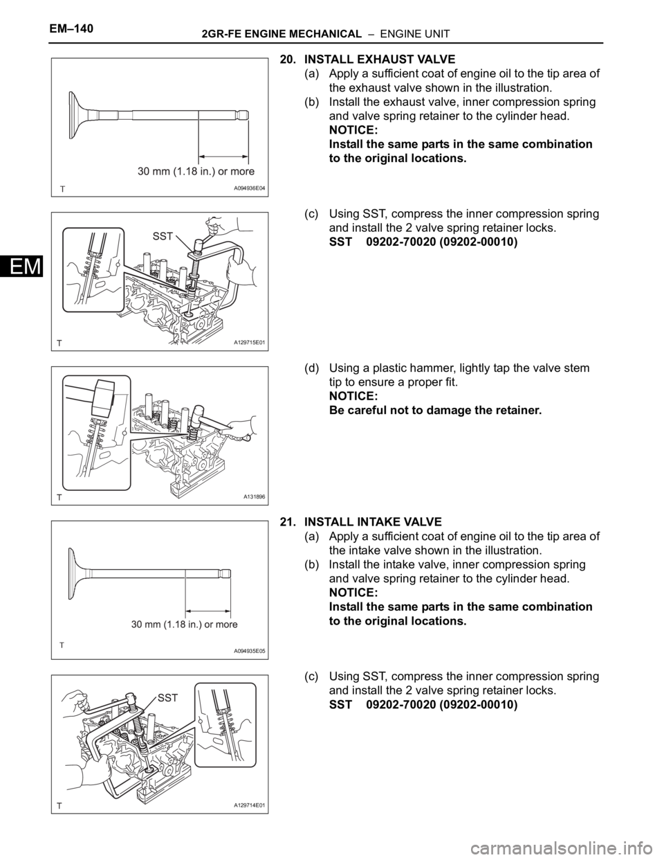
20. INSTALL EXHAUST VALVE
(a) Apply a sufficient coat of engine oil to the tip area of
the exhaust valve shown in the illustration.
(b) Install the exhaust valve, inner compression spring
and valve spring retainer to the cylinder head.
NOTICE:
Install the same parts in the same combination
to the original locations.
(c) Using SST, compress the inner compression spring
and install the 2 valve spring retainer locks.
SST 09202-70020 (09202-00010)
(d) Using a plastic hammer, lightly tap the valve stem
tip to ensure a proper fit.
NOTICE:
Be careful not to damage the retainer.
21. INSTALL INTAKE VALVE
(a) Apply a sufficient coat of engine oil to the tip area of
the intake valve shown in the illustration.
(b) Install the intake valve, inner compression spring
and valve spring retainer to the cylinder head.
NOTICE:
Install the same parts in the same combination
to the original locations.
(c) Using SST, compress the inner compression spring
and install the 2 valve spring retainer locks.
SST 09202-70020 (09202-00010)
A094936E04
A129715E01
A131896
A094935E05
A129714E01
Page 1178 of 3000
EC–222GR-FE EMISSION CONTROL – AIR FUEL RATIO SENSOR (for 2WD)
EC
4. INSTALL FRONT EXHAUST PIPE ASSEMBLY
(a) Check compression springs.
(1) Check the compression springs using vernier
calipers.
Specified length:
38.86 mm (1.5299 in.)
HINT:
If the result is not as specified, replace the
compression spring.
(b) Install the gasket.
(1) Install a new gasket by hand onto the front
exhaust pipe assembly.
(2) Using a plastic hammer and wooden block, tap
in the new gasket until its surface is flush with
the front exhaust pipe.
NOTICE:
• Be careful with the installation direction
of the gasket.
• Do not damage the gasket.
• Do not reuse the gasket.
• To ensure a proper seal, do not use the
exhaust pipe to force the gasket on to the
front exhaust pipe.
(c) Install 2 new gaskets to the front exhaust pipe
assembly.
(d) Install the front exhaust pipe assembly with the 4
nuts.
Torque: 62 N*m (632 kgf*cm, 46 ft.*lbf)
A077857
A076194E04
A162908
Page 1179 of 3000
2GR-FE EMISSION CONTROL – AIR FUEL RATIO SENSOR (for 2WD)EC–23
EC
(e) Install the center exhaust pipe assembly with the 2
compression springs and 2 bolts.
Torque: 43 N*m (438 kgf*cm, 32 ft.*lbf)
(f) Install the No. 1 exhaust pipe support bracket with
the 2 new nuts.
Torque: 21 N*m (214 kgf*cm, 15 ft.*lbf)
(g) Connect the heated oxygen sensor (for Bank 1
sensor 2) connector.
5. CONNECT CABLE TO NEGATIVE BATTERY
TERMINAL
6. INSPECT FOR EXHAUST GAS LEAK
A162949
A165516
Page 1184 of 3000

2GR-FE EMISSION CONTROL – AIR FUEL RATIO SENSOR (for 4WD)EC–29
EC
HINT:
• Use a torque wrench with a fulcrum length of 30
cm (11.81 in.).
• Make sure that SST and wrench are connected
in a straight line.
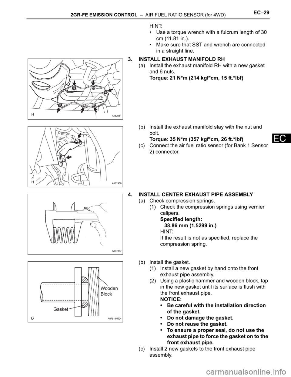
3. INSTALL EXHAUST MANIFOLD RH
(a) Install the exhaust manifold RH with a new gasket
and 6 nuts.
Torque: 21 N*m (214 kgf*cm, 15 ft.*lbf)
(b) Install the exhaust manifold stay with the nut and
bolt.
Torque: 35 N*m (357 kgf*cm, 26 ft.*lbf)
(c) Connect the air fuel ratio sensor (for Bank 1 Sensor
2) connector.
4. INSTALL CENTER EXHAUST PIPE ASSEMBLY
(a) Check compression springs.
(1) Check the compression springs using vernier
calipers.
Specified length:
38.86 mm (1.5299 in.)
HINT:
If the result is not as specified, replace the
compression spring.
(b) Install the gasket.
(1) Install a new gasket by hand onto the front
exhaust pipe assembly.
(2) Using a plastic hammer and wooden block, tap
in the new gasket until its surface is flush with
the front exhaust pipe.
NOTICE:
• Be careful with the installation direction
of the gasket.
• Do not damage the gasket.
• Do not reuse the gasket.
• To ensure a proper seal, do not use the
exhaust pipe to force the gasket on to the
front exhaust pipe.
(c) Install 2 new gaskets to the front exhaust pipe
assembly.
A162951
A162950
A077857
A076194E04
Page 1185 of 3000
EC–302GR-FE EMISSION CONTROL – AIR FUEL RATIO SENSOR (for 4WD)
EC
(d) Install the front exhaust pipe assembly with the 2
nuts and 2 bolts.
Torque: Bolt
43 N*m (440 kgf*cm, 32 ft.*lbf)
Nut
62 N*m (632 kgf*cm, 46 ft.*lbf)
(e) Install the center exhaust pipe assembly with the 2
compression springs and 2 bolts.
Torque: 43 N*m (438 kgf*cm, 32 ft.*lbf)
(f) Attach the clip.
(g) Connect the heated oxygen sensor (for Bank 1
Sensor 2) connector.
5. CONNECT CABLE TO NEGATIVE BATTERY
TERMINAL
6. INSPECT FOR EXHAUST GAS LEAK
A163387
A162949
A163447
Page 1193 of 3000
2GR-FE EMISSION CONTROL – AIR FUEL RATIO SENSOR (for 2WD)EC–19
EC
REMOVAL
1. DISCONNECT CABLE FROM NEGATIVE BATTERY
TERMINAL
2. REMOVE AIR FUEL RATIO SENSOR (for Bank 2
Sensor 1)
(a) Disconnect the sensor connector.
(b) Using SST, remove the sensor from the exhaust
manifold.
SST 09224-00010
3. REMOVE FRONT EXHAUST PIPE ASSEMBLY
(a) Disconnect the heated oxygen sensor (for Bank 1
Sensor 2) connector under the center console.
(b) Remove the 2 bolts and 2 compression springs.
(c) Remove the 6 nuts and front exhaust pipe
assembly.
A162948E01
A162949
A162483
Page 1197 of 3000
EC–262GR-FE EMISSION CONTROL – AIR FUEL RATIO SENSOR (for 4WD)
EC
REMOVAL
1. DISCONNECT CABLE FROM NEGATIVE BATTERY
TERMINAL
CAUTION:
Wait at least 90 seconds after disconnecting the
cable from the negative (-) battery terminal to
prevent airbag and seat belt pretensioner activation.
2. REMOVE AIR FUEL RATIO SENSOR (for Bank 2
Sensor 1)
(a) Disconnect the sensor connector.
(b) Using SST, remove the sensor from the exhaust
manifold.
SST 09224-00010
3. REMOVE CENTER EXHAUST PIPE ASSEMBLY
(a) Disconnect the heated oxygen sensor (for Bank 1
Sensor 2) connector under the center console.
(b) Remove the clip as shown in the illustration.
(c) Remove the 2 bolts and 2 compression springs.
A162948E01
A163447
A162949