2007 NISSAN TIIDA ABS
[x] Cancel search: ABSPage 4582 of 5883

RSU-10
< ON-VEHICLE REPAIR >
COIL SPRING
COIL SPRING
Removal and InstallationINFOID:0000000001724579
REMOVAL
1. Remove rear tires from vehicle using power tool.
2. Remove wheel sensor from wheel hub and bearing assembly. Refer to BRC-83, "
Removal and Installa-
tion" .
CAUTION:
Do not pull on wheel sensor harness.
3. Separate brake tube from wheel cylinder. Refer to BR-15, "
Rear Brake Tube and Hose" .
4. Set jack under rear suspension beam.
5. Remove shock absorber lower side bolt. Refer to RSU-8,
"Removal and Installation" .
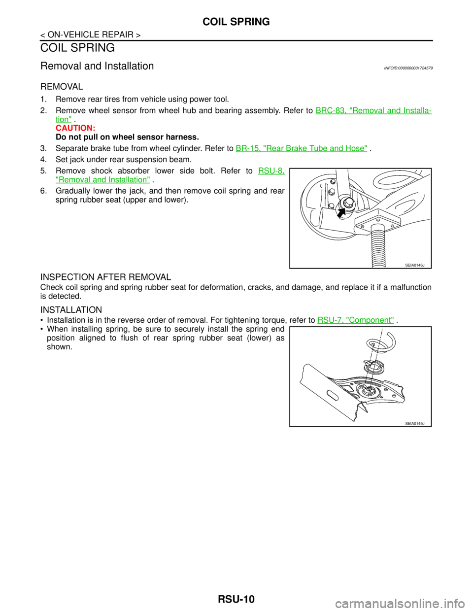
6. Gradually lower the jack, and then remove coil spring and rear
spring rubber seat (upper and lower).
INSPECTION AFTER REMOVAL
Check coil spring and spring rubber seat for deformation, cracks, and damage, and replace it if a malfunction
is detected.
INSTALLATION
Installation is in the reverse order of removal. For tightening torque, refer to RSU-7, "Component" .
When installing spring, be sure to securely install the spring end
position aligned to flush of rear spring rubber seat (lower) as
shown.
SEIA0146J
SEIA0149J
Page 4638 of 5883
![NISSAN TIIDA 2007 Service Repair Manual NATS (NISSAN ANTI-THEFT SYSTEM)
SEC-13
< FUNCTION DIAGNOSIS >[WITH INTELLIGENT KEY SYSTEM]
C
D
E
F
G
H
I
J
L
MA
B
SEC
N
O
P
- Mechanical key
- ABS actuator control unit
- EPS control unit
- IPDM E/R
NISSAN TIIDA 2007 Service Repair Manual NATS (NISSAN ANTI-THEFT SYSTEM)
SEC-13
< FUNCTION DIAGNOSIS >[WITH INTELLIGENT KEY SYSTEM]
C
D
E
F
G
H
I
J
L
MA
B
SEC
N
O
P
- Mechanical key
- ABS actuator control unit
- EPS control unit
- IPDM E/R
](/manual-img/5/57395/w960_57395-4637.png)
NATS (NISSAN ANTI-THEFT SYSTEM)
SEC-13
< FUNCTION DIAGNOSIS >[WITH INTELLIGENT KEY SYSTEM]
C
D
E
F
G
H
I
J
L
MA
B
SEC
N
O
P
- Mechanical key
- ABS actuator control unit
- EPS control unit
- IPDM E/R
NATS trouble diagnosis, system initialization and additional registration of other mechanical key IDs must be
carried out using CONSULT-III hardware and SECURITY CARD.
When NATS initialization has been completed, the ID of the inserted mechanical key or mechanical key IDs
can be carried out.
Possible symptom of NATS malfunction is “Engine cannot start”. In C11, the engine can be started with the
Intelligent Key system and NATS. Identify the possible causes according to “Work Flow”, Refer to SEC-4,
"Work Flow".
If ECM other than Genuine NISSAN is installed, the engine cannot be started. For ECM replacement proce-
dure, refer to SEC-7, "
ECM RE-COMMUNICATING FUNCTION : Description".
PRECAUTIONS FOR KEY REGISTRATION
The key registration is a procedure that erases the current NATS ID once, and then re-registers a new ID.
Therefore the registered Intelligent Key is necessary for this procedure. Before starting the registration oper-
ation collect all registered Intelligent Keys from the customer.
The NATS ID registration is the procedure that registers the ID stored into the transponder (integrated in
mechanical key) to BCM.
The Intelligent Key ID registration is the procedure that registers the ID to Intelligent Key unit.
When performing the Intelligent Key system registration only, the engine cannot be started by inserting the
key into the key cylinder. When performing the NATS registration only, the engine cannot be started by using
the mechanical key.
SECURITY INDICATOR
Always flashes with ignition knob released (ignition knob switch: OFF) condition on ignition knob LOCK posi-
tion.
Always flashes with ignition knob released (ignition knob switch: OFF) condition on mechanical key removed
position.
Turns ON steady when the NATS is activated.
MAINTENANCE INFORMATION
CAUTION:
It is necessary to perform NATS ID registration when replacing any of the following part.
If it's not (or fail to do so), the electrical system may not operate properly.
BCM
ECM
Intelligent Key unit
Intelligent Key
IPDM E/R
NATS antenna amp.
Page 4709 of 5883
![NISSAN TIIDA 2007 Service Repair Manual SEC-84
< FUNCTION DIAGNOSIS >[WITHOUT INTELLIGENT KEY SYSTEM]
NATS (NISSAN ANTI-THEFT SYSTEM)
FUNCTION DIAGNOSIS
NATS (NISSAN ANTI-THEFT SYSTEM)
System DiagramINFOID:0000000001404157
System Descriptio NISSAN TIIDA 2007 Service Repair Manual SEC-84
< FUNCTION DIAGNOSIS >[WITHOUT INTELLIGENT KEY SYSTEM]
NATS (NISSAN ANTI-THEFT SYSTEM)
FUNCTION DIAGNOSIS
NATS (NISSAN ANTI-THEFT SYSTEM)
System DiagramINFOID:0000000001404157
System Descriptio](/manual-img/5/57395/w960_57395-4708.png)
SEC-84
< FUNCTION DIAGNOSIS >[WITHOUT INTELLIGENT KEY SYSTEM]
NATS (NISSAN ANTI-THEFT SYSTEM)
FUNCTION DIAGNOSIS
NATS (NISSAN ANTI-THEFT SYSTEM)
System DiagramINFOID:0000000001404157
System DescriptionINFOID:0000000001404158
INPUT/OUTPUT SIGNAL CHART
BCM
SYSTEM DESCRIPTION
NATS (Nissan Anti-Theft System) has the following immobilizer functions:
Engine immobilizer shows high anti-theft performance to prevent engine start by other than the owner.
Only a key with key ID registered in BCM and ECM can start engine, and shows high anti-theft performance
to prevent key from being copied or stolen.
Security indicator always flashes with mechanical key removed condition (key switch: OFF).
Therefore, NATS warns outsiders that the vehicle is equipped with the anti-theft system. Refer to XX-XX,
"*****".
If system detects malfunction, security indicator illuminate when ignition switch is turned to ON position.
If the owner requires, ignition key ID can be registered for up to 5 keys.
During trouble diagnosis or when the following parts have been replaced, and if ignition key is added, regis-
tration* is required.
*1: All keys kept by the owner of the vehicle should be registered with ignition key.
-ECM
-BCM
- Ignition key
- ABS actuator control unit
- EPS sontrol unit
- IPDM E/R
- Combination meter
NATS trouble diagnosis, system initialization and additional registration of other Ignition key IDs must be car-
ried out using CONSULT-III hardware and SECURITY CARD.
When NATS initialization has been completed, the ID of the inserted ignition key or ignition key IDs can be
carried out.
PIIA1121E
Switch/Input signal Input signal to BCM BCM function Actuator/Output signal
NATS antenna amp. Key ID
NATS Security indicator lamp
Starter request
ECM Engine status signal
Page 4723 of 5883
![NISSAN TIIDA 2007 Service Repair Manual SEC-98
< COMPONENT DIAGNOSIS >[WITHOUT INTELLIGENT KEY SYSTEM]
B2196 DONGLE NG
B2196 DONGLE NG
DescriptionINFOID:0000000001404189
BCM performs the ID verification with the slave control units (ECM, AB NISSAN TIIDA 2007 Service Repair Manual SEC-98
< COMPONENT DIAGNOSIS >[WITHOUT INTELLIGENT KEY SYSTEM]
B2196 DONGLE NG
B2196 DONGLE NG
DescriptionINFOID:0000000001404189
BCM performs the ID verification with the slave control units (ECM, AB](/manual-img/5/57395/w960_57395-4722.png)
SEC-98
< COMPONENT DIAGNOSIS >[WITHOUT INTELLIGENT KEY SYSTEM]
B2196 DONGLE NG
B2196 DONGLE NG
DescriptionINFOID:0000000001404189
BCM performs the ID verification with the slave control units (ECM, ABS actuator, EPS column assy, IPDM E/
R, combination meter).
If either slave control unit is replaced by used part, perform initialization with CONSULT-III. But if the control
unit is replaced by new part, the system does not need initialization.
DTC LogicINFOID:0000000001404190
DTC DETECTION LOGIC
NOTE:
If DTC B2196 is displayed with DTC U1000, first perform the trouble diagnosis for DTC U1000. Refer to
SEC-90, "
DTC Logic".
If DTC B2196 is displayed with DTC U1010, first perform the trouble diagnosis for DTC U1010. Refer to
SEC-91, "
DTC Logic".
DTC CONFIRMATION PROCEDURE
1.PERFORM DTC CONFIRMATION PROCEDURE
1. Turn ignition switch ON.
2. Check “Self Diagnostic Result” with CONSULT-III.
Is the DTC detected?
YES >> Refer to SEC-98, "Diagnosis Procedure".
NO >> INSPECTION END.
Diagnosis ProcedureINFOID:0000000001404191
1.PERFORM INITIALIZATION
1. Perform initialization with CONSULT-III. Re-register all ignition keys. Refer to “SEC-87, "
COMMON ITEM :
CONSULT-III Function (BCM - COMMON ITEM)"”.
2. Start the engine.
Dose the engine start?
YES >> INSPECTION END
NO >> Perform “Self Diagnosis Result” for each control unit.
DTC No.Trouble diagnosis
nameDTC detecting condition Possible cause
B2196 DONGLE NGThe ID verification results between BCM
and each slave control unit are NG.ECM
ABS actuator assy
EPS column assy
Combination meter
IPDM E/R
Page 4750 of 5883

SPIRAL CABLE
SR-7
< ON-VEHICLE REPAIR >
C
D
E
F
G
I
J
K
L
MA
B
SR
N
O
P
SPIRAL CABLE
Removal and InstallationINFOID:0000000001404300
REMOVAL
WARNING:
When servicing the SRS, do not work from directly in front of air bag module.
CAUTION:
Before servicing the SRS, turn ignition switch OFF, disconnect both battery cables and wait at least
3 minutes.
Do not tap or bump the steering wheel.
Do not disassemble the spiral cable.
Do not allow oil, grease or water to come in contact with the spiral cable.
Replace the spiral cable if it has been dropped or sustained an impact.
With the steering linkage disconnected, the spiral cable may snap by turning the steering wheel
beyond the limited number of turns. The spiral cable can be turned counterclockwise about 2.5 turns
from the neutral position.
1. Disconnect the negative and positive battery cables, then wait at least 3 minutes.
2. Set the front wheels to the straight-ahead/neutral position.
3. Remove the steering wheel. Refer to ST-8, "
Removal and Installation".
4. Remove the column cover upper and lower.
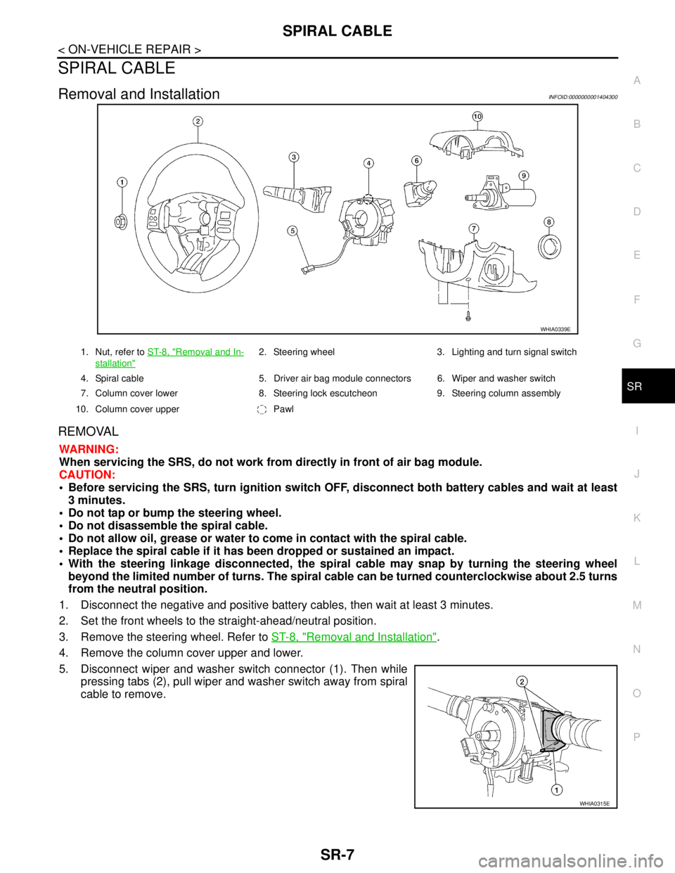
5. Disconnect wiper and washer switch connector (1). Then while
pressing tabs (2), pull wiper and washer switch away from spiral
cable to remove.
WHIA0339E
1. Nut, refer to ST-8, "Removal and In-
stallation"
2. Steering wheel 3. Lighting and turn signal switch
4. Spiral cable 5. Driver air bag module connectors 6. Wiper and washer switch
7. Column cover lower 8. Steering lock escutcheon 9. Steering column assembly
10. Column cover upper Pawl
WHIA0315E
Page 4751 of 5883

SR-8
< ON-VEHICLE REPAIR >
SPIRAL CABLE
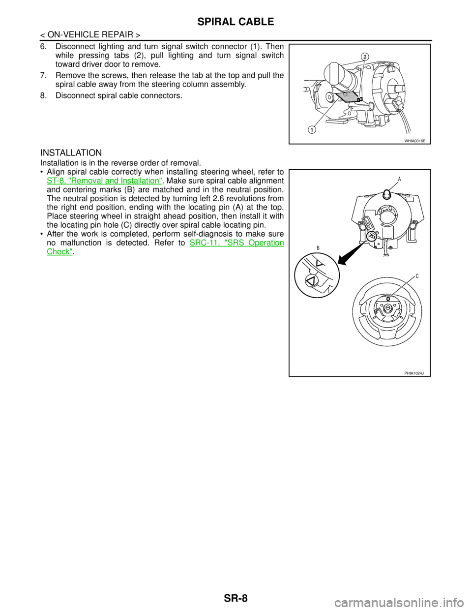
6. Disconnect lighting and turn signal switch connector (1). Then
while pressing tabs (2), pull lighting and turn signal switch
toward driver door to remove.
7. Remove the screws, then release the tab at the top and pull the
spiral cable away from the steering column assembly.
8. Disconnect spiral cable connectors.
INSTALLATION
Installation is in the reverse order of removal.
Align spiral cable correctly when installing steering wheel, refer to
ST-8, "
Removal and Installation". Make sure spiral cable alignment
and centering marks (B) are matched and in the neutral position.
The neutral position is detected by turning left 2.6 revolutions from
the right end position, ending with the locating pin (A) at the top.
Place steering wheel in straight ahead position, then install it with
the locating pin hole (C) directly over spiral cable locating pin.
After the work is completed, perform self-diagnosis to make sure
no malfunction is detected. Refer to SRC-11, "
SRS Operation
Check".
WHIA0316E
PHIA1024J
Page 4756 of 5883

PASSENGER AIR BAG DEACTIVATION SWITCH
SR-13
< ON-VEHICLE REPAIR >
C
D
E
F
G
I
J
K
L
MA
B
SR
N
O
P
PASSENGER AIR BAG DEACTIVATION SWITCH
Passenger Air Bag Deactivation SwitchINFOID:0000000001404301
REMOVAL
CAUTION:
Before servicing SRS, turn ingition switch OFF, disconnect both battery cables, then wait at least 3
minutes.
1. Disconnect the negative and positive battery cables, then wait at least 3 minutes.
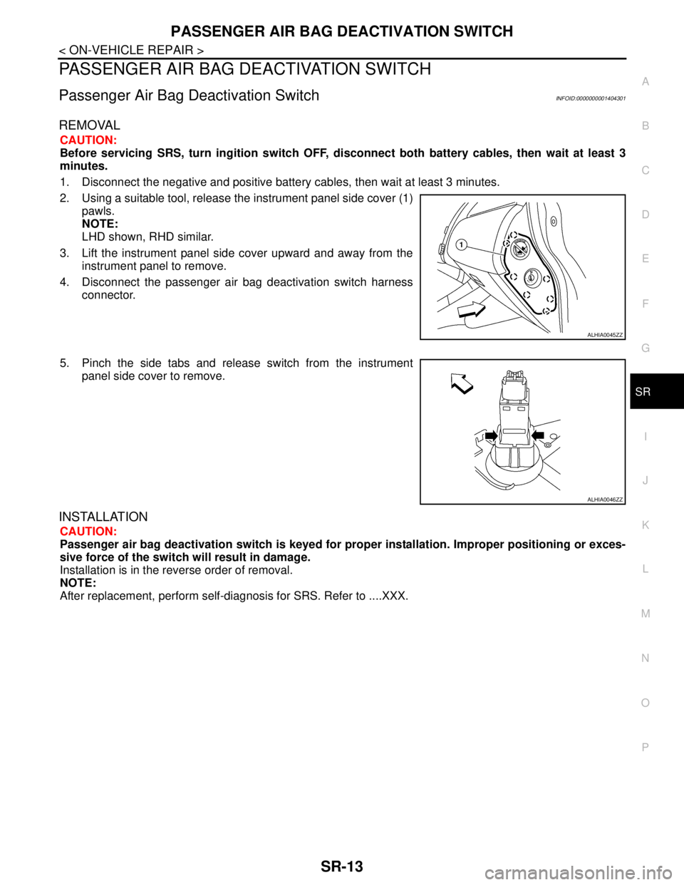
2. Using a suitable tool, release the instrument panel side cover (1)
pawls.
NOTE:
LHD shown, RHD similar.
3. Lift the instrument panel side cover upward and away from the
instrument panel to remove.
4. Disconnect the passenger air bag deactivation switch harness
connector.
5. Pinch the side tabs and release switch from the instrument
panel side cover to remove.
INSTALLATION
CAUTION:
Passenger air bag deactivation switch is keyed for proper installation. Improper positioning or exces-
sive force of the switch will result in damage.
Installation is in the reverse order of removal.
NOTE:
After replacement, perform self-diagnosis for SRS. Refer to ....XXX.
ALHIA0045ZZ
ALHIA0046ZZ
Page 4880 of 5883
![NISSAN TIIDA 2007 Service Repair Manual STC-6
< FUNCTION DIAGNOSIS >[EPS]
EPS SYSTEM
Component Description
INFOID:0000000001716729
CAN CommunicationINFOID:0000000001697716
SYSTEM DESCRIPTION
CAN (Controller Area Network) is a serial commun NISSAN TIIDA 2007 Service Repair Manual STC-6
< FUNCTION DIAGNOSIS >[EPS]
EPS SYSTEM
Component Description
INFOID:0000000001716729
CAN CommunicationINFOID:0000000001697716
SYSTEM DESCRIPTION
CAN (Controller Area Network) is a serial commun](/manual-img/5/57395/w960_57395-4879.png)
STC-6
< FUNCTION DIAGNOSIS >[EPS]
EPS SYSTEM
Component Description
INFOID:0000000001716729
CAN CommunicationINFOID:0000000001697716
SYSTEM DESCRIPTION
CAN (Controller Area Network) is a serial communication line for real time application. It is an on-vehicle mul-
tiplex communication line with high data communication speed and excellent error detection ability. Many elec-
tronic control units are equipped onto a vehicle, and each control unit shares information and links with other
control units during operation (not independent). In CAN communication, control units are connected with 2
communication lines (CAN-H line, CAN-L line) allowing a high rate of information transmission with less wiring.
Each control unit transmits/receives data but selectively reads required data only.
For details, refer to LAN-30, "
CAN System Specification Chart".
Component parts Function
EPS control unit
(Electric power steering control unit) Outputs optimum assist torque signal to EPS motor.
Reduces output signals to EPS motor and protects EPS motor and EPS control unit when us-
ing power steering continuously and excessively.
As a fail-safe function, turned off output signal to EPS motor and then enters a manual steer-
ing state, if malfunction is detected in EPS system.
EPS motor Products assist torque by control signal from EPS control unit.
Torque sensor Detects steering wheel turning force and outputs sensor signal to EPS control unit.
Reduction gear Increases motor-produced assist torque by worm gear and transmits it to column shaft.
EPS warning lamp Illuminates if malfunction is detected in electrical system of EPS system.
ECMTransmits the following signals via CAN communication to EPS control unit.
Engine status signal
ABS actuator and electric unit (con-
trol unit)Transmits the following signals via CAN communication to EPS control unit.
Vehicle speed signal
Combination meterTransmits the following signals via CAN communication to EPS control unit.
Vehicle speed signal