2007 NISSAN TIIDA body interior
[x] Cancel search: body interiorPage 1 of 5883

MODEL C11 SERIES
2007 NISSAN EUROPE S.A.S.
All rights reserved. No part of this Electronic Service Manual may be reproduced or stored in a retrieval system, or transmitted in any form,
or by any means, electronic, mechanical, photocopying, recording or otherwise, without the prior written permission of Nissan Europe
S.A.S., Paris, France.
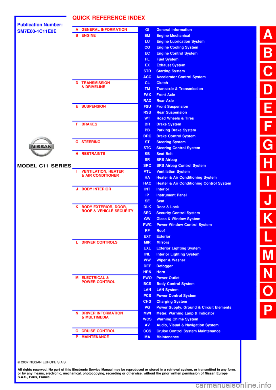
A GENERAL INFORMATION
B ENGINE
D TRANSMISSION& DRIVELINE
E SUSPENSION F BRAKES
G STEERING H RESTRAINTS
I VENTILATION, HEATER & AIR CONDITIONER
J BODY INTERIOR
K BODY EXTERIOR, DOOR, ROOF & VEHICLE SECURITY
L DRIVER CONTROLS
M ELECTRICAL & POWER CONTROL
N DRIVER INFORMATION & MULTIMEDIA
O CRUISE CONTROL P MAINTENANCEGI General Information
EM Engine Mechanical
LU Engine Lubrication System
CO Engine Cooling System
EC Engine Control System
FL Fuel System
EX Exhaust System
STR Starting System
ACC Accelerator Control System
CL Clutch
TM Transaxle & Transmission
FAX Front Axle
RAX Rear Axle
FSU Front Suspension
RSU Rear Suspension
WT Road Wheels & Tires
BR Brake System
PB Parking Brake System
BRC Brake Control System
ST Steering System
STC Steering Control System
SB Seat Belt
SR SRS Airbag
SRC SRS Airbag Control System
VTL Ventilation System
HA Heater & Air Conditioning System
HAC Heater & Air Conditioning Control System
INT Interior
IP Instrument Panel
SE Seat
DLK Door & Lock
SEC Security Control System
GW Glass & Window System
PWC Power Window Control System
RF Roof
EXT Exterior
MIR Mirrors
EXL Exterior Lighting System
INL Interior Lighting System
WW Wiper & Washer
DEF Defogger
HRN Horn
PWO Power Outlet
BCS Body Control System
LAN LAN System
PCS Power Control System
CHG Charging System
PG Power Supply, Ground & Circuit Elements
MWI Meter, Warning Lanp & Indicator
WCS Warning Chime System
AV Audio, Visual & Navigation System
CCS Cruise Control System Maintenance
MA Maintenance
QUICK REFERENCE INDEX
A
B
C
D
E
F
G
H
I
J
K
L
M
N
O
P
M
Publication Number:
SM7E00-1C11E0E
Page 142 of 5883

BCS
BODY CONTROL SYSTEM
BCS-7
< FUNCTION DIAGNOSIS >
C
D
E
F
G
H
I
J
K
L B A
O
P N
FUNCTION DIAGNOSIS
BODY CONTROL SYSTEM
System DescriptionINFOID:0000000001451453
OUTLINE
BCM (Body Control Module) controls the various electrical components. It inputs the information required to
the control from CAN communication and the signal received from each switch and sensor.
BCM has combination switch reading function for reading the operation status of combination switches (light,
turn signal, wiper and washer) in addition to a function for controlling the operation of various electrical com-
ponents. It also has the signal transmission function as the passed point of signal and the power consump-
tion control function that reduces the power consumption with the ignition switch OFF.
BCM is equipped with the diagnosis function that performs the diagnosis with CONSULT-III and various set-
tings.
BCM control function list
System Refer to
Combination switch reading systemBCS-9, "
System Diagram"
Signal buffer systemBCS-13, "System Diagram"
Power consumption control systemBCS-14, "System Diagram"
Auto light systemEXL-12, "System Diagram"
Turn signal and hazard warning lamp systemEXL-22, "System Diagram"
Headlamp systemEXL-8, "System Diagram"
Front fog lamp systemEXL-19, "System Diagram"
Rear fog lamp systemEXL-21, "System Diagram"
Daytime light systemEXL-17, "System Diagram"
Interior room lamp control systemINL-5, "System Diagram"
Interior room lamp battery saver systemINL-12, "BATTERY SAVER : CONSULT-III Function (BCM - BATTERY SAV-
ER)"
Front wiper and washer systemWW-4, "System Diagram"
Rear wiper and washer systemWW-9, "System Diagram"
Headlamp washer systemWW-12, "System Diagram"
Warning chime systemWCS-4, "WARNING CHIME SYSTEM : System Diagram"
Door lock system WITH I-KEY, WITHOUT SUPER LOCK: DLK-20, "
DOOR LOCK AND UN-
LOCK SWITCH : System Diagram"
WITH I-KEY & SUPER LOCK: DLK-244, "DOOR LOCK AND UNLOCK
SWITCH : System Diagram"
WITHOUT I-KEY & SUPER LOCK: DLK-473, "DOOR LOCK AND UN-
LOCK SWITCH : System Diagram"
WITHOUT I-KEY, WITH SUPER LOCK: DLK-614, "DOOR LOCK AND UN-
LOCK SWITCH : System Diagram"
(NATS) Nissan anti-theft system WITH INTELLIGENT KEY SYSTEM: SEC-12, "System Diagram"
WITHOUT INTELLIGENT KEY SYSTEM: SEC-84, "System Diagram"
Rear window defogger systemDEF-6, "System Diagram"
Remote keyless entry system WITHOUT I-KEY & SUPER LOCK: DLK-475, "
REMOTE KEYLESS EN-
TRY : System Diagram"
WITHOUT I-KEY, WITH SUPER LOCK: DLK-614, "DOOR LOCK AND UN-
LOCK SWITCH : System Diagram"
Intelligent Key system WITH I-KEY, WITHOUT SUPER LOCK: DLK-23, "
INTELLIGENT KEY :
System Diagram"
WITH I-KEY & SUPER LOCK: DLK-244, "DOOR LOCK AND UNLOCK
SWITCH : System Diagram"
Page 178 of 5883

BCS
BCM (BODY CONTROL MODULE)
BCS-43
< ECU DIAGNOSIS >
C
D
E
F
G
H
I
J
K
L B A
O
P N
13
(V)GroundCombination switch
OUTPUT 1OutputCombination
switchAll switch OFF
(Wiper intermittent dial 4)0V
Front wiper switch HI
(Wiper intermittent dial 4)
Rear wiper switch INT
(Wiper intermittent dial 4)
Any of the condition below
with all switch OFF
Wiper intermittent dial 1
Wiper intermittent dial 2
Wiper intermittent dial 3
Wiper intermittent dial 6
Wiper intermittent dial 7
14
(L)GroundCombination switch
OUTPUT 3OutputCombination
switch
(Wiper intermit-
tent dial 4)All switch OFF 0V
Lighting switch AUTO
Rear fog lamp switch OFF
Front wiper switch MIST
Front wiper switch INT
Front wiper switch LO
15
(BR)GroundCombination switch
OUTPUT 5OutputCombination
switch
(Wiper intermit-
tent dial 4)All switch OFF 0V
Lighting switch 1ST
Lighting switch 2ND
Lighting switch HI
Turn signal switch RH
16
(R)Ground Stop lamp switch InputDepress the brake pedal Battery voltage
Release the brake pedal 0V
17
(Y)Ground Back up lamp signal InputShift lever in reverse Battery voltage
Other than above 0V
19
(L)—CAN-HInput/
Output——
21
(BR)GroundRoom lamp timer
controlOutputInterior room
lampOFF Battery voltage
ON 0V
22
(P)GroundBattery power sup-
plyInput — Battery voltage
23
1
(LG)Ground Rear wiper auto stop OutputIgnition switch
ONRear wiper stop position 0V
Any position other than
rear wiper stop position Terminal No.
(Wire color)Description
ConditionReference Value
(Approx.)
Signal nameInput/
Output +−
SKIA2167J
SKIA2167J
SKIA2167J
JPMIA0197GB
Page 184 of 5883

BCS
BCM (BODY CONTROL MODULE)
BCS-49
< ECU DIAGNOSIS >
C
D
E
F
G
H
I
J
K
L B A
O
P N
1: Hatchback
2: Sedan
3: Manual A/C
4: Superlock
5: Remote keyless entry
6: Intelligent Key
7: LHD diesel69
(G)Ground Rear fog lamp OutputLighting switch
1ST and front
fog lamp switch
ONRear fog lamp switch OFF 0V
Rear fog lamp switch ON Battery voltage
70
(B)Ground Ground — — 0V
71
1
(V)Ground Rear wiper motor OutputRear wiper switch OFF 0V
Rear wiper switch ON Battery voltage
72
(LG)GroundBattery power sup-
plyInput — Battery voltage
73
(R)GroundInterior room lamp
power supplyOutputAfter passing the interior room lamp battery
saver operation time0V
Any other time after passing the interior room
lamp battery saver operation timeBattery voltage
74
(Y)GroundBattery power sup-
plyInput — Battery voltage
75
4
(V)Ground Super lock OutputWhen lock button of keyfob or Intelligent Key
is not pressed 0V
When lock button of keyfob or Intelligent Key
is pressed Battery voltage
76
(G)Ground Driver door unlock OutputDoor lock/un-
lock switchPressed to the unlock side Battery voltage
Pressed to the lock side 0V
77
(SB)Ground Door lock (All) OutputDoor lock/un-
lock switchPressed to the unlock side 0V
Pressed to the lock side Battery voltage
78
(L)GroundPower window pow-
er supplyOutput Ignition switchOFF or ACC 0V
ON Battery voltage
79
(Y)GroundBattery power sup-
plyInput — Battery voltage Terminal No.
(Wire color)Description
ConditionReference Value
(Approx.)
Signal nameInput/
Output +−
Page 3292 of 5883

HA-10
< PRECAUTION >
PRECAUTIONS
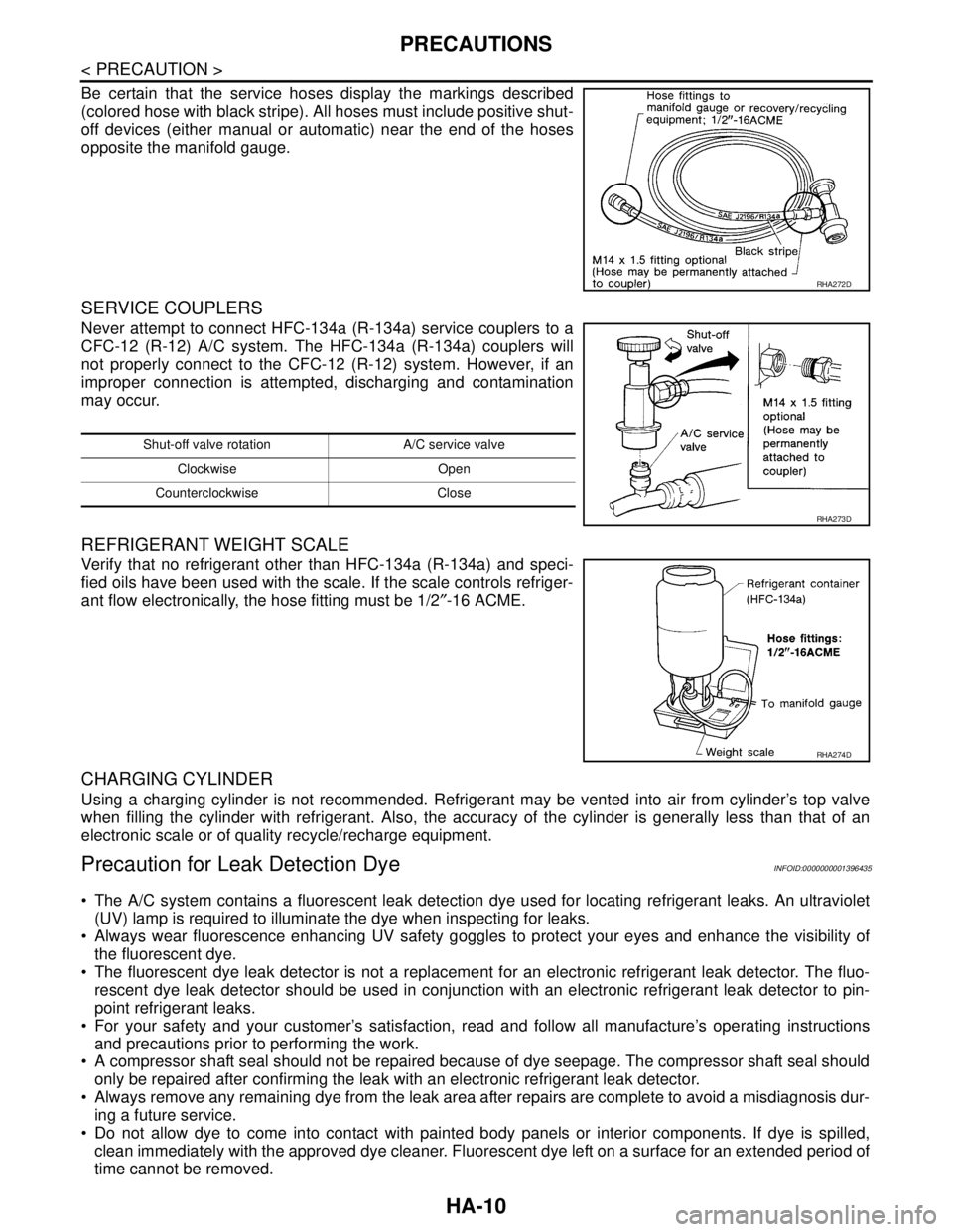
Be certain that the service hoses display the markings described
(colored hose with black stripe). All hoses must include positive shut-
off devices (either manual or automatic) near the end of the hoses
opposite the manifold gauge.
SERVICE COUPLERS
Never attempt to connect HFC-134a (R-134a) service couplers to a
CFC-12 (R-12) A/C system. The HFC-134a (R-134a) couplers will
not properly connect to the CFC-12 (R-12) system. However, if an
improper connection is attempted, discharging and contamination
may occur.
REFRIGERANT WEIGHT SCALE
Verify that no refrigerant other than HFC-134a (R-134a) and speci-
fied oils have been used with the scale. If the scale controls refriger-
ant flow electronically, the hose fitting must be 1/2″-16 ACME.
CHARGING CYLINDER
Using a charging cylinder is not recommended. Refrigerant may be vented into air from cylinder’s top valve
when filling the cylinder with refrigerant. Also, the accuracy of the cylinder is generally less than that of an
electronic scale or of quality recycle/recharge equipment.
Precaution for Leak Detection DyeINFOID:0000000001396435
The A/C system contains a fluorescent leak detection dye used for locating refrigerant leaks. An ultraviolet
(UV) lamp is required to illuminate the dye when inspecting for leaks.
Always wear fluorescence enhancing UV safety goggles to protect your eyes and enhance the visibility of
the fluorescent dye.
The fluorescent dye leak detector is not a replacement for an electronic refrigerant leak detector. The fluo-
rescent dye leak detector should be used in conjunction with an electronic refrigerant leak detector to pin-
point refrigerant leaks.
For your safety and your customer’s satisfaction, read and follow all manufacture’s operating instructions
and precautions prior to performing the work.
A compressor shaft seal should not be repaired because of dye seepage. The compressor shaft seal should
only be repaired after confirming the leak with an electronic refrigerant leak detector.
Always remove any remaining dye from the leak area after repairs are complete to avoid a misdiagnosis dur-
ing a future service.
Do not allow dye to come into contact with painted body panels or interior components. If dye is spilled,
clean immediately with the approved dye cleaner. Fluorescent dye left on a surface for an extended period of
time cannot be removed.
RHA272D
Shut-off valve rotation A/C service valve
Clockwise Open
Counterclockwise Close
RHA273D
RHA274D
Page 3652 of 5883

INL-1
DRIVER CONTROLS
C
D
E
F
G
H
I
J
K
M
SECTION INL
A
B
INL
N
O
P
CONTENTS
INTERIOR LIGHTING SYSTEM
BASIC INSPECTION ....................................2
DIAGNOSIS AND REPAIR WORKFLOW ..........2
Work Flow .................................................................2
FUNCTION DIAGNOSIS ...............................5
INTERIOR ROOM LAMP CONTROL SYSTEM
.....
5
System Diagram ........................................................5
System Description ...................................................5
Component Parts Location ........................................6
Component Description ............................................6
ILLUMINATION CONTROL SYSTEM .................8
System Diagram ........................................................8
System Description ...................................................8
Component Parts Location ........................................8
Component Description .............................................9
DIAGNOSIS SYSTEM (BCM) ............................10
COMMON ITEM .........................................................10
COMMON ITEM : CONSULT-III Function (BCM -
COMMON ITEM) .....................................................
10
INT LAMP ..................................................................10
INT LAMP : CONSULT-III Function (BCM - INT
LAMP) .....................................................................
10
BATTERY SAVER .....................................................12
BATTERY SAVER : CONSULT-III Function (BCM
- BATTERY SAVER) ...............................................
12
COMPONENT DIAGNOSIS .........................14
POWER SUPPLY AND GROUND CIRCUIT ......14
BCM ...........................................................................14
BCM : Diagnosis Procedure ....................................14
INTERIOR ROOM LAMP POWER SUPPLY
CIRCUIT ............................................................
15
Description ...............................................................15
Component Function Check ....................................15
Diagnosis Procedure ...............................................15
INTERIOR ROOM LAMP CONTROL SYSTEM
...
17
Wiring Diagram - INTERIOR ROOM LAMP - ..........17
ILLUMINATION .................................................20
Wiring Diagram - ILLUMINATION - .........................20
ECU DIAGNOSIS .........................................22
BCM (BODY CONTROL MODULE) .................22
Description ...............................................................22
SYMPTOM DIAGNOSIS ..............................23
INTERIOR LIGHTING SYSTEM SYMPTOMS ...23
Symptom Table .......................................................23
PRECAUTION ..............................................24
PRECAUTIONS .................................................24
Supplemental Restraint System (SRS) "AIR BAG"
and "SEAT BELT PRE-TENSIONER" .....................
24
General precautions for service operations .............24
ON-VEHICLE REPAIR .................................25
INTERIOR ROOM LAMP ..................................25
Removal and Installation .........................................25
SERVICE DATA AND SPECIFICATIONS
(SDS) ............................................................
28
SERVICE DATA AND SPECIFICATIONS
(SDS) .................................................................
28
Bulb Specifications ..................................................28
Page 3678 of 5883

INTERIOR ROOM LAMP
INL-27
< ON-VEHICLE REPAIR >
C
D
E
F
G
H
I
J
K
MA
B
INL
N
O
P
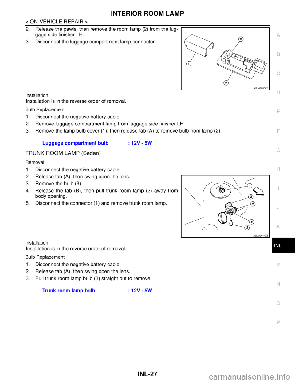
2. Release the pawls, then remove the room lamp (2) from the lug-
gage side finisher LH.
3. Disconnect the luggage compartment lamp connector.
Installation
Installation is in the reverse order of removal.
Bulb Replacement
1. Disconnect the negative battery cable.
2. Remove luggage compartment lamp from luggage side finisher LH.
3. Remove the lamp bulb cover (1), then release tab (A) to remove bulb from lamp (2).
TRUNK ROOM LAMP (Sedan)
Removal
1. Disconnect the negative battery cable.
2. Release tab (A), then swing open the lens.
3. Remove the bulb (3).
4. Release the tab (B), then pull trunk room lamp (2) away from
body opening.
5. Disconnect the connector (1) and remove trunk room lamp.
Installation
Installation is in the reverse order of removal.
Bulb Replacement
1. Disconnect the negative battery cable.
2. Release tab (A), then swing open the lens.
3. Pull trunk room lamp bulb (3) straight out to remove.
ALLIA0655ZZ
Luggage compartment bulb : 12V - 5W
ALLIA0014ZZ
Trunk room lamp bulb : 12V - 5W
Page 3680 of 5883

INT-1
BODY INTERIOR
C
D
E
F
G
H
I
K
L
M
SECTION INT
A
B
INT
N
O
P
CONTENTS
INTERIOR
PRECAUTION ...............................................2
PRECAUTIONS ...................................................2
Precaution for Supplemental Restraint System
(SRS) "AIR BAG" and "SEAT BELT PRE-TEN-
SIONER" ...................................................................
2
Precaution .................................................................2
PREPARATION ............................................3
PREPARATION ...................................................3
Commercial Service Tool ..........................................3
CLIP AND FASTENER ........................................4
Description ................................................................4
SQUEAK AND RATTLE TROUBLE DIAGNO-
SIS .......................................................................
7
Work Flow .................................................................7
Generic Squeak and Rattle Troubleshooting ............9
Diagnostic Worksheet .............................................11
ON-VEHICLE REPAIR .................................13
DOOR FINISHER ...............................................13
Removal and Installation .........................................13
TRUNK LID FINISHER ......................................17
Removal and Installation .........................................17
BACK DOOR TRIM ...........................................18
Removal and Installation .........................................18
BODY SIDE TRIM .............................................19
Component ..............................................................19
Removal and Installation .........................................20
LUGGAGE FLOOR TRIM .................................24
Removal and Installation .........................................24
REAR PARCEL SHELF FINISHER ..................26
Removal and Installation .........................................26
FLOOR TRIM ....................................................27
Removal and Installation .........................................27
HEADLINING ....................................................29
Component ..............................................................29
Removal and Installation - Hatchback .....................31
Removal and Installation - Sedan ............................33
TRUNK ROOM TRIM & TRUNK LID FINISH-
ER ......................................................................
35
Removal and Installation .........................................35