2007 NISSAN TIIDA turn signal bulb
[x] Cancel search: turn signal bulbPage 158 of 5883

BCS
DIAGNOSIS SYSTEM (BCM)
BCS-23
< FUNCTION DIAGNOSIS >
C
D
E
F
G
H
I
J
K
L B A
O
P N
ACTIVE TEST
AIR CONDITIONER
AIR CONDITIONER : CONSULT-III Function (BCM - AUTO AIR CONDITIONER)
INFOID:0000000001451473
ACTIVE TEST
DATA MONITOR
INTELLIGENT KEY
INTELLIGENT KEY : CONSULT-III Function (BCM - INTELLIGENT KEY)INFOID:0000000001451474
DATA MONITOR
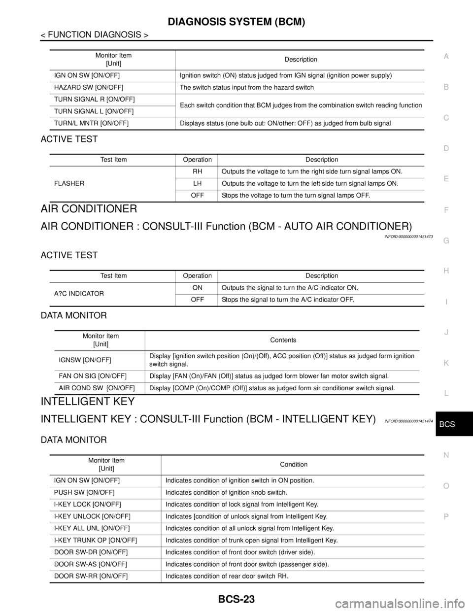
Monitor Item
[Unit]Description
IGN ON SW [ON/OFF] Ignition switch (ON) status judged from IGN signal (ignition power supply)
HAZARD SW [ON/OFF] The switch status input from the hazard switch
TURN SIGNAL R [ON/OFF]
Each switch condition that BCM judges from the combination switch reading function
TURN SIGNAL L [ON/OFF]
TURN/L MNTR [ON/OFF] Displays status (one bulb out: ON/other: OFF) as judged from bulb signal
Test Item Operation Description
FLASHERRH Outputs the voltage to turn the right side turn signal lamps ON.
LH Outputs the voltage to turn the left side turn signal lamps ON.
OFF Stops the voltage to turn the turn signal lamps OFF.
Test Item Operation Description
A?C INDICATORON Outputs the signal to turn the A/C indicator ON.
OFF Stops the signal to turn the A/C indicator OFF.
Monitor Item
[Unit]Contents
IGNSW [ON/OFF]Display [ignition switch position (On)/(Off), ACC position (Off)] status as judged form ignition
switch signal.
FAN ON SIG [ON/OFF] Display [FAN (On)/FAN (Off)] status as judged form blower fan motor switch signal.
AIR COND SW [ON/OFF] Display [COMP (On)/COMP (Off)] status as judged form air conditioner switch signal.
Monitor Item
[Unit]Condition
IGN ON SW [ON/OFF] Indicates condition of ignition switch in ON position.
PUSH SW [ON/OFF] Indicates condition of ignition knob switch.
I-KEY LOCK [ON/OFF] Indicates condition of lock signal from Intelligent Key.
I-KEY UNLOCK [ON/OFF] Indicates [condition of unlock signal from Intelligent Key.
I-KEY ALL UNL [ON/OFF] Indicates condition of all unlock signal from Intelligent Key.
I-KEY TRUNK OP [ON/OFF] Indicates condition of trunk open signal from Intelligent Key.
DOOR SW-DR [ON/OFF] Indicates condition of front door switch (driver side).
DOOR SW-AS [ON/OFF] Indicates condition of front door switch (passenger side).
DOOR SW-RR [ON/OFF] Indicates condition of rear door switch RH.
Page 778 of 5883
![NISSAN TIIDA 2007 Service Repair Manual BCM (BODY CONTROL MODULE)
DLK-189
< ECU DIAGNOSIS >[WITH I-KEY, WITHOUT SUPER LOCK]
C
D
E
F
G
H
I
J
L
MA
B
DLK
N
O
P
TURN SIGNAL LAMP CONTROL
BCM detects the turn signal lamp circuit status from the t NISSAN TIIDA 2007 Service Repair Manual BCM (BODY CONTROL MODULE)
DLK-189
< ECU DIAGNOSIS >[WITH I-KEY, WITHOUT SUPER LOCK]
C
D
E
F
G
H
I
J
L
MA
B
DLK
N
O
P
TURN SIGNAL LAMP CONTROL
BCM detects the turn signal lamp circuit status from the t](/manual-img/5/57395/w960_57395-777.png)
BCM (BODY CONTROL MODULE)
DLK-189
< ECU DIAGNOSIS >[WITH I-KEY, WITHOUT SUPER LOCK]
C
D
E
F
G
H
I
J
L
MA
B
DLK
N
O
P
TURN SIGNAL LAMP CONTROL
BCM detects the turn signal lamp circuit status from the terminal voltage.
BCM increases the turn signal lamp blinking speed if the bulb or harness open is detected with the turn signal
lamp operating.
NOTE:
The blinking speed is normal while activating the hazard warning lamp.
LIGHT & RAIN SENSOR MALFUNCTION DETECTION FUNCTION
BCM controls the following items when LIGHT & RAIN sensor has a malfunction.
Auto Light Control
Headlamp is turned ON.
Front Wiper Control
The condition just before the activation of Fail-safe is maintained until the front wiper switch is turned OFF.
DTC Inspection Priority ChartINFOID:0000000001396648
DTC IndexINFOID:0000000001396649
NOTE:
Details of time display
CRNT: Displays when there is a malfunction now or after returning to the normal condition until turning igni-
tion switch OFF → ON again.
PAST: Displays when there is a malfunction that is detected in the past and stored.
1 - 39: Displayed if any previous malfunction is present when current condition is normal. It increases like 1
→ 2 → 3...38 → 39 after returning to the normal condition whenever ignition switch OFF → ON. The counter
remains at 39 even if the number of cycles exceeds it. It is counted from 1 again when turning ignition switch
OFF → ON after returning to the normal condition if the malfunction is detected again.
Display contents of CONSULT Fail-safe Cancellation
B2190: NATS ANTENNA AMP Inhibits engine cranking
Inhibits steering lock unlocking (Intelligent Key unit)
Fuel cut (ECM)Erase DTC
B2191: DIFFERENCE OF KEY Inhibits engine cranking
Inhibits steering lock unlocking (Intelligent Key unit)
Fuel cut (ECM)Erase DTC
B2192: ID DISCORD BCM-ECM Fuel cut (ECM) Erase DTC
B2193: CHAIN OF BCM-ECM Fuel cut (ECM) Erase DTC
B2194: DISCORD BCM-I-KEY Inhibits engine cranking
Inhibits steering lock unlocking (Intelligent Key unit)
Fuel cut (ECM)Erase DTC
B2195: ANTI SCANNING Inhibits engine cranking
Inhibits steering lock unlocking (Intelligent Key unit)
Fuel cut (ECM)Erase DTC
B2196: DONGLE NG Inhibits engine cranking
Inhibits steering lock unlocking (Intelligent Key unit)
Fuel cut (ECM)Erase DTC
Priority DTC
1 U1000: CAN COMM CIRCUIT
U1010: CONTROL UNIT (CAN)
2 B2190: NATS ANTENNA AMP
B2191: DIFFERNCE OF KEY
B2192: ID DISCORD BCM-ECM
B2193: CHAIN OF BCM-ECM
B2194: DISCORD BCM-I-KEY
B2195: ANTI SCANNING
B2196: DONGLE NG
Page 1007 of 5883
![NISSAN TIIDA 2007 Service Repair Manual DLK-418
< ECU DIAGNOSIS >[WITH I-KEY & SUPER LOCK]
BCM (BODY CONTROL MODULE)
TURN SIGNAL LAMP CONTROL
BCM detects the turn signal lamp circuit status from the terminal voltage.
BCM increases the turn NISSAN TIIDA 2007 Service Repair Manual DLK-418
< ECU DIAGNOSIS >[WITH I-KEY & SUPER LOCK]
BCM (BODY CONTROL MODULE)
TURN SIGNAL LAMP CONTROL
BCM detects the turn signal lamp circuit status from the terminal voltage.
BCM increases the turn](/manual-img/5/57395/w960_57395-1006.png)
DLK-418
< ECU DIAGNOSIS >[WITH I-KEY & SUPER LOCK]
BCM (BODY CONTROL MODULE)
TURN SIGNAL LAMP CONTROL
BCM detects the turn signal lamp circuit status from the terminal voltage.
BCM increases the turn signal lamp blinking speed if the bulb or harness open is detected with the turn signal
lamp operating.
NOTE:
The blinking speed is normal while activating the hazard warning lamp.
LIGHT & RAIN SENSOR MALFUNCTION DETECTION FUNCTION
BCM controls the following items when LIGHT & RAIN sensor has a malfunction.
Auto Light Control
Headlamp is turned ON.
Front Wiper Control
The condition just before the activation of Fail-safe is maintained until the front wiper switch is turned OFF.
DTC Inspection Priority ChartINFOID:0000000001530554
DTC IndexINFOID:0000000001530555
NOTE:
Details of time display
CRNT: Displays when there is a malfunction now or after returning to the normal condition until turning igni-
tion switch OFF → ON again.
PAST: Displays when there is a malfunction that is detected in the past and stored.
1 - 39: Displayed if any previous malfunction is present when current condition is normal. It increases like 1
→ 2 → 3...38 → 39 after returning to the normal condition whenever ignition switch OFF → ON. The counter
remains at 39 even if the number of cycles exceeds it. It is counted from 1 again when turning ignition switch
OFF → ON after returning to the normal condition if the malfunction is detected again.
Display contents of CONSULT Fail-safe Cancellation
B2190: NATS ANTENNA AMP Inhibits engine cranking
Inhibits steering lock unlocking (Intelligent Key unit)
Fuel cut (ECM)Erase DTC
B2191: DIFFERENCE OF KEY Inhibits engine cranking
Inhibits steering lock unlocking (Intelligent Key unit)
Fuel cut (ECM)Erase DTC
B2192: ID DISCORD BCM-ECM Fuel cut (ECM) Erase DTC
B2193: CHAIN OF BCM-ECM Fuel cut (ECM) Erase DTC
B2194: DISCORD BCM-I-KEY Inhibits engine cranking
Inhibits steering lock unlocking (Intelligent Key unit)
Fuel cut (ECM)Erase DTC
B2195: ANTI SCANNING Inhibits engine cranking
Inhibits steering lock unlocking (Intelligent Key unit)
Fuel cut (ECM)Erase DTC
B2196: DONGLE NG Inhibits engine cranking
Inhibits steering lock unlocking (Intelligent Key unit)
Fuel cut (ECM)Erase DTC
Priority DTC
1 U1000: CAN COMM CIRCUIT
U1010: CONTROL UNIT (CAN)
2 B2190: NATS ANTENNA AMP
B2191: DIFFERNCE OF KEY
B2192: ID DISCORD BCM-ECM
B2193: CHAIN OF BCM-ECM
B2194: DISCORD BCM-I-KEY
B2195: ANTI SCANNING
B2196: DONGLE NG
Page 1154 of 5883
![NISSAN TIIDA 2007 Service Repair Manual BCM (BODY CONTROL MODULE)
DLK-565
< ECU DIAGNOSIS >[WITHOUT I-KEY & SUPER LOCK]
C
D
E
F
G
H
I
J
L
MA
B
DLK
N
O
P
TURN SIGNAL LAMP CONTROL
BCM detects the turn signal lamp circuit status from the termi NISSAN TIIDA 2007 Service Repair Manual BCM (BODY CONTROL MODULE)
DLK-565
< ECU DIAGNOSIS >[WITHOUT I-KEY & SUPER LOCK]
C
D
E
F
G
H
I
J
L
MA
B
DLK
N
O
P
TURN SIGNAL LAMP CONTROL
BCM detects the turn signal lamp circuit status from the termi](/manual-img/5/57395/w960_57395-1153.png)
BCM (BODY CONTROL MODULE)
DLK-565
< ECU DIAGNOSIS >[WITHOUT I-KEY & SUPER LOCK]
C
D
E
F
G
H
I
J
L
MA
B
DLK
N
O
P
TURN SIGNAL LAMP CONTROL
BCM detects the turn signal lamp circuit status from the terminal voltage.
BCM increases the turn signal lamp blinking speed if the bulb or harness open is detected with the turn signal
lamp operating.
NOTE:
The blinking speed is normal while activating the hazard warning lamp.
DTC Inspection Priority ChartINFOID:0000000001397105
DTC IndexINFOID:0000000001397106
NOTE:
Details of time display
CRNT: Displays when there is a malfunction now or after returning to the normal condition until turning igni-
tion switch OFF → ON again.
PAST: Displays when there is a malfunction that is detected in the past and stored.
1 - 39: Displayed if any previous malfunction is present when current condition is normal. It increases like 1
→ 2 → 3...38 → 39 after returning to the normal condition whenever ignition switch OFF → ON. The counter
remains at 39 even if the number of cycles exceeds it. It is counted from 1 again when turning ignition switch
OFF → ON after returning to the normal condition if the malfunction is detected again.
Display contents of CONSULT Fail-safe Cancellation
B2190: NATS ANTENNA AMP Inhibits engine cranking
Fuel cut (ECM)Erase DTC
B2191: DIFFERENCE OF KEY Inhibits engine cranking
Fuel cut (ECM)Erase DTC
B2192: ID DISCORD BCM-ECM Fuel cut (ECM) Erase DTC
B2193: CHAIN OF BCM-ECM Fuel cut (ECM) Erase DTC
B2194: DISCORD BCM-I-KEY Inhibits engine cranking
Fuel cut (ECM)Erase DTC
B2195: ANTI SCANNING Inhibits engine cranking
Fuel cut (ECM)Erase DTC
B2196: DONGLE NG Inhibits engine cranking
Fuel cut (ECM)Erase DTC
Priority DTC
1 U1000: CAN COMM CIRCUIT
U1010: CONTROL UNIT (CAN)
2 B2190: NATS ANTENNA AMP
B2191: DIFFERNCE OF KEY
B2192: ID DISCORD BCM-ECM
B2193: CHAIN OF BCM-ECM
B2194: DISCORD BCM-I-KEY
B2195: ANTI SCANNING
B2196: DONGLE NG
CONSULT display TIME Fail-safe Refer to
No DTC is detected.
further testing
may be required.—— — —
U1000: CAN COMM CIRCUIT 0 1 - 39 —XX-XX, "*****"
U1010: CONTROL UNIT (CAN) 0 1 - 39 —XX-XX, "*****"
B2190: NATS ANTENNA AMP CRNT PAST×XX-XX, "*****"
B2191: DIFFERENCE OF KEY CRNT PAST×XX-XX, "*****"
B2192: ID DISCORD BCM-ECM CRNT PAST×XX-XX, "*****"
Page 1305 of 5883
![NISSAN TIIDA 2007 Service Repair Manual DLK-716
< ECU DIAGNOSIS >[WITHOUT I-KEY, WITH SUPER LOCK]
BCM (BODY CONTROL MODULE)
TURN SIGNAL LAMP CONTROL
BCM detects the turn signal lamp circuit status from the terminal voltage.
BCM increases th NISSAN TIIDA 2007 Service Repair Manual DLK-716
< ECU DIAGNOSIS >[WITHOUT I-KEY, WITH SUPER LOCK]
BCM (BODY CONTROL MODULE)
TURN SIGNAL LAMP CONTROL
BCM detects the turn signal lamp circuit status from the terminal voltage.
BCM increases th](/manual-img/5/57395/w960_57395-1304.png)
DLK-716
< ECU DIAGNOSIS >[WITHOUT I-KEY, WITH SUPER LOCK]
BCM (BODY CONTROL MODULE)
TURN SIGNAL LAMP CONTROL
BCM detects the turn signal lamp circuit status from the terminal voltage.
BCM increases the turn signal lamp blinking speed if the bulb or harness open is detected with the turn signal
lamp operating.
NOTE:
The blinking speed is normal while activating the hazard warning lamp.
DTC Inspection Priority ChartINFOID:0000000001397330
DTC IndexINFOID:0000000001397331
NOTE:
Details of time display
CRNT: Displays when there is a malfunction now or after returning to the normal condition until turning igni-
tion switch OFF → ON again.
PAST: Displays when there is a malfunction that is detected in the past and stored.
1 - 39: Displayed if any previous malfunction is present when current condition is normal. It increases like 1
→ 2 → 3...38 → 39 after returning to the normal condition whenever ignition switch OFF → ON. The counter
remains at 39 even if the number of cycles exceeds it. It is counted from 1 again when turning ignition switch
OFF → ON after returning to the normal condition if the malfunction is detected again.
Display contents of CONSULT Fail-safe Cancellation
B2190: NATS ANTENNA AMP Inhibits engine cranking
Fuel cut (ECM)Erase DTC
B2191: DIFFERENCE OF KEY Inhibits engine cranking
Fuel cut (ECM)Erase DTC
B2192: ID DISCORD BCM-ECM Fuel cut (ECM) Erase DTC
B2193: CHAIN OF BCM-ECM Fuel cut (ECM) Erase DTC
B2194: DISCORD BCM-I-KEY Inhibits engine cranking
Fuel cut (ECM)Erase DTC
B2195: ANTI SCANNING Inhibits engine cranking
Fuel cut (ECM)Erase DTC
B2196: DONGLE NG Inhibits engine cranking
Fuel cut (ECM)Erase DTC
Priority DTC
1 U1000: CAN COMM CIRCUIT
U1010: CONTROL UNIT (CAN)
2 B2190: NATS ANTENNA AMP
B2191: DIFFERNCE OF KEY
B2192: ID DISCORD BCM-ECM
B2193: CHAIN OF BCM-ECM
B2194: DISCORD BCM-I-KEY
B2195: ANTI SCANNING
B2196: DONGLE NG
CONSULT display TIME Fail-safe Refer to
No DTC is detected.
further testing
may be required.—— — —
U1000: CAN COMM CIRCUIT 0 1 - 39 —XX-XX, "*****"
U1010: CONTROL UNIT (CAN) 0 1 - 39 —XX-XX, "*****"
B2190: NATS ANTENNA AMP CRNT PAST×XX-XX, "*****"
B2191: DIFFERENCE OF KEY CRNT PAST×XX-XX, "*****"
B2192: ID DISCORD BCM-ECM CRNT PAST×XX-XX, "*****"
Page 3004 of 5883

EXL-3
C
D
E
F
G
H
I
J
K
MA
B
EXL
N
O
P
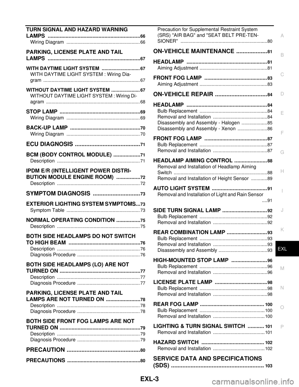
TURN SIGNAL AND HAZARD WARNING
LAMPS ...............................................................
66
Wiring Diagram .......................................................66
PARKING, LICENSE PLATE AND TAIL
LAMPS ...............................................................
67
WITH DAYTIME LIGHT SYSTEM .............................67
WITH DAYTIME LIGHT SYSTEM : Wiring Dia-
gram ........................................................................
67
WITHOUT DAYTIME LIGHT SYSTEM ......................67
WITHOUT DAYTIME LIGHT SYSTEM : Wiring Di-
agram ......................................................................
68
STOP LAMP .......................................................69
Wiring Diagram .......................................................69
BACK-UP LAMP ................................................70
Wiring Diagram .......................................................70
ECU DIAGNOSIS .........................................71
BCM (BODY CONTROL MODULE) ...................71
Description ..............................................................71
IPDM E/R (INTELLIGENT POWER DISTRI-
BUTION MODULE ENGINE ROOM) .................
72
Description ..............................................................72
SYMPTOM DIAGNOSIS ..............................73
EXTERIOR LIGHTING SYSTEM SYMPTOMS ....73
Symptom Table .......................................................73
NORMAL OPERATING CONDITION .................75
Description ..............................................................75
BOTH SIDE HEADLAMPS DO NOT SWITCH
TO HIGH BEAM .................................................
76
Description ..............................................................76
Diagnosis Procedure ...............................................76
BOTH SIDE HEADLAMPS (LO) ARE NOT
TURNED ON .......................................................
77
Description ..............................................................77
Diagnosis Procedure ...............................................77
PARKING, LICENSE PLATE AND TAIL
LAMPS ARE NOT TURNED ON ........................
78
Description ..............................................................78
Diagnosis Procedure ...............................................78
BOTH SIDE FRONT FOG LAMPS ARE NOT
TURNED ON .......................................................
79
Description ..............................................................79
Diagnosis Procedure ...............................................79
PRECAUTION ..............................................80
PRECAUTIONS ..................................................80
Precaution for Supplemental Restraint System
(SRS) "AIR BAG" and "SEAT BELT PRE-TEN-
SIONER" .................................................................
80
ON-VEHICLE MAINTENANCE ....................81
HEADLAMP ......................................................81
Aiming Adjustment ...................................................81
FRONT FOG LAMP ..........................................83
Aiming Adjustment ...................................................83
ON-VEHICLE REPAIR .................................84
HEADLAMP ......................................................84
Bulb Replacement ...................................................84
Removal and Installation .........................................84
Disassembly and Assembly - Halogen ....................85
Disassembly and Assembly - Xenon .......................86
FRONT FOG LAMP ..........................................87
Bulb Replacement ...................................................87
Removal and Installation .........................................87
HEADLAMP AIMING CONTROL ......................88
Removal and Installation of Headlamp Aiming
Switch ......................................................................
88
Removal and Installation of Height Sensor .............89
AUTO LIGHT SYSTEM .....................................91
Removal and Installation of Light and Rain Sensor
....
91
SIDE TURN SIGNAL LAMP ..............................92
Bulb Replacement ...................................................92
Removal and Installation .........................................92
REAR COMBINATION LAMP ...........................93
Bulb Replacement ...................................................93
Removal and Installation .........................................93
Disassembly and Assembly .....................................93
HIGH-MOUNTED STOP LAMP ........................96
Bulb Replacement ...................................................96
Removal and Installation .........................................96
LICENSE PLATE LAMP ...................................98
Bulb Replacement ...................................................98
Removal and Installation .........................................98
REAR FOG LAMP ...........................................100
Bulb Replacement .................................................100
Removal and Installation .......................................100
LIGHTING & TURN SIGNAL SWITCH ...........101
Removal and Installation .......................................101
HAZARD SWITCH ..........................................102
Removal and Installation .......................................102
SERVICE DATA AND SPECIFICATIONS
(SDS) ..........................................................
103
Page 3012 of 5883

HEADLAMP (XENON)
EXL-11
< FUNCTION DIAGNOSIS >
C
D
E
F
G
H
I
J
K
MA
B
EXL
N
O
P
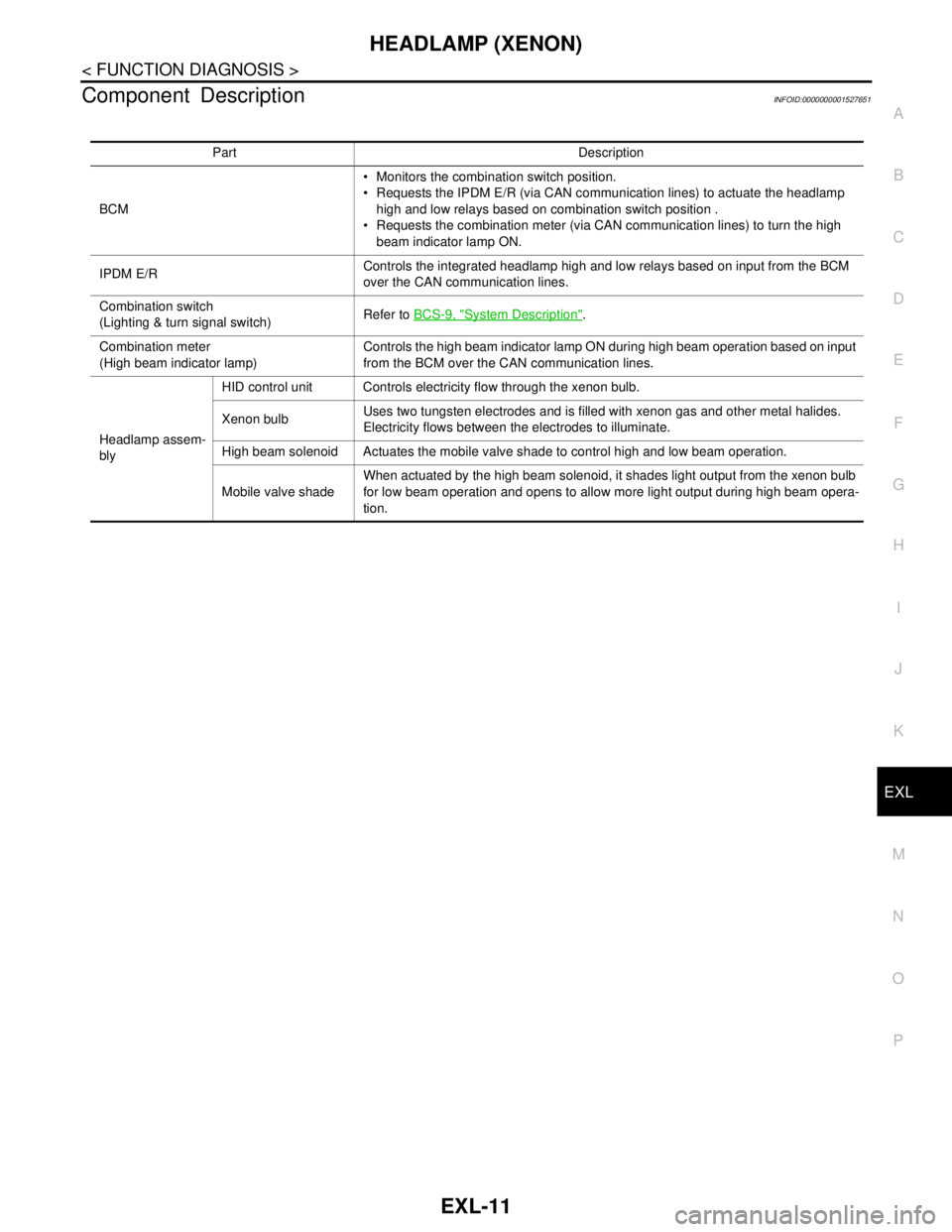
Component DescriptionINFOID:0000000001527651
Part Description
BCM• Monitors the combination switch position.
Requests the IPDM E/R (via CAN communication lines) to actuate the headlamp
high and low relays based on combination switch position .
Requests the combination meter (via CAN communication lines) to turn the high
beam indicator lamp ON.
IPDM E/RControls the integrated headlamp high and low relays based on input from the BCM
over the CAN communication lines.
Combination switch
(Lighting & turn signal switch)Refer to BCS-9, "
System Description".
Combination meter
(High beam indicator lamp)Controls the high beam indicator lamp ON during high beam operation based on input
from the BCM over the CAN communication lines.
Headlamp assem-
blyHID control unit Controls electricity flow through the xenon bulb.
Xenon bulbUses two tungsten electrodes and is filled with xenon gas and other metal halides.
Electricity flows between the electrodes to illuminate.
High beam solenoid Actuates the mobile valve shade to control high and low beam operation.
Mobile valve shadeWhen actuated by the high beam solenoid, it shades light output from the xenon bulb
for low beam operation and opens to allow more light output during high beam opera-
tion.
Page 3028 of 5883

DIAGNOSIS SYSTEM (BCM)
EXL-27
< FUNCTION DIAGNOSIS >
C
D
E
F
G
H
I
J
K
MA
B
EXL
N
O
P
ACTIVE TEST
FLASHER
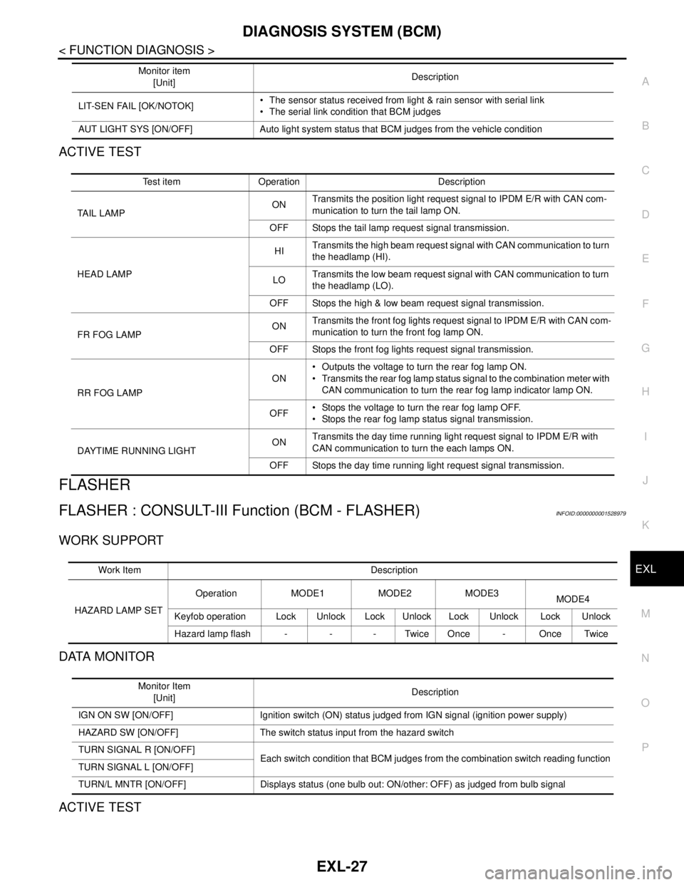
FLASHER : CONSULT-III Function (BCM - FLASHER)INFOID:0000000001528979
WORK SUPPORT
DATA MONITOR
ACTIVE TEST
LIT-SEN FAIL [OK/NOTOK] The sensor status received from light & rain sensor with serial link
The serial link condition that BCM judges
AUT LIGHT SYS [ON/OFF] Auto light system status that BCM judges from the vehicle conditionMonitor item
[Unit]Description
Test item Operation Description
TAIL LAMPONTransmits the position light request signal to IPDM E/R with CAN com-
munication to turn the tail lamp ON.
OFF Stops the tail lamp request signal transmission.
HEAD LAMPHITransmits the high beam request signal with CAN communication to turn
the headlamp (HI).
LOTransmits the low beam request signal with CAN communication to turn
the headlamp (LO).
OFF Stops the high & low beam request signal transmission.
FR FOG LAMPONTransmits the front fog lights request signal to IPDM E/R with CAN com-
munication to turn the front fog lamp ON.
OFF Stops the front fog lights request signal transmission.
RR FOG LAMPON Outputs the voltage to turn the rear fog lamp ON.
Transmits the rear fog lamp status signal to the combination meter with
CAN communication to turn the rear fog lamp indicator lamp ON.
OFF Stops the voltage to turn the rear fog lamp OFF.
Stops the rear fog lamp status signal transmission.
DAYTIME RUNNING LIGHTONTransmits the day time running light request signal to IPDM E/R with
CAN communication to turn the each lamps ON.
OFF Stops the day time running light request signal transmission.
Work Item Description
HAZARD LAMP SETOperation MODE1 MODE2 MODE3
MODE4
Keyfob operation Lock Unlock Lock Unlock Lock Unlock Lock Unlock
Hazard lamp flash - - - Twice Once - Once Twice
Monitor Item
[Unit]Description
IGN ON SW [ON/OFF] Ignition switch (ON) status judged from IGN signal (ignition power supply)
HAZARD SW [ON/OFF] The switch status input from the hazard switch
TURN SIGNAL R [ON/OFF]
Each switch condition that BCM judges from the combination switch reading function
TURN SIGNAL L [ON/OFF]
TURN/L MNTR [ON/OFF] Displays status (one bulb out: ON/other: OFF) as judged from bulb signal