2007 NISSAN TIIDA differential
[x] Cancel search: differentialPage 197 of 5883

NOISE, VIBRATION AND HARSHNESS (NVH) TROUBLESHOOTING
BR-5
< SYMPTOM DIAGNOSIS >
C
D
E
G
H
I
J
K
L
MA
B
BR
N
O
P
SYMPTOM DIAGNOSIS
NOISE, VIBRATION AND HARSHNESS (NVH) TROUBLESHOOTING
NVH Troubleshooting ChartINFOID:0000000001716910
Use the chart below to help you find the cause of the symptom. If necessary, repair or replace these parts.
×: ApplicableReference page
BR-10
, BR-28
BR-10
, BR-28BR-10
BR-10
, BR-11
BR-10
, BR-11
BR-10
, BR-11
BR-10
, BR-11
BR-11
, BR-10—
BR-34, BR-41
FAX-4, "
NVH Troubleshooting Chart
"
TM-623, "
NVH Troubleshooting Chart
",
TM-667, "
NVH Troubleshooting Chart
"
FSU-5, "
NVH Troubleshooting Chart
" (FSU),
RSU-2, "
NVH Troubleshooting Chart
" (RSU)
WT-4, "
NVH Troubleshooting Chart
"
WT-4, "
NVH Troubleshooting Chart
"
FAX-4, "
NVH Troubleshooting Chart
"
ST-5, "
NVH Troubleshooting Chart
"
Possible cause and
SUSPECTED PARTS
Pads damaged
Pads - uneven wear
Shims damaged
Rotor imbalance
Rotor damage
Rotor runout
Rotor deformation
Rotor deflection
Rotor rust
Rotor thickness variation
WHEEL HUB
DIFFERENTIAL
SUSPENSION
TIRES
ROAD WHEEL
DRIVE SHAFT
STEERING
SymptomNoise××× × × × ××××
Shake×××××××
Shimmy, Shudder××××××× × ×× ×
Page 2769 of 5883
![NISSAN TIIDA 2007 Service Repair Manual EM-122
< SERVICE DATA AND SPECIFICATIONS (SDS) [HR16DE]
SERVICE DATA AND SPECIFICATIONS (SDS)
SERVICE DATA AND SPECIFICATIONS (SDS)
SERVICE DATA AND SPECIFICATIONS (SDS)
General SpecificationINFOID:00 NISSAN TIIDA 2007 Service Repair Manual EM-122
< SERVICE DATA AND SPECIFICATIONS (SDS) [HR16DE]
SERVICE DATA AND SPECIFICATIONS (SDS)
SERVICE DATA AND SPECIFICATIONS (SDS)
SERVICE DATA AND SPECIFICATIONS (SDS)
General SpecificationINFOID:00](/manual-img/5/57395/w960_57395-2768.png)
EM-122
< SERVICE DATA AND SPECIFICATIONS (SDS) [HR16DE]
SERVICE DATA AND SPECIFICATIONS (SDS)
SERVICE DATA AND SPECIFICATIONS (SDS)
SERVICE DATA AND SPECIFICATIONS (SDS)
General SpecificationINFOID:0000000001381439
GENERAL SPECIFICATIONS
Drive BeltsINFOID:0000000001381440
BELT DEFLECTION:
*: When engine is cold.
BELT TENSION AND FREQUENCY:
Engine typeHR16DE
Cylinder arrangementIn-line 4
Displacement cm
3 (cu in)1,598 (97.51)
Bore and stroke mm (in)78.0 x 83.6 (3.071 x 3.291)
Valve arrangementDOHC
Firing order1-3-4-2
Number of piston ringsCompression 2
Oil 1
Number of main bearings5
Compression ratio10.7
Compression pressure
kPa (bar, kg/cm
2, psi)/200 rpmStandard 1,510 (15.1, 15.4, 219)
Minimum 1,265 (12.65, 12.9, 183)
Differential limit between cylinders 6.2 (0.06, 0.06, 0.9)
Valve timing
(Intake valve timing control - “ON”)
Unit: degree
abcde f
208 228 -11 (24) 59 (24) 4 24
JPBIA0552ZZ
LocationDeflection adjustment * Unit: mm (in)
Used belt
New belt
Limit After adjusted
Drive beltWith A/C models 7.9 (0.31) 4.8 - 5.3 (0.19 - 0.21) 4.2 - 4.5 (0.17 - 0.18)
Without A/C models 7.1 (0.28) 4.3 - 4.7 (0.17 - 0.19) 3.6 - 3.9 (0.14 - 0.15)
Applied pushing force 98 N (10 kg, 22 lb)
Page 2798 of 5883
![NISSAN TIIDA 2007 Service Repair Manual COMPRESSION PRESSURE
EM-151
< ON-VEHICLE MAINTENANCE >[MR18DE]
C
D
E
F
G
H
I
J
K
L
MA
EM
N
P O
COMPRESSION PRESSURE
Checking Compression PressureINFOID:0000000001346452
1. Warm up engine thoroughly. T NISSAN TIIDA 2007 Service Repair Manual COMPRESSION PRESSURE
EM-151
< ON-VEHICLE MAINTENANCE >[MR18DE]
C
D
E
F
G
H
I
J
K
L
MA
EM
N
P O
COMPRESSION PRESSURE
Checking Compression PressureINFOID:0000000001346452
1. Warm up engine thoroughly. T](/manual-img/5/57395/w960_57395-2797.png)
COMPRESSION PRESSURE
EM-151
< ON-VEHICLE MAINTENANCE >[MR18DE]
C
D
E
F
G
H
I
J
K
L
MA
EM
N
P O
COMPRESSION PRESSURE
Checking Compression PressureINFOID:0000000001346452
1. Warm up engine thoroughly. Then, stop it.
2. Release fuel pressure. Refer to EC-1035, "
Inspection".
3. Disconnect fuel pump fuse (1) to avoid fuel injection during mea-
surement.
4. Remove engine cover. Refer to EM-156, "
Component".
5. Remove ignition coil and spark plug from each cylinder. Refer to EM-145, "
Removal and Installation".
6. Connect an engine tachometer (not required in use of CONSULT-III).
7. Install a suitable compression tester with an adapter onto spark
plug hole.
Use the adapter whose picking up end inserted to spark plug
hole is smaller than 20 mm (0.79 in) in diameter. Otherwise, it
may be caught by cylinder head during removal.
8. With accelerator pedal fully depressed, turn ignition switch to “START” for cranking. When the gauge
pointer stabilizes, read the compression pressure and the engine rpm. Perform these steps to check each
cylinder.
Compression pressure:
Unit: kPa (bar, kg/cm2 psi) /rpm
CAUTION:
Always use a fully charged battery to obtain the specified engine speed.
If the engine speed is out of the specified range, check battery liquid for proper gravity. Check engine
speed again with normal battery gravity.
: Vehicle front
PBIA9861J
LBIA0459E
SBIA0533E
Standard Minimum Differential limit between cylinders
1,500 (15.0, 15.3, 217.6) / 200 1,200 (12.0, 12.2, 174) / 200 100 (1, 1, 15) / 200
Page 2885 of 5883
![NISSAN TIIDA 2007 Service Repair Manual EM-238
< SERVICE DATA AND SPECIFICATIONS (SDS) [MR18DE]
SERVICE DATA AND SPECIFICATIONS (SDS)
SERVICE DATA AND SPECIFICATIONS (SDS)
SERVICE DATA AND SPECIFICATIONS (SDS)
Standard and LimitINFOID:00000 NISSAN TIIDA 2007 Service Repair Manual EM-238
< SERVICE DATA AND SPECIFICATIONS (SDS) [MR18DE]
SERVICE DATA AND SPECIFICATIONS (SDS)
SERVICE DATA AND SPECIFICATIONS (SDS)
SERVICE DATA AND SPECIFICATIONS (SDS)
Standard and LimitINFOID:00000](/manual-img/5/57395/w960_57395-2884.png)
EM-238
< SERVICE DATA AND SPECIFICATIONS (SDS) [MR18DE]
SERVICE DATA AND SPECIFICATIONS (SDS)
SERVICE DATA AND SPECIFICATIONS (SDS)
SERVICE DATA AND SPECIFICATIONS (SDS)
Standard and LimitINFOID:0000000001337815
GENERAL SPECIFICATIONS
DRIVE BELT
WATER CONTROL VALVE
EXHAUST MANIFOLD
Unit: mm (in)
THERMOSTAT
SPARK PLUG
Unit: mm (in)
CYLINDER HEAD
Engine typeMR18DE
Cylinder arrangementIn-line 4
Displacement
cm
3 (cu in)1,798 (109.71)
Bore and stroke mm (in) 84.0 x 81.1 (3.307 x 3.192)
Valve arrangementDOHC
Firing order1-3-4-2
Number of piston ringsCompression 2
Oil 1
Compression ratio9.9
Compression pressure
kPa (bar, kg/cm
2 , psi) / 250 rpmStandard 1,500 (15.0, 15.3, 217.6)
Minimum 1,200 (12.0, 12.2, 174)
Differential limit between cylinders 100 (1.0, 1.0, 15)
Tension of drive belt Auto adjustment by auto-tensioner
Valve opening temperature 93.5 - 96.5°C (200 - 206°F)
Maximum valve lift 8 mm/ 108°C (0.315 in/ 226°F)
Valve closing temperature More than 90°C (194°F)
Items Limit
Surface distortionEach exhaust port 0.3 (0.012)
Entire part 0.7 (0.028)
Valve opening temperature 80.5 - 83.5°C (177 - 182°F)
Maximum valve lift 8 mm/ 95°C (0.315 in/ 203°F)
Valve closing temperature More than 77°C (171°F)
Plug typePlatinum-tipped TYPE
MakeNGK
Standard typePLZKAR6A-11
Spark plug gapNominal: 1.1 (0.043)
Page 3137 of 5883

PREPARATION
FAX-3
< PREPARATION >
C
E
F
G
H
I
J
K
L
MA
B
FA X
N
O
P
PREPARATION
PREPARATION
Special Service ToolINFOID:0000000001716782
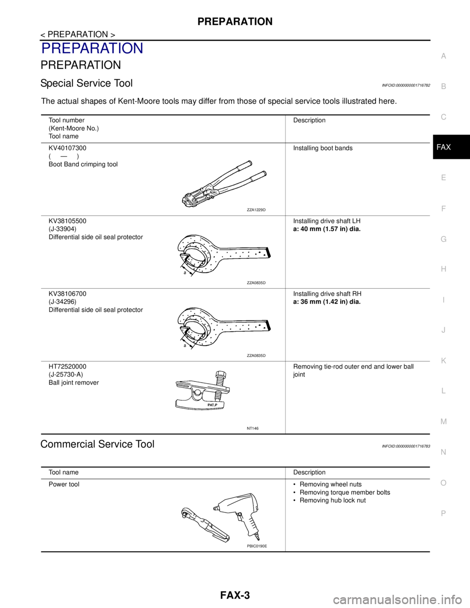
The actual shapes of Kent-Moore tools may differ from those of special service tools illustrated here.
Commercial Service ToolINFOID:0000000001716783
Tool number
(Kent-Moore No.)
Tool nameDescription
KV40107300
(—)
Boot Band crimping toolInstalling boot bands
KV38105500
(J-33904)
Differential side oil seal protectorInstalling drive shaft LH
a: 40 mm (1.57 in) dia.
KV38106700
(J-34296)
Differential side oil seal protectorInstalling drive shaft RH
a: 36 mm (1.42 in) dia.
HT72520000
(J-25730-A)
Ball joint removerRemoving tie-rod outer end and lower ball
joint
ZZA1229D
ZZA0835D
ZZA0835D
NT146
Tool nameDescription
Power tool Removing wheel nuts
Removing torque member bolts
Removing hub lock nut
PBIC0190E
Page 3145 of 5883

FRONT DRIVE SHAFT
FAX-11
< REMOVAL AND INSTALLATION >
C
E
F
G
H
I
J
K
L
MA
B
FA X
N
O
P
Check boot for cracks or other damage, and for grease leakage.
If damaged, disassemble drive shaft to verify damage, and repair
or replace as necessary.
INSTALLATION
Installation is in the reverse order of removal.
CAUTION:
Do not reuse non-reusable parts.
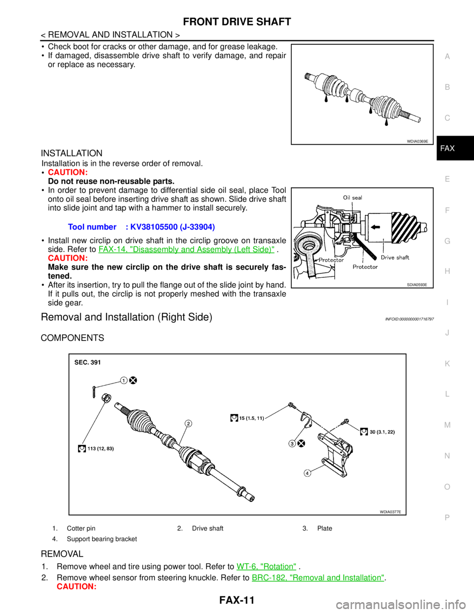
In order to prevent damage to differential side oil seal, place Tool
onto oil seal before inserting drive shaft as shown. Slide drive shaft
into slide joint and tap with a hammer to install securely.
Install new circlip on drive shaft in the circlip groove on transaxle
side. Refer to FAX-14, "
Disassembly and Assembly (Left Side)" .
CAUTION:
Make sure the new circlip on the drive shaft is securely fas-
tened.
After its insertion, try to pull the flange out of the slide joint by hand.
If it pulls out, the circlip is not properly meshed with the transaxle
side gear.
Removal and Installation (Right Side)INFOID:0000000001716797
COMPONENTS
REMOVAL
1. Remove wheel and tire using power tool. Refer to WT-6, "Rotation" .
2. Remove wheel sensor from steering knuckle. Refer to BRC-182, "
Removal and Installation".
CAUTION:
WDIA0369E
Tool number : KV38105500 (J-33904)
SDIA0593E
1. Cotter pin 2. Drive shaft 3. Plate
4. Support bearing bracket
WDIA0377E
Page 3146 of 5883

FAX-12
< REMOVAL AND INSTALLATION >
FRONT DRIVE SHAFT
Do not pull on wheel sensor harness.
3. Remove transverse link ball joint nut and bolt. Then, remove transverse link from steering knuckle.
4. Remove cotter pin, then loosen hub lock nut using power tool.
CAUTION:
Temporarily leave the hub lock nut installed to prevent damage to threads.
5. Separate the drive shaft from the wheel hub and bearing assem-
bly by lightly tapping the end of the drive shaft using a hammer
or suitable tool and wood block, and then remove hub lock nut.
NOTE:
Use a suitable puller if wheel hub and bearing assembly and
drive shaft cannot be separated after performing the above pro-
cedure.
6. Remove the drive shaft from the wheel hub and bearing assem-
bly.
CAUTION:
Do not apply an excessive angle to drive shaft joint when
removing from the wheel hub and bearing assembly,
Do not excessively extend slide joint.
Do not allow drive shaft to hang down. Support the entire drive shaft.
7. Remove the plate bolts and plate.
8. Remove the drive shaft from the transaxle assembly.
CAUTION:
Do not apply an excessive angle to drive shaft joint when removing from the transaxle.
Do not excessively extend slide joint.
Do not allow drive shaft to hang down. Support the entire drive shaft.
9. If necessary, remove the support bearing bracket bolts and the support bearing bracket.
INSPECTION AFTER REMOVAL
Move joint up/down, left/right, and in axial direction. Check for any rough movement or significant looseness.
Check boot for cracks or other damage, and for grease leakage.
If damaged, disassemble drive shaft to verify damage, and repair
or replace as necessary.
Check for cracks or other damage to the support bearing bracket,
replace as necessary.
INSTALLATION
Installation is in the reverse order of removal. Note the following:
Refer to "COMPONENTS" for tightening torque.
CAUTION:
Do not reuse non-reusable parts.
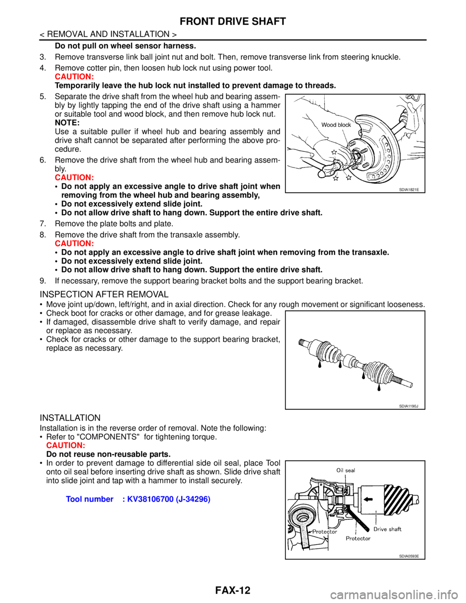
In order to prevent damage to differential side oil seal, place Tool
onto oil seal before inserting drive shaft as shown. Slide drive shaft
into slide joint and tap with a hammer to install securely.
SDIA1821E
SDIA1190J
Tool number : KV38106700 (J-34296)
SDIA0593E
Page 3223 of 5883

TERMINOLOGY
GI-29
< HOW TO USE THIS MANUAL >
C
D
E
F
G
H
I
J
K
L
MB
GI
N
O
P
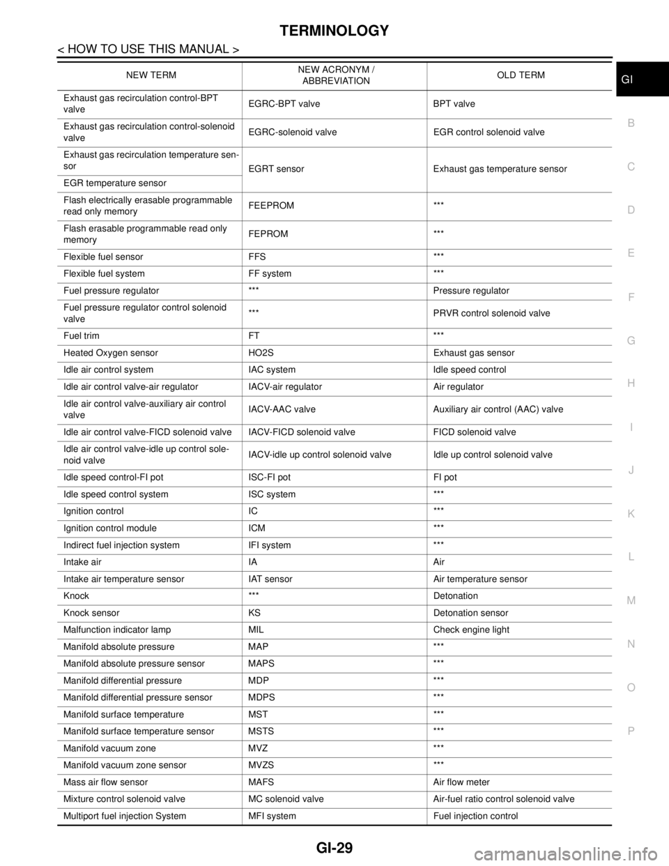
Exhaust gas recirculation control-BPT
valveEGRC-BPT valve BPT valve
Exhaust gas recirculation control-solenoid
valveEGRC-solenoid valve EGR control solenoid valve
Exhaust gas recirculation temperature sen-
sor
EGRT sensor Exhaust gas temperature sensor
EGR temperature sensor
Flash electrically erasable programmable
read only memoryFEEPROM ***
Flash erasable programmable read only
memoryFEPROM ***
Flexible fuel sensor FFS ***
Flexible fuel system FF system ***
Fuel pressure regulator *** Pressure regulator
Fuel pressure regulator control solenoid
valve*** PRVR control solenoid valve
Fuel trim FT ***
Heated Oxygen sensor HO2S Exhaust gas sensor
Idle air control system IAC system Idle speed control
Idle air control valve-air regulator IACV-air regulator Air regulator
Idle air control valve-auxiliary air control
valveIACV-AAC valve Auxiliary air control (AAC) valve
Idle air control valve-FICD solenoid valve IACV-FICD solenoid valve FICD solenoid valve
Idle air control valve-idle up control sole-
noid valveIACV-idle up control solenoid valve Idle up control solenoid valve
Idle speed control-FI pot ISC-FI pot FI pot
Idle speed control system ISC system ***
Ignition control IC ***
Ignition control module ICM ***
Indirect fuel injection system IFI system ***
Intake air IA Air
Intake air temperature sensor IAT sensor Air temperature sensor
Knock *** Detonation
Knock sensor KS Detonation sensor
Malfunction indicator lamp MIL Check engine light
Manifold absolute pressure MAP ***
Manifold absolute pressure sensor MAPS ***
Manifold differential pressure MDP ***
Manifold differential pressure sensor MDPS ***
Manifold surface temperature MST ***
Manifold surface temperature sensor MSTS ***
Manifold vacuum zone MVZ ***
Manifold vacuum zone sensor MVZS ***
Mass air flow sensor MAFS Air flow meter
Mixture control solenoid valve MC solenoid valve Air-fuel ratio control solenoid valve
Multiport fuel injection System MFI system Fuel injection controlNEW TERMNEW ACRONYM /
ABBREVIATIONOLD TERM