2007 NISSAN TIIDA body interior
[x] Cancel search: body interiorPage 3716 of 5883

IP-1
BODY INTERIOR
C
D
E
F
G
H
I
K
L
M
SECTION IP
A
B
IP
N
O
P
CONTENTS
INSTRUMENT PANEL
SERVICE INFORMATION ............................2
PRECAUTIONS ...................................................2
Precaution for Supplemental Restraint System
(SRS) "AIR BAG" and "SEAT BELT PRE-TEN-
SIONER" ...................................................................
2
Precaution .................................................................2
PREPARATION ...................................................3
Commercial Service Tool ..........................................3
SQUEAK AND RATTLE TROUBLE DIAG-
NOSES ...............................................................
4
Work Flow .................................................................4
Generic Squeak and Rattle Troubleshooting ............6
Diagnostic Worksheet ...............................................8
INSTRUMENT PANEL ASSEMBLY .................10
Component Parts .....................................................10
Removal and Installation .........................................11
Disassembly and Assembly .....................................23
Page 4370 of 5883

MWI
BCM (BODY CONTROL MODULE)
MWI-63
< ECU DIAGNOSIS >
C
D
E
F
G
H
I
J
K
L
MB A
O
P
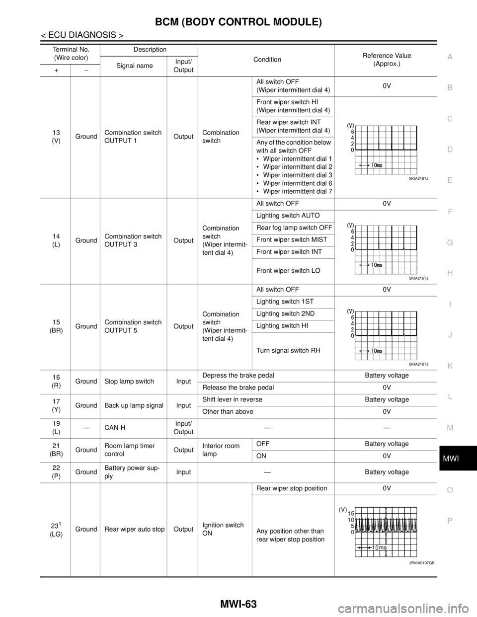
13
(V)GroundCombination switch
OUTPUT 1OutputCombination
switchAll switch OFF
(Wiper intermittent dial 4)0V
Front wiper switch HI
(Wiper intermittent dial 4)
Rear wiper switch INT
(Wiper intermittent dial 4)
Any of the condition below
with all switch OFF
Wiper intermittent dial 1
Wiper intermittent dial 2
Wiper intermittent dial 3
Wiper intermittent dial 6
Wiper intermittent dial 7
14
(L)GroundCombination switch
OUTPUT 3OutputCombination
switch
(Wiper intermit-
tent dial 4)All switch OFF 0V
Lighting switch AUTO
Rear fog lamp switch OFF
Front wiper switch MIST
Front wiper switch INT
Front wiper switch LO
15
(BR)GroundCombination switch
OUTPUT 5OutputCombination
switch
(Wiper intermit-
tent dial 4)All switch OFF 0V
Lighting switch 1ST
Lighting switch 2ND
Lighting switch HI
Turn signal switch RH
16
(R)Ground Stop lamp switch InputDepress the brake pedal Battery voltage
Release the brake pedal 0V
17
(Y)Ground Back up lamp signal InputShift lever in reverse Battery voltage
Other than above 0V
19
(L)—CAN-HInput/
Output——
21
(BR)GroundRoom lamp timer
controlOutputInterior room
lampOFF Battery voltage
ON 0V
22
(P)GroundBattery power sup-
plyInput — Battery voltage
23
1
(LG)Ground Rear wiper auto stop OutputIgnition switch
ONRear wiper stop position 0V
Any position other than
rear wiper stop position Terminal No.
(Wire color)Description
ConditionReference Value
(Approx.)
Signal nameInput/
Output +−
SKIA2167J
SKIA2167J
SKIA2167J
JPMIA0197GB
Page 4376 of 5883

MWI
BCM (BODY CONTROL MODULE)
MWI-69
< ECU DIAGNOSIS >
C
D
E
F
G
H
I
J
K
L
MB A
O
P
1: Hatchback
2: Sedan
3: Manual A/C
4: Superlock
5: Remote keyless entry
6: Intelligent Key
7: LHD diesel69
(G)Ground Rear fog lamp OutputLighting switch
1ST and front
fog lamp switch
ONRear fog lamp switch OFF 0V
Rear fog lamp switch ON Battery voltage
70
(B)Ground Ground — — 0V
71
1
(V)Ground Rear wiper motor OutputRear wiper switch OFF 0V
Rear wiper switch ON Battery voltage
72
(LG)GroundBattery power sup-
plyInput — Battery voltage
73
(R)GroundInterior room lamp
power supplyOutputAfter passing the interior room lamp battery
saver operation time0V
Any other time after passing the interior room
lamp battery saver operation timeBattery voltage
74
(Y)GroundBattery power sup-
plyInput — Battery voltage
75
4
(V)Ground Super lock OutputWhen lock button of keyfob or Intelligent Key
is not pressed 0V
When lock button of keyfob or Intelligent Key
is pressed Battery voltage
76
(G)Ground Driver door unlock OutputDoor lock/un-
lock switchPressed to the unlock side Battery voltage
Pressed to the lock side 0V
77
(SB)Ground Door lock (All) OutputDoor lock/un-
lock switchPressed to the unlock side 0V
Pressed to the lock side Battery voltage
78
(L)GroundPower window pow-
er supplyOutput Ignition switchOFF or ACC 0V
ON Battery voltage
79
(Y)GroundBattery power sup-
plyInput — Battery voltage Terminal No.
(Wire color)Description
ConditionReference Value
(Approx.)
Signal nameInput/
Output +−
Page 4597 of 5883

SE-1
BODY INTERIOR
C
D
E
F
G
H
I
K
L
M
SECTION SE
A
B
SE
N
O
P
CONTENTS
SEAT
COMPONENT DIAGNOSIS ..........................2
HEATED SEAT ....................................................2
Wiring Diagram .........................................................2
SYMPTOM DIAGNOSIS ...............................5
SQUEAK AND RATTLE TROUBLE DIAG-
NOSES ................................................................
5
Work Flow .................................................................5
Generic Squeak and Rattle Troubleshooting ............7
Diagnostic Worksheet ...............................................9
PRECAUTION ..............................................11
PRECAUTIONS ..................................................11
Precaution for Supplemental Restraint System
(SRS) "AIR BAG" and "SEAT BELT PRE-TEN-
SIONER" .................................................................
11
PREPARATION ...........................................12
PREPARATION ..................................................12
Special Service Tool ...............................................12
Commercial Service Tool ........................................12
REMOVAL AND INSTALLATION ...............13
FRONT SEAT ....................................................13
Exploded View .........................................................13
Removal and Installation .........................................14
REAR SEAT ......................................................16
Exploded View .........................................................16
Removal and Installation .........................................18
Removal and Installation .........................................20
ON-VEHICLE REPAIR .................................21
FRONT SEAT ....................................................21
Exploded View .........................................................21
Disassembly and Assembly .....................................22
REAR SEAT ......................................................24
Exploded View .........................................................24
Disassembly and Assembly .....................................26
Disassembly and Assembly .....................................27
Page 5779 of 5883

WCS-64
< ECU DIAGNOSIS >
BCM (BODY CONTROL MODULE)
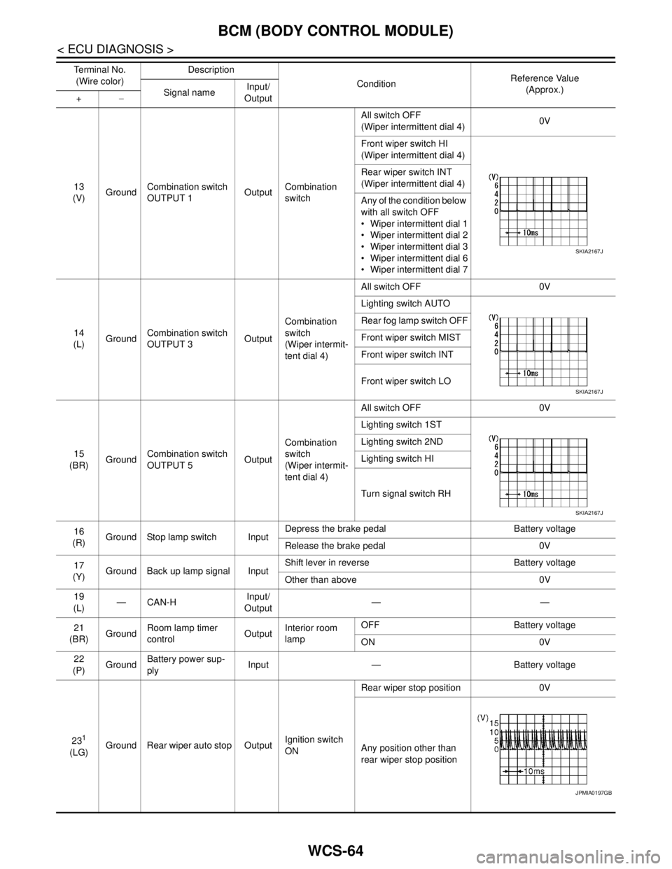
13
(V)GroundCombination switch
OUTPUT 1OutputCombination
switchAll switch OFF
(Wiper intermittent dial 4)0V
Front wiper switch HI
(Wiper intermittent dial 4)
Rear wiper switch INT
(Wiper intermittent dial 4)
Any of the condition below
with all switch OFF
Wiper intermittent dial 1
Wiper intermittent dial 2
Wiper intermittent dial 3
Wiper intermittent dial 6
Wiper intermittent dial 7
14
(L)GroundCombination switch
OUTPUT 3OutputCombination
switch
(Wiper intermit-
tent dial 4)All switch OFF 0V
Lighting switch AUTO
Rear fog lamp switch OFF
Front wiper switch MIST
Front wiper switch INT
Front wiper switch LO
15
(BR)GroundCombination switch
OUTPUT 5OutputCombination
switch
(Wiper intermit-
tent dial 4)All switch OFF 0V
Lighting switch 1ST
Lighting switch 2ND
Lighting switch HI
Turn signal switch RH
16
(R)Ground Stop lamp switch InputDepress the brake pedal Battery voltage
Release the brake pedal 0V
17
(Y)Ground Back up lamp signal InputShift lever in reverse Battery voltage
Other than above 0V
19
(L)—CAN-HInput/
Output——
21
(BR)GroundRoom lamp timer
controlOutputInterior room
lampOFF Battery voltage
ON 0V
22
(P)GroundBattery power sup-
plyInput — Battery voltage
23
1
(LG)Ground Rear wiper auto stop OutputIgnition switch
ONRear wiper stop position 0V
Any position other than
rear wiper stop position Te r m i n a l N o .
(Wire color)Description
ConditionReference Value
(Approx.)
Signal nameInput/
Output +−
SKIA2167J
SKIA2167J
SKIA2167J
JPMIA0197GB
Page 5785 of 5883

WCS-70
< ECU DIAGNOSIS >
BCM (BODY CONTROL MODULE)
1: Hatchback
2: Sedan
3: Manual A/C
4: Superlock
5: Remote keyless entry
6: Intelligent Key
7: LHD diesel69
(G)Ground Rear fog lamp OutputLighting switch
1ST and front
fog lamp switch
ONRear fog lamp switch OFF 0V
Rear fog lamp switch ON Battery voltage
70
(B)Ground Ground — — 0V
71
1
(V)Ground Rear wiper motor OutputRear wiper switch OFF 0V
Rear wiper switch ON Battery voltage
72
(LG)GroundBattery power sup-
plyInput — Battery voltage
73
(R)GroundInterior room lamp
power supplyOutputAfter passing the interior room lamp battery
saver operation time0V
Any other time after passing the interior room
lamp battery saver operation timeBattery voltage
74
(Y)GroundBattery power sup-
plyInput — Battery voltage
75
4
(V)Ground Super lock OutputWhen lock button of keyfob or Intelligent Key
is not pressed 0V
When lock button of keyfob or Intelligent Key
is pressed Battery voltage
76
(G)Ground Driver door unlock OutputDoor lock/un-
lock switchPressed to the unlock side Battery voltage
Pressed to the lock side 0V
77
(SB)Ground Door lock (All) OutputDoor lock/un-
lock switchPressed to the unlock side 0V
Pressed to the lock side Battery voltage
78
(L)GroundPower window pow-
er supplyOutput Ignition switchOFF or ACC 0V
ON Battery voltage
79
(Y)GroundBattery power sup-
plyInput — Battery voltage Te r m i n a l N o .
(Wire color)Description
ConditionReference Value
(Approx.)
Signal nameInput/
Output +−