2007 NISSAN TIIDA ABS
[x] Cancel search: ABSPage 5445 of 5883
![NISSAN TIIDA 2007 Service Repair Manual KEY INTERLOCK CABLE
TM-499
< ON-VEHICLE REPAIR >[TYPE 2 (4AT: RE4F03B)]
C
E
F
G
H
I
J
K
L
MA
B
TM
N
O
P
KEY INTERLOCK CABLE
Removal and InstallationINFOID:0000000001731426
COMPONENTS
REMOVAL
CAUTION:
NISSAN TIIDA 2007 Service Repair Manual KEY INTERLOCK CABLE
TM-499
< ON-VEHICLE REPAIR >[TYPE 2 (4AT: RE4F03B)]
C
E
F
G
H
I
J
K
L
MA
B
TM
N
O
P
KEY INTERLOCK CABLE
Removal and InstallationINFOID:0000000001731426
COMPONENTS
REMOVAL
CAUTION:](/manual-img/5/57395/w960_57395-5444.png)
KEY INTERLOCK CABLE
TM-499
< ON-VEHICLE REPAIR >[TYPE 2 (4AT: RE4F03B)]
C
E
F
G
H
I
J
K
L
MA
B
TM
N
O
P
KEY INTERLOCK CABLE
Removal and InstallationINFOID:0000000001731426
COMPONENTS
REMOVAL
CAUTION:
Make sure that parking brake is applied before removal and installation.
1. Place the selector lever in the “N” position.
2. Remove the selector lever knob. Refer to TM-496, "
Selector Lever Knob Removal and Installation".
3. Remove the center console assembly. Refer to IP-11, "
Removal and Installation".
4. Slide the slider (A) toward the casing cap (B) while pressing tabs
(C) on the slider to separate the slider (A) from the adjust holder
(D).
5. Remove the casing cap (B) from the cable bracket on the control
device assembly.
6. Remove the key interlock cable from the key interlock rod (E).
1. Key interlock cable 2. Key cylinder 3. Control device assembly
A. Lock plate B. Holder C. Clip
D. Slider E. Key interlock rod F. Adjust holder
G. C a s i n g c a p
WCIA0621E
SCIA6975E
Page 5447 of 5883
![NISSAN TIIDA 2007 Service Repair Manual KEY INTERLOCK CABLE
TM-501
< ON-VEHICLE REPAIR >[TYPE 2 (4AT: RE4F03B)]
C
E
F
G
H
I
J
K
L
MA
B
TM
N
O
P
8. Slide the slider (A) toward the key interlock rod (D) while press-
ing the pull lock (B) down NISSAN TIIDA 2007 Service Repair Manual KEY INTERLOCK CABLE
TM-501
< ON-VEHICLE REPAIR >[TYPE 2 (4AT: RE4F03B)]
C
E
F
G
H
I
J
K
L
MA
B
TM
N
O
P
8. Slide the slider (A) toward the key interlock rod (D) while press-
ing the pull lock (B) down](/manual-img/5/57395/w960_57395-5446.png)
KEY INTERLOCK CABLE
TM-501
< ON-VEHICLE REPAIR >[TYPE 2 (4AT: RE4F03B)]
C
E
F
G
H
I
J
K
L
MA
B
TM
N
O
P
8. Slide the slider (A) toward the key interlock rod (D) while press-
ing the pull lock (B) down to securely connect the adjust holder
(C) with the key interlock rod (D).
CAUTION:
Do not press tabs when holding slider (A).
Do not apply any side to side force to key interlock rod (D)
when sliding slider (A).
9. Secure the key interlock cable (1) with the clip (A).
10. Install steering column cover (upper and lower) and instrument
lower finisher. Refer to IP-11, "
Removal and Installation".
11. Install the center console assembly. Refer to IP-11, "
Removal
and Installation".
12. Install the selector lever knob. Refer to TM-496, "
Selector Lever
Knob Removal and Installation".
13. Check shift lock system. Refer to TM-31, "
System Description".
SCIA6978E
SCIA6973E
Page 5664 of 5883
![NISSAN TIIDA 2007 Service Repair Manual PRECAUTIONS
VTL-3
< PRECAUTION >[AUTOMATIC AIR CONDITIONER]
C
D
E
F
G
H
J
K
L
MA
B
VTL
N
O
P
PRECAUTION
PRECAUTIONS
Precaution for Supplemental Restraint System (SRS) "AIR BAG" and "SEAT BELT
PRE-TEN NISSAN TIIDA 2007 Service Repair Manual PRECAUTIONS
VTL-3
< PRECAUTION >[AUTOMATIC AIR CONDITIONER]
C
D
E
F
G
H
J
K
L
MA
B
VTL
N
O
P
PRECAUTION
PRECAUTIONS
Precaution for Supplemental Restraint System (SRS) "AIR BAG" and "SEAT BELT
PRE-TEN](/manual-img/5/57395/w960_57395-5663.png)
PRECAUTIONS
VTL-3
< PRECAUTION >[AUTOMATIC AIR CONDITIONER]
C
D
E
F
G
H
J
K
L
MA
B
VTL
N
O
P
PRECAUTION
PRECAUTIONS
Precaution for Supplemental Restraint System (SRS) "AIR BAG" and "SEAT BELT
PRE-TENSIONER"
INFOID:0000000001696273
The Supplemental Restraint System such as “AIR BAG” and “SEAT BELT PRE-TENSIONER”, used along
with a front seat belt, helps to reduce the risk or severity of injury to the driver and front passenger for certain
types of collision. Information necessary to service the system safely is included in the SR and SB section of
this Service Manual.
WARNING:
• To avoid rendering the SRS inoperative, which could increase the risk of personal injury or death in
the event of a collision which would result in air bag inflation, all maintenance must be performed by
an authorized NISSAN/INFINITI dealer.
Improper maintenance, including incorrect removal and installation of the SRS, can lead to personal
injury caused by unintentional activation of the system. For removal of Spiral Cable and Air Bag
Module, see the SR section.
Do not use electrical test equipment on any circuit related to the SRS unless instructed to in this
Service Manual. SRS wiring harnesses can be identified by yellow and/or orange harnesses or har-
ness connectors.
Precaution for Working with HFC-134a (R-134a)INFOID:0000000001696274
WARNING:
Use only specified oil for the HFC-134a (R-134a) A/C system and HFC-134a (R-134a) components. If
oil other than that specified is used, compressor malfunction is likely to occur.
The specified HFC-134a (R-134a) oil rapidly absorbs moisture from the atmosphere. The following
handling precautions must be observed:
- When removing refrigerant components from a vehicle, immediately cap (seal) the component to
minimize the entry of moisture from the atmosphere.
- When installing refrigerant components to a vehicle, do not remove the caps (unseal) until just
before connecting the components. Connect all refrigerant loop components as quickly as possible
to minimize the entry of moisture into system.
- Only use the specified oil from a sealed container. Immediately reseal containers of oil. Without
proper sealing, oil will become moisture saturated and should not be used.
- Avoid breathing A/C refrigerant and oil vapor or mist. Exposure may irritate eyes, nose and throat.
Use only approved recovery/recycling equipment to discharge HFC-134a (R-134a) refrigerant. If acci-
dental system discharge occurs, ventilate work area before resuming service. Additional health and
safety information may be obtained from refrigerant and oil manufacturers.
- Do not allow A/C oil to come in contact with styrofoam parts. Damage may result.
Page 5691 of 5883
![NISSAN TIIDA 2007 Service Repair Manual VTL-30
< PRECAUTION >[MANUAL AIR CONDITIONER]
PRECAUTIONS
PRECAUTION
PRECAUTIONS
Precaution for Supplemental Restraint System (SRS) "AIR BAG" and "SEAT BELT
PRE-TENSIONER"
INFOID:0000000001696378
The NISSAN TIIDA 2007 Service Repair Manual VTL-30
< PRECAUTION >[MANUAL AIR CONDITIONER]
PRECAUTIONS
PRECAUTION
PRECAUTIONS
Precaution for Supplemental Restraint System (SRS) "AIR BAG" and "SEAT BELT
PRE-TENSIONER"
INFOID:0000000001696378
The](/manual-img/5/57395/w960_57395-5690.png)
VTL-30
< PRECAUTION >[MANUAL AIR CONDITIONER]
PRECAUTIONS
PRECAUTION
PRECAUTIONS
Precaution for Supplemental Restraint System (SRS) "AIR BAG" and "SEAT BELT
PRE-TENSIONER"
INFOID:0000000001696378
The Supplemental Restraint System such as “AIR BAG” and “SEAT BELT PRE-TENSIONER”, used along
with a front seat belt, helps to reduce the risk or severity of injury to the driver and front passenger for certain
types of collision. Information necessary to service the system safely is included in the SR and SB section of
this Service Manual.
WARNING:
To avoid rendering the SRS inoperative, which could increase the risk of personal injury or death in
the event of a collision which would result in air bag inflation, all maintenance must be performed by
an authorized NISSAN/INFINITI dealer.
Improper maintenance, including incorrect removal and installation of the SRS, can lead to personal
injury caused by unintentional activation of the system. For removal of Spiral Cable and Air Bag
Module, see the SR section.
Do not use electrical test equipment on any circuit related to the SRS unless instructed to in this
Service Manual. SRS wiring harnesses can be identified by yellow and/or orange harnesses or har-
ness connectors.
Precaution for Working with HFC-134a (R-134a)INFOID:0000000001696379
WARNING:
Use only specified oil for the HFC-134a (R-134a) A/C system and HFC-134a (R-134a) components. If
oil other than that specified is used, compressor malfunction is likely to occur.
The specified HFC-134a (R-134a) oil rapidly absorbs moisture from the atmosphere. The following
handling precautions must be observed:
- When removing refrigerant components from a vehicle, immediately cap (seal) the component to
minimize the entry of moisture from the atmosphere.
- When installing refrigerant components to a vehicle, do not remove the caps (unseal) until just
before connecting the components. Connect all refrigerant loop components as quickly as possible
to minimize the entry of moisture into system.
- Only use the specified oil from a sealed container. Immediately reseal containers of oil. Without
proper sealing, oil will become moisture saturated and should not be used.
- Avoid breathing A/C refrigerant and oil vapor or mist. Exposure may irritate eyes, nose and throat.
Use only approved recovery/recycling equipment to discharge HFC-134a (R-134a) refrigerant. If acci-
dental system discharge occurs, ventilate work area before resuming service. Additional health and
safety information may be obtained from refrigerant and oil manufacturers.
- Do not allow A/C oil to come in contact with styrofoam parts. Damage may result.
Page 5696 of 5883
![NISSAN TIIDA 2007 Service Repair Manual CONTROLLER
VTL-35
< ON-VEHICLE REPAIR >[MANUAL AIR CONDITIONER]
C
D
E
F
G
H
J
K
L
MA
B
VTL
N
O
P
Disassembly and AssemblyINFOID:0000000001696529
CAUTION:
Install inner cable of each door cable to the NISSAN TIIDA 2007 Service Repair Manual CONTROLLER
VTL-35
< ON-VEHICLE REPAIR >[MANUAL AIR CONDITIONER]
C
D
E
F
G
H
J
K
L
MA
B
VTL
N
O
P
Disassembly and AssemblyINFOID:0000000001696529
CAUTION:
Install inner cable of each door cable to the](/manual-img/5/57395/w960_57395-5695.png)
CONTROLLER
VTL-35
< ON-VEHICLE REPAIR >[MANUAL AIR CONDITIONER]
C
D
E
F
G
H
J
K
L
MA
B
VTL
N
O
P
Disassembly and AssemblyINFOID:0000000001696529
CAUTION:
Install inner cable of each door cable to the corresponding
lever, as shown in the figure. Press outer cable until it hooks on
the tabs and becomes secure.
1. Air mix door cable 2. Intake door cable 3. Mode door cable
4. A/C controller assembly 5. Mode control dial 6. Rear DEF button
7. A/C button 8. Temperature control dial 9. Illumination bulb
10. Intake door lever knob 11. Fan control dial
ZJIA0106J
MJIA0038E
Page 5721 of 5883

WCS-6
< FUNCTION DIAGNOSIS >
WARNING CHIME SYSTEM
WARNING CHIME SYSTEM : Component Description
INFOID:0000000001722907
LIGHT REMINDER WARNING CHIME
LIGHT REMINDER WARNING CHIME : System DiagramINFOID:0000000001722908
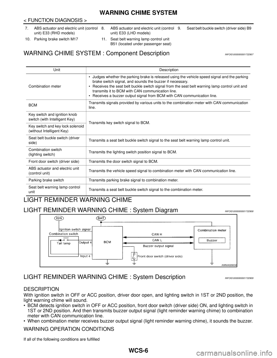
LIGHT REMINDER WARNING CHIME : System DescriptionINFOID:0000000001722909
DESCRIPTION
With ignition switch in OFF or ACC position, driver door open, and lighting switch in 1ST or 2ND position, the
light warning chime will sound.
BCM detects ignition switch in OFF or ACC position, front door switch (driver side) ON, and lighting switch in
1ST or 2ND position. And then transmits buzzer output signal (light reminder warning chime) to combination
meter with CAN communication line.
When combination meter receives buzzer output signal (light reminder warning chime), it sounds the buzzer.
WARNING OPERATION CONDITIONS
If all of the following conditions are fulfilled
7. ABS actuator and electric unit (control
unit) E33 (RHD models)8. ABS actuator and electric unit (control
unit) E33 (LHD models)9. Seat belt buckle switch (driver side) B9
10. Parking brake switch M17 11. Seat belt warning lamp control unit
B51 (located under passenger seat)
Unit Description
Combination meter Judges whether the parking brake is released using the vehicle speed signal and the parking
brake switch signal, and sounds the buzzer if necessary.
Receives the seat belt buckle switch signal from the seat belt warning lamp control unit and
transmits it to BCM with CAN communication line.
Receives a buzzer output signal from BCM with CAN communication line.
BCMTransmits signals provided by various units to the combination meter with CAN communication
line.
Key switch and ignition knob
switch (with Intelligent Key)
Transmits key switch signal to BCM.
Key switch and key lock solenoid
(without Intelligent Key)
Seat belt buckle switch (driver
side)Transmits a seat belt buckle switch signal to the seat belt warning lamp control unit.
Combination switch
(lighting switch)Transmits the lighting switch position signal to BCM.
Front door switch (driver side) Transmits the door switch signal to BCM.
ABS actuator and electric unit
(control unit)Transmits the vehicle speed signal to combination meter with CAN communication line.
Parking brake switch Transmits parking brake signal to combination meter.
Seat belt warning lamp control
unitTransmits a seat belt buckle switch signal to the combination meter.
AWNIA0260GB
Page 5724 of 5883

WCS
WARNING CHIME SYSTEM
WCS-9
< FUNCTION DIAGNOSIS >
C
D
E
F
G
H
I
J
K
L
MB A
O
P
LIGHT REMINDER WARNING CHIME : Component DescriptionINFOID:0000000001722911
SEAT BELT WARNING CHIME
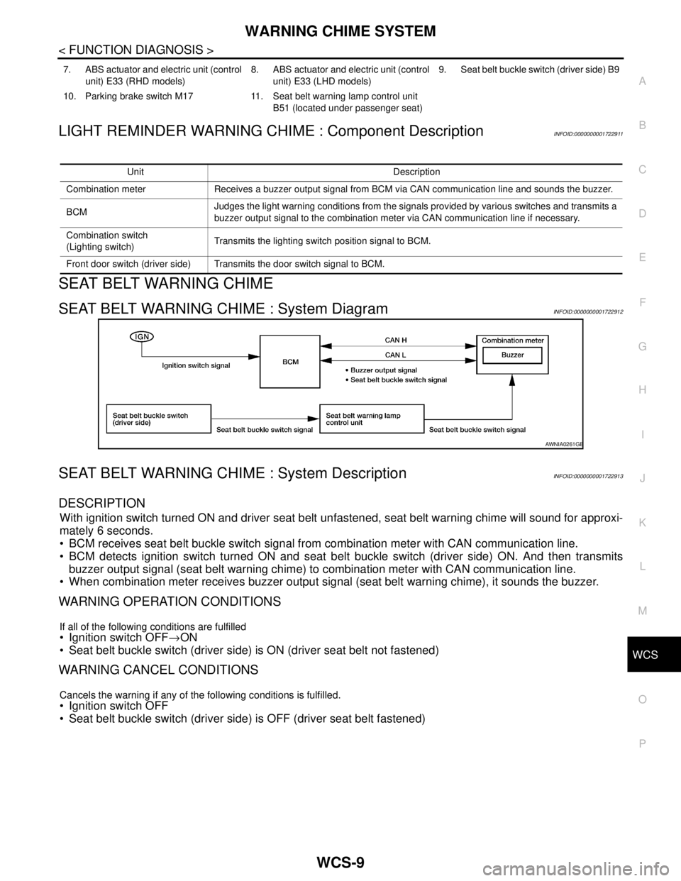
SEAT BELT WARNING CHIME : System DiagramINFOID:0000000001722912
SEAT BELT WARNING CHIME : System DescriptionINFOID:0000000001722913
DESCRIPTION
With ignition switch turned ON and driver seat belt unfastened, seat belt warning chime will sound for approxi-
mately 6 seconds.
BCM receives seat belt buckle switch signal from combination meter with CAN communication line.
BCM detects ignition switch turned ON and seat belt buckle switch (driver side) ON. And then transmits
buzzer output signal (seat belt warning chime) to combination meter with CAN communication line.
When combination meter receives buzzer output signal (seat belt warning chime), it sounds the buzzer.
WARNING OPERATION CONDITIONS
If all of the following conditions are fulfilled
Ignition switch OFF→ON
Seat belt buckle switch (driver side) is ON (driver seat belt not fastened)
WARNING CANCEL CONDITIONS
Cancels the warning if any of the following conditions is fulfilled.
Ignition switch OFF
Seat belt buckle switch (driver side) is OFF (driver seat belt fastened)
7. ABS actuator and electric unit (control
unit) E33 (RHD models)8. ABS actuator and electric unit (control
unit) E33 (LHD models)9. Seat belt buckle switch (driver side) B9
10. Parking brake switch M17 11. Seat belt warning lamp control unit
B51 (located under passenger seat)
Unit Description
Combination meter Receives a buzzer output signal from BCM via CAN communication line and sounds the buzzer.
BCMJudges the light warning conditions from the signals provided by various switches and transmits a
buzzer output signal to the combination meter via CAN communication line if necessary.
Combination switch
(Lighting switch)Transmits the lighting switch position signal to BCM.
Front door switch (driver side) Transmits the door switch signal to BCM.
AWNIA0261GB
Page 5726 of 5883

WCS
WARNING CHIME SYSTEM
WCS-11
< FUNCTION DIAGNOSIS >
C
D
E
F
G
H
I
J
K
L
MB A
O
P
SEAT BELT WARNING CHIME : Component DescriptionINFOID:0000000001722915
KEY WARNING CHIME (WITH INTELLIGENT KEY)
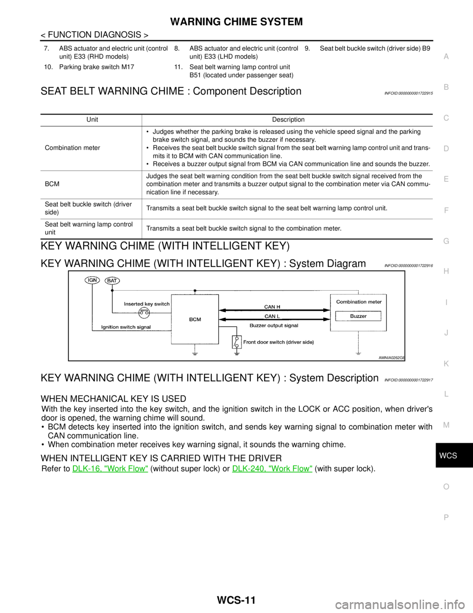
KEY WARNING CHIME (WITH INTELLIGENT KEY) : System DiagramINFOID:0000000001722916
KEY WARNING CHIME (WITH INTELLIGENT KEY) : System DescriptionINFOID:0000000001722917
WHEN MECHANICAL KEY IS USED
With the key inserted into the key switch, and the ignition switch in the LOCK or ACC position, when driver's
door is opened, the warning chime will sound.
BCM detects key inserted into the ignition switch, and sends key warning signal to combination meter with
CAN communication line.
When combination meter receives key warning signal, it sounds the warning chime.
WHEN INTELLIGENT KEY IS CARRIED WITH THE DRIVER
Refer to DLK-16, "Work Flow" (without super lock) or DLK-240, "Work Flow" (with super lock).
7. ABS actuator and electric unit (control
unit) E33 (RHD models)8. ABS actuator and electric unit (control
unit) E33 (LHD models)9. Seat belt buckle switch (driver side) B9
10. Parking brake switch M17 11. Seat belt warning lamp control unit
B51 (located under passenger seat)
Unit Description
Combination meter Judges whether the parking brake is released using the vehicle speed signal and the parking
brake switch signal, and sounds the buzzer if necessary.
Receives the seat belt buckle switch signal from the seat belt warning lamp control unit and trans-
mits it to BCM with CAN communication line.
Receives a buzzer output signal from BCM via CAN communication line and sounds the buzzer.
BCMJudges the seat belt warning condition from the seat belt buckle switch signal received from the
combination meter and transmits a buzzer output signal to the combination meter via CAN commu-
nication line if necessary.
Seat belt buckle switch (driver
side)Transmits a seat belt buckle switch signal to the seat belt warning lamp control unit.
Seat belt warning lamp control
unitTransmits a seat belt buckle switch signal to the combination meter.
AWNIA0262GB