Page 4321 of 5883
MWI-14
< FUNCTION DIAGNOSIS >
METER SYSTEM
ODO/TRIP METER : Component Parts Location
INFOID:0000000001537310
1. Combination meter M24 2. ABS actuator and electric unit (control
unit) E33 (RHD models) (MR18DE
shown, HR16DE and K9K similar)3. IPDM E/R E43, E46, E48 (MR18DE
shown, HR16DE and K9K similar)
4. ECM E16 (MR18DE shown, HR16DE
and K9K similar)5. ABS actuator and electric unit (control
unit) E33 (LHD models)6. Fuel level sensor unit and fuel pump
B40 (view with rear seat and inspection
hole cover removed)
⇐: Front
7. Oil pressure switch F32 (HR16DE and
MR18DE models) (view with engine re-
moved)8. Oil level sensor F60 (HR16DE and
MR18DE models) (view with engine re-
moved)9. Oil pressure switch F32 (K9K models)
(view with engine removed)
10. Oil level sensor F60 (K9K models)
(view with engine removed)
ALNIA0624ZZ
Page 4322 of 5883

MWI
METER SYSTEM
MWI-15
< FUNCTION DIAGNOSIS >
C
D
E
F
G
H
I
J
K
L
MB A
O
P
ODO/TRIP METER : Component DescriptionINFOID:0000000001537302
WARNING LAMPS/INDICATOR LAMPS
WARNING LAMPS/INDICATOR LAMPS : System DiagramINFOID:0000000001537297
WARNING LAMPS/INDICATOR LAMPS : System DescriptionINFOID:0000000001537298
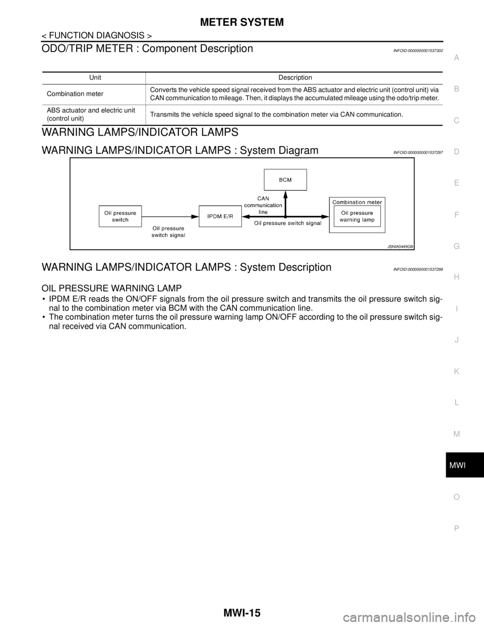
OIL PRESSURE WARNING LAMP
IPDM E/R reads the ON/OFF signals from the oil pressure switch and transmits the oil pressure switch sig-
nal to the combination meter via BCM with the CAN communication line.
The combination meter turns the oil pressure warning lamp ON/OFF according to the oil pressure switch sig-
nal received via CAN communication.
Unit Description
Combination meterConverts the vehicle speed signal received from the ABS actuator and electric unit (control unit) via
CAN communication to mileage. Then, it displays the accumulated mileage using the odo/trip meter.
ABS actuator and electric unit
(control unit)Transmits the vehicle speed signal to the combination meter via CAN communication.
JSNIA0449GB
Page 4323 of 5883
MWI-16
< FUNCTION DIAGNOSIS >
METER SYSTEM
WARNING LAMPS/INDICATOR LAMPS : Component Parts Location
INFOID:0000000001537311
1. Combination meter M24 2. ABS actuator and electric unit (control
unit) E33 (RHD models) (MR18DE
shown, HR16DE and K9K similar)3. IPDM E/R E43, E46, E48 (MR18DE
shown, HR16DE and K9K similar)
4. ECM E16 (MR18DE shown, HR16DE
and K9K similar)5. ABS actuator and electric unit (control
unit) E33 (LHD models)6. Fuel level sensor unit and fuel pump
B40 (view with rear seat and inspection
hole cover removed)
⇐: Front
7. Oil pressure switch F32 (HR16DE and
MR18DE models) (view with engine re-
moved)8. Oil level sensor F60 (HR16DE and
MR18DE models) (view with engine re-
moved)9. Oil pressure switch F32 (K9K models)
(view with engine removed)
10. Oil level sensor F60 (K9K models)
(view with engine removed)
ALNIA0624ZZ
Page 4325 of 5883

MWI-18
< FUNCTION DIAGNOSIS >
METER SYSTEM
The distance to empty indication provides the driver with an estimation of the distance that can be driven
before refueling. The distance to empty is calculated using signals from the fuel level sensor unit (fuel remain-
ing), ECM (fuel consumption) and vehicle speed signals from the ABS actuator and electric unit (control unit).
JOURNY TIME
The travel time since last reset is displayed.
AVERAGE FUEL CONSUMTION
Average fuel consumption indication is calculated using vehicle speed signals from the ABS actuator and elec-
tric unit (control unit) and fuel consumption information from the ECM.
AVERAGE SPEED
The average speed mode can be selected to display the average speed since last reset. The indications are
calculated using vehicle speed signals from the ABS actuator and electric unit (control unit).
OUTSIDE AIR TEMPERATURE
The combination meter indicates the outside air temperature calculated by the temperature signal received
from the ambient sensor.
The indicated temperature is not readily affected by engine heat. It changes only when one of the following
conditions is present.
The temperature detected by the ambient sensor is lower than the indicated temperature
The vehicle speed is greater than 20 km/h (13 MPH)
(This is to prevent the indicated temperature from being affected by engine heat during low-speed driving.)
The ignition switch has been turned to the OFF position for more than 3.5 hours. (The engine is cold.)
When the ambient air temperature falls below 3°C (37°F), the display starts flashing. Approximately 20 sec-
onds later, only “°C” flashes.
NOTE:
On vehicles equipped with auto A/C, the ambient sensor signal is shared with the front air control. The combi-
nation meter is notified of the signal sharing via the auto A/C sense circuit.
Page 4326 of 5883
MWI
METER SYSTEM
MWI-19
< FUNCTION DIAGNOSIS >
C
D
E
F
G
H
I
J
K
L
MB A
O
P
INFORMATION DISPLAY : Component Parts LocationINFOID:0000000001537312
INFORMATION DISPLAY : Component DescriptionINFOID:0000000001537301
1. Combination meter M24 2. ABS actuator and electric unit (control
unit) E33 (RHD models) (MR18DE
shown, HR16DE and K9K similar)3. IPDM E/R E43, E46, E48 (MR18DE
shown, HR16DE and K9K similar)
4. ECM E16 (MR18DE shown, HR16DE
and K9K similar)5. ABS actuator and electric unit (control
unit) E33 (LHD models)6. Fuel level sensor unit and fuel pump
B40 (view with rear seat and inspection
hole cover removed)
⇐: Front
7. Oil pressure switch F32 (HR16DE and
MR18DE models) (view with engine re-
moved)8. Oil level sensor F60 (HR16DE and
MR18DE models) (view with engine re-
moved)9. Oil pressure switch F32 (K9K models)
(view with engine removed)
10. Oil level sensor F60 (K9K models)
(view with engine removed)
ALNIA0624ZZ
Page 4327 of 5883
MWI-20
< FUNCTION DIAGNOSIS >
METER SYSTEM
Unit Description
Combination meter Controls the information display according to the signal received from each unit.
Fuel level sensor unit Refer to MWI-29, "
Description".
ECMTransmits the following signals to the combination meter via CAN communication line.
Engine speed signal Fuel consumption monitor signal
ABS actuator and electric unit
(control unit)Transmits the vehicle speed signal to the combination meter via CAN communication line.
Ambient sensor Refer to MWI-34, "
Description".
Oil level sensor Refer to MWI-32, "
Description".
Page 4330 of 5883

MWI
DIAGNOSIS SYSTEM (METER)
MWI-23
< FUNCTION DIAGNOSIS >
C
D
E
F
G
H
I
J
K
L
MB A
O
P
NOTE:
Some items are not available due to vehicle specification.
*: The monitor will indicate “OFF” even though the brake warning lamp is on if either of the following conditions exist.
The parking brake is engaged
The brake fluid level is lowDOOR W/L [ON/OFF] X Displays [ON/OFF] condition of door warning lamp.
HI-BEAM IND [ON/OFF] X Displays [ON/OFF] condition of high beam indicator.
TURN IND [ON/OFF] X Displays [ON/OFF] condition of turn indicator.
FR FOG IND X Displays [ON/OFF] condition of front fog lamp indicator.
RR FOG IND X Displays [ON/OFF] condition of rear fog lamp indicator.
OIL W/L [ON/OFF] X Displays [ON/OFF] condition of oil pressure warning lamp.
LIGHT IND X Displays [ON/OFF] condition of exterior lamp indicator.
VDC/TCS IND [ON/OFF] X Displays [ON/OFF] condition of VDC OFF indicator lamp.
ABS W/L [ON/OFF] X Displays [ON/OFF] condition of ABS warning lamp.
SLIP IND [ON/OFF] X Displays [ON/OFF] condition of SLIP indicator lamp.
BRAKE W/L [ON/OFF] X Displays [ON/OFF] condition of brake warning lamp.*
OIL LEVEL IND X Displays [ON/OFF] condition of oil level indicator.
KEY G W/L [ON/OFF] X Displays [ON/OFF] condition of key green warning lamp.
KEY R W/L [ON/OFF] X Displays [ON/OFF] condition of key red warning lamp.
KEY KNOB W/L [ON/OFF] X Displays [ON/OFF] condition of key knob warning lamp.
PNP P SW X X Displays [ON/OFF] condition of inhibitor P switch.
PNP N SW X X Displays [ON/OFF] condition of inhibitor N switch.
O/D OFF SW X Displays [ON/OFF] condition of O/D OFF switch.
BRAKE SW [ON/OFF] X Displays [ON/OFF] condition of parking brake switch.
P RANGE IND [ON/OFF] X X Displays [ON/OFF] condition of A/T shift P range indicator.
R RANGE IND [ON/OFF] X X Displays [ON/OFF] condition of A/T shift R range indicator.
N RANGE IND [ON/OFF] X X Displays [ON/OFF] condition of A/T shift N range indicator.
D RANGE IND [ON/OFF] X X Displays [ON/OFF] condition of A/T shift D range indicator.
2 RANGE IND [ON/OFF] X X Displays [ON/OFF] condition of A/T shift 2 range indicator.
1 RANGE IND [ON/OFF] X X Displays [ON/OFF] condition of A/T shift 1range indicator.
O/D OFF W/L X Displays [ON/OFF] condition of O/D OFF indicator lamp.
CRUISE IND [ON/OFF] X Displays [ON/OFF] condition of CRUISE indicator.
EPS W/L X Displays [ON/OFF] condition of EPS warning lamp. Display item [Unit]MAIN
SIGNALSSELECTION
FROM MENUDescription
Page 4332 of 5883

MWI
DTC B2205 VEHICLE SPEED CIRCUIT
MWI-25
< COMPONENT DIAGNOSIS >
C
D
E
F
G
H
I
J
K
L
MB A
O
P
DTC B2205 VEHICLE SPEED CIRCUIT
DescriptionINFOID:0000000001374685
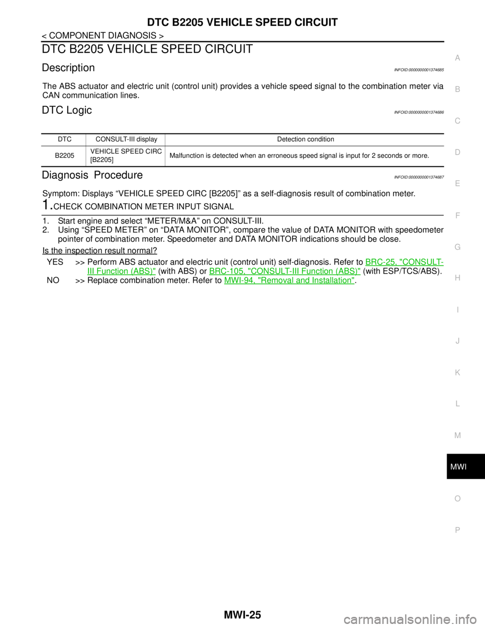
The ABS actuator and electric unit (control unit) provides a vehicle speed signal to the combination meter via
CAN communication lines.
DTC LogicINFOID:0000000001374686
Diagnosis ProcedureINFOID:0000000001374687
Symptom: Displays “VEHICLE SPEED CIRC [B2205]” as a self-diagnosis result of combination meter.
1.CHECK COMBINATION METER INPUT SIGNAL
1. Start engine and select “METER/M&A” on CONSULT-III.
2. Using “SPEED METER” on “DATA MONITOR”, compare the value of DATA MONITOR with speedometer
pointer of combination meter. Speedometer and DATA MONITOR indications should be close.
Is the inspection result normal?
YES >> Perform ABS actuator and electric unit (control unit) self-diagnosis. Refer to BRC-25, "CONSULT-
III Function (ABS)" (with ABS) or BRC-105, "CONSULT-III Function (ABS)" (with ESP/TCS/ABS).
NO >> Replace combination meter. Refer to MWI-94, "
Removal and Installation".
DTC CONSULT-III display Detection condition
B2205VEHICLE SPEED CIRC
[B2205]Malfunction is detected when an erroneous speed signal is input for 2 seconds or more.