Page 4296 of 5883
MA-56
< ON-VEHICLE MAINTENANCE >
CHASSIS AND BODY MAINTENANCE
Check the brake pads for wear or damage. Refer to BR-24,
"Removal and Installation of Brake Pad" .
Axle and Suspension PartsINFOID:0000000001730909
Check front and rear axle and suspension parts for excessive play,
cracks, wear or other damage.
Shake each wheel to check for excessive play.
Check wheel bearings for smooth operation.
Check axle and suspension nuts and bolts for looseness.
Check strut (shock absorber) for oil leakage or other damage.
Check suspension ball joint for grease leakage and ball joint dust
cover for cracks or other damage.
Drive ShaftINFOID:0000000001730910
Check boot and drive shaft for cracks, wear, damage and grease
leakage.
BRA0010D
SMA525A
SFA392B
SDIA1190J
Page 4306 of 5883

MIR-8
< REMOVAL AND INSTALLATION >
DOOR MIRROR
Disassembly and Assembly
INFOID:0000000001716809
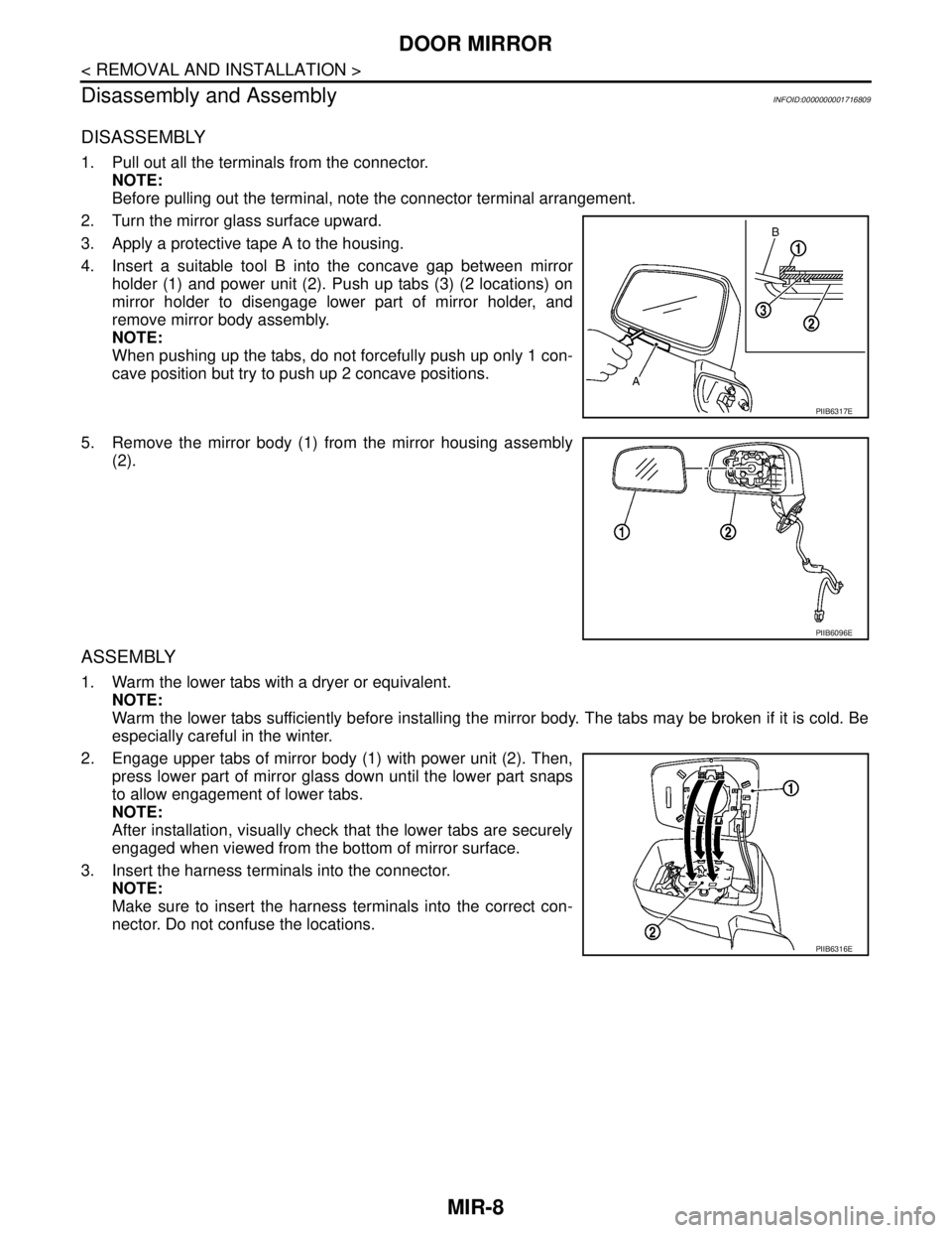
DISASSEMBLY
1. Pull out all the terminals from the connector.
NOTE:
Before pulling out the terminal, note the connector terminal arrangement.
2. Turn the mirror glass surface upward.
3. Apply a protective tape A to the housing.
4. Insert a suitable tool B into the concave gap between mirror
holder (1) and power unit (2). Push up tabs (3) (2 locations) on
mirror holder to disengage lower part of mirror holder, and
remove mirror body assembly.
NOTE:
When pushing up the tabs, do not forcefully push up only 1 con-
cave position but try to push up 2 concave positions.
5. Remove the mirror body (1) from the mirror housing assembly
(2).
ASSEMBLY
1. Warm the lower tabs with a dryer or equivalent.
NOTE:
Warm the lower tabs sufficiently before installing the mirror body. The tabs may be broken if it is cold. Be
especially careful in the winter.
2. Engage upper tabs of mirror body (1) with power unit (2). Then,
press lower part of mirror glass down until the lower part snaps
to allow engagement of lower tabs.
NOTE:
After installation, visually check that the lower tabs are securely
engaged when viewed from the bottom of mirror surface.
3. Insert the harness terminals into the connector.
NOTE:
Make sure to insert the harness terminals into the correct con-
nector. Do not confuse the locations.
PIIB6317E
PIIB6096E
PIIB6316E
Page 4313 of 5883
MWI-6
< FUNCTION DIAGNOSIS >
METER SYSTEM
METER SYSTEM : Component Parts Location
INFOID:0000000001374649
1. Combination meter M24 2. ABS actuator and electric unit (control
unit) E33 (RHD models) (MR18DE
shown, HR16DE and K9K similar)3. IPDM E/R E43, E46, E48 (MR18DE
shown, HR16DE and K9K similar)
4. ECM E16 (MR18DE shown, HR16DE
and K9K similar)5. ABS actuator and electric unit (control
unit) E33 (LHD models)6. Fuel level sensor unit and fuel pump
B40 (view with rear seat and inspection
hole cover removed)
⇐: Front
7. Oil pressure switch F32 (HR16DE and
MR18DE models) (view with engine re-
moved)8. Oil level sensor F60 (HR16DE and
MR18DE models) (view with engine re-
moved)9. Oil pressure switch F32 (K9K models)
(view with engine removed)
10. Oil level sensor F60 (K9K models)
(view with engine removed)
ALNIA0624ZZ
Page 4314 of 5883

MWI
METER SYSTEM
MWI-7
< FUNCTION DIAGNOSIS >
C
D
E
F
G
H
I
J
K
L
MB A
O
P
METER SYSTEM : Component DescriptionINFOID:0000000001537306
SPEEDOMETER
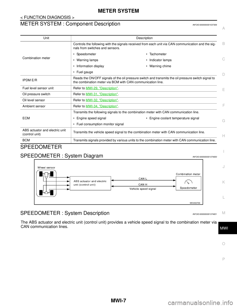
SPEEDOMETER : System DiagramINFOID:0000000001374650
SPEEDOMETER : System DescriptionINFOID:0000000001374651
The ABS actuator and electric unit (control unit) provides a vehicle speed signal to the combination meter via
CAN communication lines.
Unit Description
Combination meterControls the following with the signals received from each unit via CAN communication and the sig-
nals from switches and sensors.
Speedometer Tachometer
Warning lamps Indicator lamps
Information display Warning chime
Fuel gauge
IPDM E/RReads the ON/OFF signals of the oil pressure switch and transmits the oil pressure switch signal to
the combination meter via BCM with CAN communication line.
Fuel level sensor unit Refer to MWI-29, "
Description".
Oil pressure switch Refer to MWI-31, "
Description".
Oil level sensor Refer to MWI-32, "
Description".
Ambient sensor Refer to MWI-34, "
Description".
ECMTransmits the following signals to the combination meter with CAN communication line.
Engine speed signal Engine coolant temperature signal
Fuel consumption monitor signal
ABS actuator and electric unit
(control unit)Transmits the vehicle speed signal to the combination meter with CAN communication line.
BCM Transmits signals provided by various units to the combination meter with CAN communication line.
WKIA5370E
Page 4315 of 5883
MWI-8
< FUNCTION DIAGNOSIS >
METER SYSTEM
SPEEDOMETER : Component Parts Location
INFOID:0000000001537307
1. Combination meter M24 2. ABS actuator and electric unit (control
unit) E33 (RHD models) (MR18DE
shown, HR16DE and K9K similar)3. IPDM E/R E43, E46, E48 (MR18DE
shown, HR16DE and K9K similar)
4. ECM E16 (MR18DE shown, HR16DE
and K9K similar)5. ABS actuator and electric unit (control
unit) E33 (LHD models)6. Fuel level sensor unit and fuel pump
B40 (view with rear seat and inspection
hole cover removed)
⇐: Front
7. Oil pressure switch F32 (HR16DE and
MR18DE models) (view with engine re-
moved)8. Oil level sensor F60 (HR16DE and
MR18DE models) (view with engine re-
moved)9. Oil pressure switch F32 (K9K models)
(view with engine removed)
10. Oil level sensor F60 (K9K models)
(view with engine removed)
ALNIA0624ZZ
Page 4316 of 5883
MWI
METER SYSTEM
MWI-9
< FUNCTION DIAGNOSIS >
C
D
E
F
G
H
I
J
K
L
MB A
O
P
SPEEDOMETER : Component DescriptionINFOID:0000000001537305
TACHOMETER
TACHOMETER : System DiagramINFOID:0000000001374653
TACHOMETER : System DescriptionINFOID:0000000001374654
The tachometer indicates engine speed in revolutions per minute (rpm).
The ECM provides an engine speed signal to the combination meter via CAN communication lines.
Unit Description
Combination meterIndicates the vehicle speed according to the vehicle speed signal received from ABS actuator and
electric unit (control unit) via CAN communication.
ABS actuator and electric unit
(control unit)Transmits the vehicle speed signal to the combination meter with CAN communication line.
SKIB6904E
Page 4317 of 5883
MWI-10
< FUNCTION DIAGNOSIS >
METER SYSTEM
TACHOMETER : Component Parts Location
INFOID:0000000001537308
1. Combination meter M24 2. ABS actuator and electric unit (control
unit) E33 (RHD models) (MR18DE
shown, HR16DE and K9K similar)3. IPDM E/R E43, E46, E48 (MR18DE
shown, HR16DE and K9K similar)
4. ECM E16 (MR18DE shown, HR16DE
and K9K similar)5. ABS actuator and electric unit (control
unit) E33 (LHD models)6. Fuel level sensor unit and fuel pump
B40 (view with rear seat and inspection
hole cover removed)
⇐: Front
7. Oil pressure switch F32 (HR16DE and
MR18DE models) (view with engine re-
moved)8. Oil level sensor F60 (HR16DE and
MR18DE models) (view with engine re-
moved)9. Oil pressure switch F32 (K9K models)
(view with engine removed)
10. Oil level sensor F60 (K9K models)
(view with engine removed)
ALNIA0624ZZ
Page 4319 of 5883
MWI-12
< FUNCTION DIAGNOSIS >
METER SYSTEM
FUEL GAUGE : Component Parts Location
INFOID:0000000001537309
1. Combination meter M24 2. ABS actuator and electric unit (control
unit) E33 (RHD models) (MR18DE
shown, HR16DE and K9K similar)3. IPDM E/R E43, E46, E48 (MR18DE
shown, HR16DE and K9K similar)
4. ECM E16 (MR18DE shown, HR16DE
and K9K similar)5. ABS actuator and electric unit (control
unit) E33 (LHD models)6. Fuel level sensor unit and fuel pump
B40 (view with rear seat and inspection
hole cover removed)
⇐: Front
7. Oil pressure switch F32 (HR16DE and
MR18DE models) (view with engine re-
moved)8. Oil level sensor F60 (HR16DE and
MR18DE models) (view with engine re-
moved)9. Oil pressure switch F32 (K9K models)
(view with engine removed)
10. Oil level sensor F60 (K9K models)
(view with engine removed)
ALNIA0624ZZ