2007 NISSAN TIIDA display
[x] Cancel search: displayPage 3028 of 5883
DIAGNOSIS SYSTEM (BCM)
EXL-27
< FUNCTION DIAGNOSIS >
C
D
E
F
G
H
I
J
K
MA
B
EXL
N
O
P
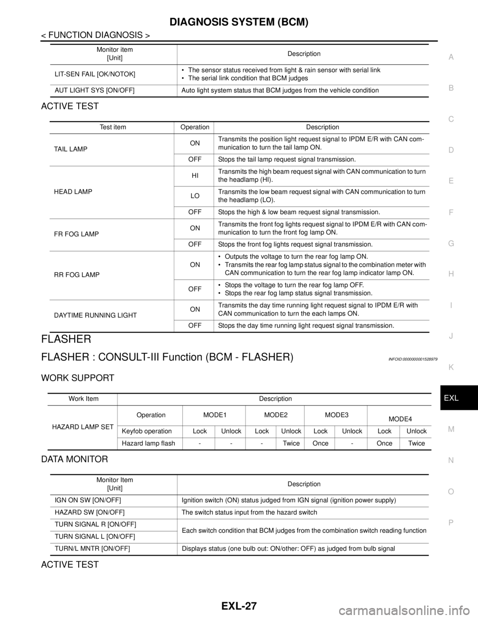
ACTIVE TEST
FLASHER
FLASHER : CONSULT-III Function (BCM - FLASHER)INFOID:0000000001528979
WORK SUPPORT
DATA MONITOR
ACTIVE TEST
LIT-SEN FAIL [OK/NOTOK] The sensor status received from light & rain sensor with serial link
The serial link condition that BCM judges
AUT LIGHT SYS [ON/OFF] Auto light system status that BCM judges from the vehicle conditionMonitor item
[Unit]Description
Test item Operation Description
TAIL LAMPONTransmits the position light request signal to IPDM E/R with CAN com-
munication to turn the tail lamp ON.
OFF Stops the tail lamp request signal transmission.
HEAD LAMPHITransmits the high beam request signal with CAN communication to turn
the headlamp (HI).
LOTransmits the low beam request signal with CAN communication to turn
the headlamp (LO).
OFF Stops the high & low beam request signal transmission.
FR FOG LAMPONTransmits the front fog lights request signal to IPDM E/R with CAN com-
munication to turn the front fog lamp ON.
OFF Stops the front fog lights request signal transmission.
RR FOG LAMPON Outputs the voltage to turn the rear fog lamp ON.
Transmits the rear fog lamp status signal to the combination meter with
CAN communication to turn the rear fog lamp indicator lamp ON.
OFF Stops the voltage to turn the rear fog lamp OFF.
Stops the rear fog lamp status signal transmission.
DAYTIME RUNNING LIGHTONTransmits the day time running light request signal to IPDM E/R with
CAN communication to turn the each lamps ON.
OFF Stops the day time running light request signal transmission.
Work Item Description
HAZARD LAMP SETOperation MODE1 MODE2 MODE3
MODE4
Keyfob operation Lock Unlock Lock Unlock Lock Unlock Lock Unlock
Hazard lamp flash - - - Twice Once - Once Twice
Monitor Item
[Unit]Description
IGN ON SW [ON/OFF] Ignition switch (ON) status judged from IGN signal (ignition power supply)
HAZARD SW [ON/OFF] The switch status input from the hazard switch
TURN SIGNAL R [ON/OFF]
Each switch condition that BCM judges from the combination switch reading function
TURN SIGNAL L [ON/OFF]
TURN/L MNTR [ON/OFF] Displays status (one bulb out: ON/other: OFF) as judged from bulb signal
Page 3029 of 5883

EXL-28
< FUNCTION DIAGNOSIS >
DIAGNOSIS SYSTEM (BCM)
COMB SW
COMB SW : CONSULT-III Function (BCM - COMB SW)INFOID:0000000001528982
DATA MONITOR
BATTERY SAVER
BATTERY SAVER : CONSULT-III Function (BCM - BATTERY SAVER)INFOID:0000000001528984
WORK SUPPORT
Test Item Operation Description
FLASHERRH Outputs the voltage to turn the right side turn signal lamps ON.
LH Outputs the voltage to turn the left side turn signal lamps ON.
OFF Stops the voltage to turn the turn signal lamps OFF.
Monitor Item
[Unit]Description
TURN SIGNAL R
[OFF/ON]Displays the status of the TURN RH switch in combination switch judged by BCM with the combination switch
reading function.
TURN SIGNAL L
[OFF/ON]Displays the status of the TURN LH switch in combination switch judged by BCM with the combination switch
reading function.
HI BEAM SW
[OFF/ON]Displays the status of the HI BEAM switch in combination switch judged by BCM with the combination switch
reading function.
H/L SW POS
[OFF/ON]Displays the status of the HEADLAMP switch in combination switch judged by BCM with the combination
switch reading function.
LIGHT SW 1ST
[OFF/ON]Displays the status of the HEADLAMP switch in combination switch judged by BCM with the combination
switch reading function.
PASSING SW
[OFF/ON]Displays the status of the PASSING switch in combination switch judged by BCM with the combination switch
reading function.
AUTO LIGHT SW
[OFF/ON]Displays the status of the AUTO LIGHT switch in combination switch judged by BCM with the combination
switch reading function.
FR FOG SW
[OFF/ON]Displays the status of the FR FOG switch in combination switch judged by BCM with the combination switch
reading function.
RR FOG SW
[OFF/ON]Displays the status of the RR FOG switch in combination switch judged by BCM with the combination switch
reading function.
FR WIPER HI
[OFF/ON]Displays the status of the FR WIPER HI switch in combination switch judged by BCM with the combination
switch reading function.
FR WIPER LOW
[OFF/ON]Displays the status of the FR WIPER LOW switch in combination switch judged by BCM with the combination
switch reading function.
FR WIPER INT
[OFF/ON]Displays the status of the FR WIPER INT switch in combination switch judged by BCM with the combination
switch reading function.
FR WASHER SW
[OFF/ON]Displays the status of the FR WASHER switch in combination switch judged by BCM with the combination
switch reading function.
INT VOLUME
[1 - 7]Displays the status of wiper intermittent dial position judged by BCM with the combination switch reading
function.
RR WIPER ON
[OFF/ON]Displays the status of the RR WIPER switch in combination switch judged by BCM with the combination
switch reading function.
RR WIPER INT
[OFF/ON]Displays the status of the RR WIPER INT switch in combination switch judged by BCM with the combination
switch reading function.
RR WASHER SW
[OFF/ON]Displays the status of the RR WASHER switch in combination switch judged by BCM with the combination
switch reading function.
Page 3031 of 5883

EXL-30
< FUNCTION DIAGNOSIS >
DIAGNOSIS SYSTEM (IPDM E/R)
DIAGNOSIS SYSTEM (IPDM E/R)
CONSULT - III Function (IPDM E/R)INFOID:0000000001523254
APPLICATION ITEM
CONSULT-III performs the following functions via CAN communication with IPDM E/R.
DATA MONITOR
Monitor item
ACTIVE TEST
Te s t i t e m
Diagnosis mode Description
SELF-DIAG RESULTS Displays the diagnosis results judged by IPDM E/R.
DATA MONITOR Displays the real-time input/output data from IPDM E/R input/output data.
ACTIVE TEST IPDM E/R can provide a drive signal to electronic components to check their operations.
CAN DIAG SUPPORT MONITOR The results of transmit/receive diagnosis of CAN communication can be read.
Monitor Item
[Unit]MAIN SIG-
NALSDescription
HL LO REQ
[Off/On]×Displays the status of the low beam request signal received from BCM via CAN
communication.
HL HI REQ
[Off/On]×Displays the status of the high beam request signal received from BCM via CAN
communication.
FR FOG REQ
[Off/On]×Displays the status of the front fog light request signal received from BCM via
CAN communication.
TAIL & CLR REQ
[Off/On]xDisplays the status of the tail and clearance lamp request signal received from
BCM via CAN communication.
DTRL REQ
[Off]NOTE:
The item is indicated, but not monitored.
Test item Operation Description
EXTERNAL LAMPSOff OFF
TAIL Operates the tail lamp relay.
Lo Operates the headlamp low relay.
HiOperates the headlamp low relay and ON/OFF the headlamp high relay at 1 sec-
ond intervals.
Fog Operates the front fog lamp relay.
Page 3032 of 5883
DIAGNOSIS SYSTEM (HEADLAMP LEVELIZER)
EXL-31
< FUNCTION DIAGNOSIS >
C
D
E
F
G
H
I
J
K
MA
B
EXL
N
O
P
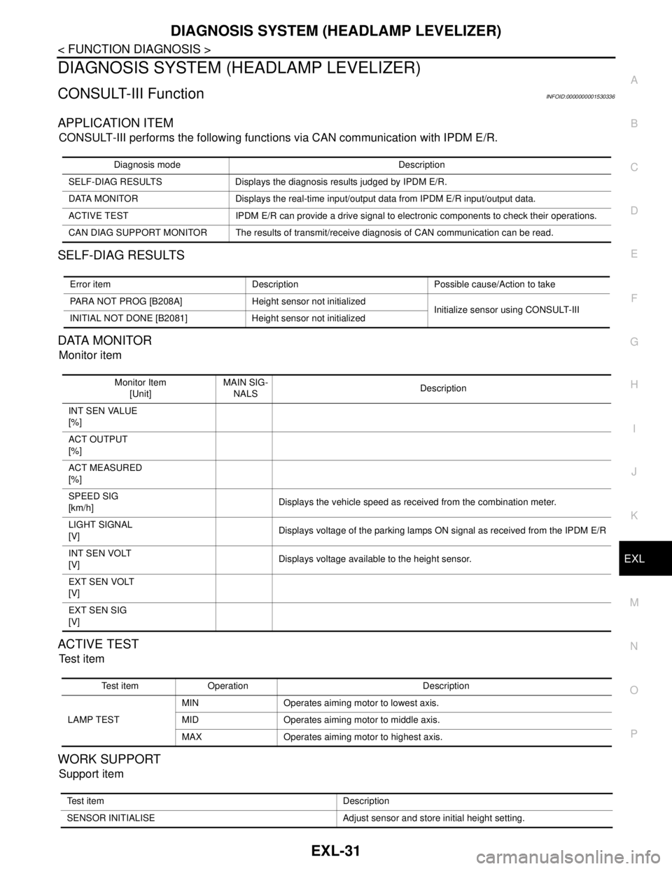
DIAGNOSIS SYSTEM (HEADLAMP LEVELIZER)
CONSULT-III FunctionINFOID:0000000001530336
APPLICATION ITEM
CONSULT-III performs the following functions via CAN communication with IPDM E/R.
SELF-DIAG RESULTS
DATA MONITOR
Monitor item
ACTIVE TEST
Te s t i t e m
WORK SUPPORT
Support item
Diagnosis mode Description
SELF-DIAG RESULTS Displays the diagnosis results judged by IPDM E/R.
DATA MONITOR Displays the real-time input/output data from IPDM E/R input/output data.
ACTIVE TEST IPDM E/R can provide a drive signal to electronic components to check their operations.
CAN DIAG SUPPORT MONITOR The results of transmit/receive diagnosis of CAN communication can be read.
Error item Description Possible cause/Action to take
PARA NOT PROG [B208A] Height sensor not initialized
Initialize sensor using CONSULT-III
INITIAL NOT DONE [B2081] Height sensor not initialized
Monitor Item
[Unit]MAIN SIG-
NALSDescription
INT SEN VALUE
[%]
ACT OUTPUT
[%]
ACT MEASURED
[%]
SPEED SIG
[km/h]Displays the vehicle speed as received from the combination meter.
LIGHT SIGNAL
[V]Displays voltage of the parking lamps ON signal as received from the IPDM E/R
INT SEN VOLT
[V]Displays voltage available to the height sensor.
EXT SEN VOLT
[V]
EXT SEN SIG
[V]
Test item Operation Description
LAMP TESTMIN Operates aiming motor to lowest axis.
MID Operates aiming motor to middle axis.
MAX Operates aiming motor to highest axis.
Test item Description
SENSOR INITIALISE Adjust sensor and store initial height setting.
Page 3182 of 5883
FSU-6
< ON-VEHICLE MAINTENANCE >
FRONT SUSPENSION ASSEMBLY
ON-VEHICLE MAINTENANCE
FRONT SUSPENSION ASSEMBLY
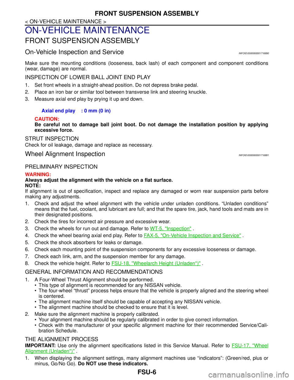
On-Vehicle Inspection and ServiceINFOID:0000000001716890
Make sure the mounting conditions (looseness, back lash) of each component and component conditions
(wear, damage) are normal.
INSPECTION OF LOWER BALL JOINT END PLAY
1. Set front wheels in a straight-ahead position. Do not depress brake pedal.
2. Place an iron bar or similar tool between transverse link and steering knuckle.
3. Measure axial end play by prying it up and down.
CAUTION:
Be careful not to damage ball joint boot. Do not damage the installation position by applying
excessive force.
STRUT INSPECTION
Check for oil leakage, damage and replace as necessary.
Wheel Alignment InspectionINFOID:0000000001716891
PRELIMINARY INSPECTION
WARNING:
Always adjust the alignment with the vehicle on a flat surface.
NOTE:
If alignment is out of specification, inspect and replace any damaged or worn rear suspension parts before
making any adjustments.
1. Check and adjust the wheel alignment with the vehicle under unladen conditions. “Unladen conditions”
means that the fuel, coolant, and lubricant are full; and that the spare tire, jack, hand tools and mats are in
their designated positions.
2. Check the tires for incorrect air pressure and excessive wear.
3. Check the wheels for run out and damage. Refer to WT-5, "
Inspection" .
4. Check the wheel bearing axial end play. Refer to FA X - 5 , "
On-Vehicle Inspection and Service" .
5. Check the shock absorbers for leaks or damage.
6. Check each mounting point of the suspension components for any excessive looseness or damage.
7. Check each link, arm, and the suspension member for any damage.
8. Check the vehicle height. Refer to FSU-18, "
Wheelarch Height (Unladen*)" .
GENERAL INFORMATION AND RECOMMENDATIONS
1. A Four-Wheel Thrust Alignment should be performed.
This type of alignment is recommended for any NISSAN vehicle.
The four-wheel “thrust” process helps ensure that the vehicle is properly aligned and the steering wheel
is centered.
The alignment machine itself should be capable of accepting any NISSAN vehicle.
The alignment machine should be checked to ensure that it is level.
2. Make sure the alignment machine is properly calibrated.
Your alignment machine should be regularly calibrated in order to give correct information.
Check with the manufacturer of your specific alignment machine for their recommended Service/Cali-
bration Schedule.
THE ALIGNMENT PROCESS
IMPORTANT: Use only the alignment specifications listed in this Service Manual. Refer to FSU-17, "Wheel
Alignment (Unladen*)" .
1. When displaying the alignment settings, many alignment machines use “indicators”: (Green/red, plus or
minus, Go/No Go). Do NOT use these indicators. Axial end play : 0 mm (0 in)
Page 3257 of 5883
CONSULT-III CHECKING SYSTEM
GI-63
< BASIC INSPECTION >
C
D
E
F
G
H
I
J
K
L
MB
GI
N
O
PCONSULT-III CHECKING SYSTEM
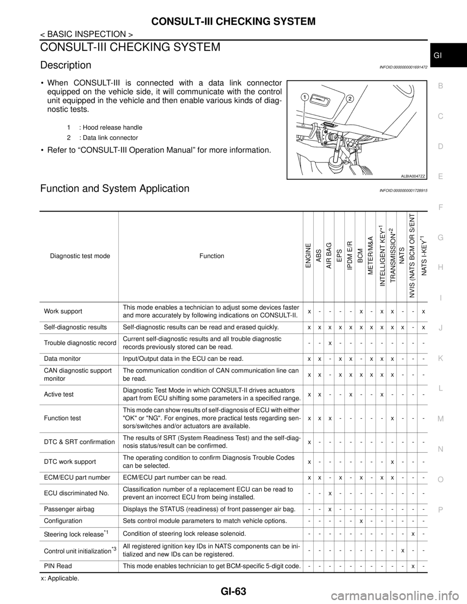
DescriptionINFOID:0000000001691472
When CONSULT-III is connected with a data link connector
equipped on the vehicle side, it will communicate with the control
unit equipped in the vehicle and then enable various kinds of diag-
nostic tests.
Refer to “CONSULT-III Operation Manual” for more information.
Function and System ApplicationINFOID:0000000001728915
x: Applicable.1 : Hood release handle
2 : Data link connector
ALBIA0047ZZ
Diagnostic test mode Function
ENGINE
ABS
AIR BAG
EPS
IPDM E/R
BCM
METER/M&A
INTELLIGENT KEY*
1
TRANSMISSION*
2
NATS
NVIS (NATS BCM OR S/ENT
NATS I-KEY
*1
Work supportThis mode enables a technician to adjust some devices faster
and more accurately by following indications on CONSULT-II.x----x-xx--x
Self-diagnostic results Self-diagnostic results can be read and erased quickly. xxxxxxxxxx - x
Trouble diagnostic recordCurrent self-diagnostic results and all trouble diagnostic
records previously stored can be read.--x---------
Data monitor Input/Output data in the ECU can be read. x x - x x - x x x - - -
CAN diagnostic support
monitorThe communication condition of CAN communication line can
be read.xx - xxxxxx - - -
Active testDiagnostic Test Mode in which CONSULT-II drives actuators
apart from ECU shifting some parameters in a specified range.xx--x--x----
Function testThis mode can show results of self-diagnosis of ECU with either
"OK" or "NG". For engines, more practical tests regarding sen-
sors/switches and/or actuators are available.xxx-----x---
DTC & SRT confirmationThe results of SRT (System Readiness Test) and the self-diag-
nosis status/result can be confirmed.x-----------
DTC work supportThe operating condition to confirm Diagnosis Trouble Codes
can be selected.x-------x---
ECM/ECU part number ECM/ECU part number can be read. x x - x - x - x x - - -
ECU discriminated No.Classification number of a replacement ECU can be read to
prevent an incorrect ECU from being installed.--x---------
Passenger airbag Displays the STATUS (readiness) of front passenger air bag. --x---------
Configuration Sets control module parameters to match vehicle options. -----x------
Steering lock release
*1Condition of steering lock release solenoid. ----------x-
Control unit initialization
*3All registered ignition key IDs in NATS components can be ini-
tialized and new IDs can be registered.---------x--
PIN Read This mode enables technician to get BCM-specific 5-digit code.----------x-
Page 3292 of 5883
HA-10
< PRECAUTION >
PRECAUTIONS
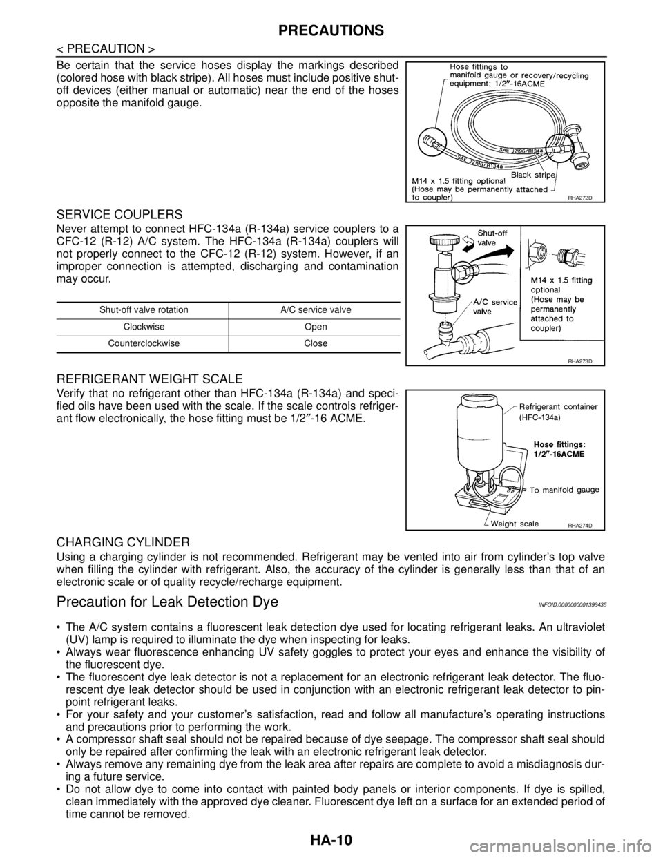
Be certain that the service hoses display the markings described
(colored hose with black stripe). All hoses must include positive shut-
off devices (either manual or automatic) near the end of the hoses
opposite the manifold gauge.
SERVICE COUPLERS
Never attempt to connect HFC-134a (R-134a) service couplers to a
CFC-12 (R-12) A/C system. The HFC-134a (R-134a) couplers will
not properly connect to the CFC-12 (R-12) system. However, if an
improper connection is attempted, discharging and contamination
may occur.
REFRIGERANT WEIGHT SCALE
Verify that no refrigerant other than HFC-134a (R-134a) and speci-
fied oils have been used with the scale. If the scale controls refriger-
ant flow electronically, the hose fitting must be 1/2″-16 ACME.
CHARGING CYLINDER
Using a charging cylinder is not recommended. Refrigerant may be vented into air from cylinder’s top valve
when filling the cylinder with refrigerant. Also, the accuracy of the cylinder is generally less than that of an
electronic scale or of quality recycle/recharge equipment.
Precaution for Leak Detection DyeINFOID:0000000001396435
The A/C system contains a fluorescent leak detection dye used for locating refrigerant leaks. An ultraviolet
(UV) lamp is required to illuminate the dye when inspecting for leaks.
Always wear fluorescence enhancing UV safety goggles to protect your eyes and enhance the visibility of
the fluorescent dye.
The fluorescent dye leak detector is not a replacement for an electronic refrigerant leak detector. The fluo-
rescent dye leak detector should be used in conjunction with an electronic refrigerant leak detector to pin-
point refrigerant leaks.
For your safety and your customer’s satisfaction, read and follow all manufacture’s operating instructions
and precautions prior to performing the work.
A compressor shaft seal should not be repaired because of dye seepage. The compressor shaft seal should
only be repaired after confirming the leak with an electronic refrigerant leak detector.
Always remove any remaining dye from the leak area after repairs are complete to avoid a misdiagnosis dur-
ing a future service.
Do not allow dye to come into contact with painted body panels or interior components. If dye is spilled,
clean immediately with the approved dye cleaner. Fluorescent dye left on a surface for an extended period of
time cannot be removed.
RHA272D
Shut-off valve rotation A/C service valve
Clockwise Open
Counterclockwise Close
RHA273D
RHA274D
Page 3302 of 5883
HA-20
< ON-VEHICLE MAINTENANCE >
OIL
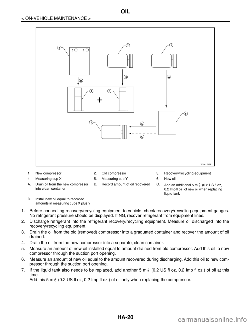
1. Before connecting recovery/recycling equipment to vehicle, check recovery/recycling equipment gauges.
No refrigerant pressure should be displayed. If NG, recover refrigerant from equipment lines.
2. Discharge refrigerant into the refrigerant recovery/recycling equipment. Measure oil discharged into the
recovery/recycling equipment.
3. Drain the oil from the old (removed) compressor into a graduated container and recover the amount of oil
drained.
4. Drain the oil from the new compressor into a separate, clean container.
5. Measure an amount of new oil installed equal to amount drained from old compressor. Add this oil to new
compressor through the suction port opening.
6. Measure an amount of new oil equal to the amount recovered during discharging. Add this oil to new com-
pressor through the suction port opening.
7. If the liquid tank also needs to be replaced, add another 5 m (0.2 US fl oz, 0.2 Imp fl oz.) of oil at this
time.
Add this 5 m (0.2 US fl oz, 0.2 Imp fl oz.) of oil only when replacing the compressor.
1. New compressor 2. Old compressor 3. Recovery/recycling equipment
4. Measuring cup X 5. Measuring cup Y 6. New oil
A. Drain oil from the new compressor
into clean containerB. Record amount of oil recovered C.
Add an additional 5 m (0.2 US fl oz,
0.2 Imp fl oz) of new oil when replacing
liquid tank
D. Install new oil equal to recorded
amounts in measuring cups X plus Y
WJIA1716E