2007 NISSAN TIIDA transmission
[x] Cancel search: transmissionPage 3238 of 5883
GI-44
< PRECAUTION >
PRECAUTIONS
General Precaution
INFOID:0000000001606118
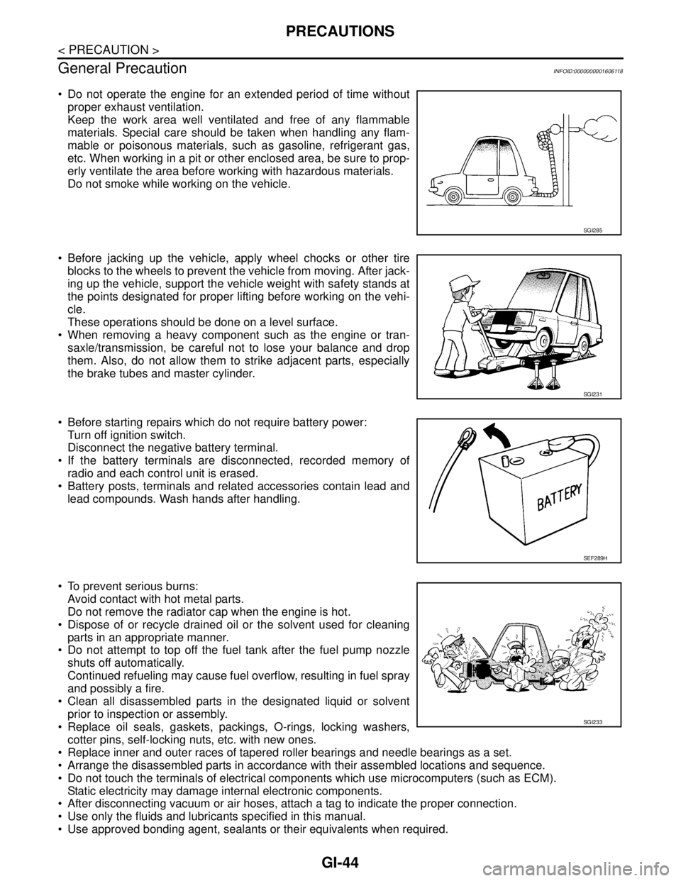
Do not operate the engine for an extended period of time without
proper exhaust ventilation.
Keep the work area well ventilated and free of any flammable
materials. Special care should be taken when handling any flam-
mable or poisonous materials, such as gasoline, refrigerant gas,
etc. When working in a pit or other enclosed area, be sure to prop-
erly ventilate the area before working with hazardous materials.
Do not smoke while working on the vehicle.
Before jacking up the vehicle, apply wheel chocks or other tire
blocks to the wheels to prevent the vehicle from moving. After jack-
ing up the vehicle, support the vehicle weight with safety stands at
the points designated for proper lifting before working on the vehi-
cle.
These operations should be done on a level surface.
When removing a heavy component such as the engine or tran-
saxle/transmission, be careful not to lose your balance and drop
them. Also, do not allow them to strike adjacent parts, especially
the brake tubes and master cylinder.
Before starting repairs which do not require battery power:
Turn off ignition switch.
Disconnect the negative battery terminal.
If the battery terminals are disconnected, recorded memory of
radio and each control unit is erased.
Battery posts, terminals and related accessories contain lead and
lead compounds. Wash hands after handling.
To prevent serious burns:
Avoid contact with hot metal parts.
Do not remove the radiator cap when the engine is hot.
Dispose of or recycle drained oil or the solvent used for cleaning
parts in an appropriate manner.
Do not attempt to top off the fuel tank after the fuel pump nozzle
shuts off automatically.
Continued refueling may cause fuel overflow, resulting in fuel spray
and possibly a fire.
Clean all disassembled parts in the designated liquid or solvent
prior to inspection or assembly.
Replace oil seals, gaskets, packings, O-rings, locking washers,
cotter pins, self-locking nuts, etc. with new ones.
Replace inner and outer races of tapered roller bearings and needle bearings as a set.
Arrange the disassembled parts in accordance with their assembled locations and sequence.
Do not touch the terminals of electrical components which use microcomputers (such as ECM).
Static electricity may damage internal electronic components.
After disconnecting vacuum or air hoses, attach a tag to indicate the proper connection.
Use only the fluids and lubricants specified in this manual.
Use approved bonding agent, sealants or their equivalents when required.
SGI285
SGI231
SEF289H
SGI233
Page 3239 of 5883
PRECAUTIONS
GI-45
< PRECAUTION >
C
D
E
F
G
H
I
J
K
L
MB
GI
N
O
P
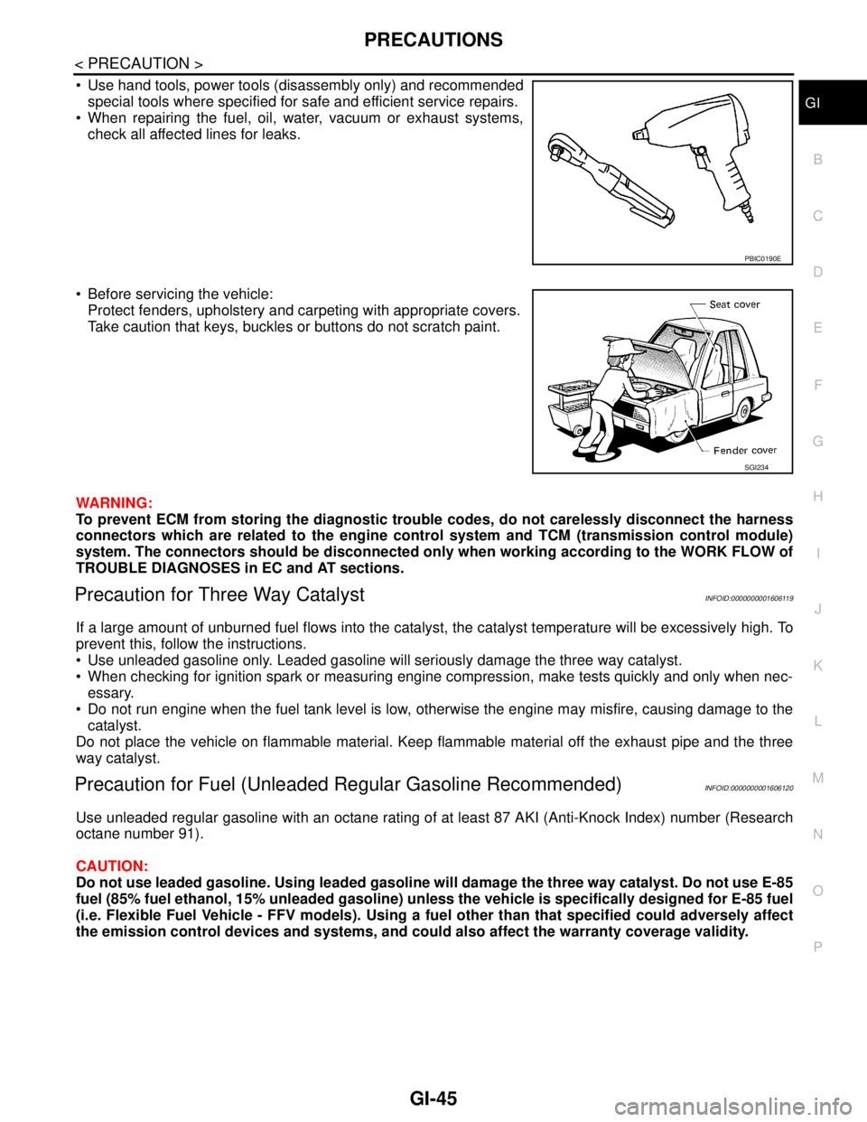
Use hand tools, power tools (disassembly only) and recommended
special tools where specified for safe and efficient service repairs.
When repairing the fuel, oil, water, vacuum or exhaust systems,
check all affected lines for leaks.
Before servicing the vehicle:
Protect fenders, upholstery and carpeting with appropriate covers.
Take caution that keys, buckles or buttons do not scratch paint.
WARNING:
To prevent ECM from storing the diagnostic trouble codes, do not carelessly disconnect the harness
connectors which are related to the engine control system and TCM (transmission control module)
system. The connectors should be disconnected only when working according to the WORK FLOW of
TROUBLE DIAGNOSES in EC and AT sections.
Precaution for Three Way CatalystINFOID:0000000001606119
If a large amount of unburned fuel flows into the catalyst, the catalyst temperature will be excessively high. To
prevent this, follow the instructions.
Use unleaded gasoline only. Leaded gasoline will seriously damage the three way catalyst.
When checking for ignition spark or measuring engine compression, make tests quickly and only when nec-
essary.
Do not run engine when the fuel tank level is low, otherwise the engine may misfire, causing damage to the
catalyst.
Do not place the vehicle on flammable material. Keep flammable material off the exhaust pipe and the three
way catalyst.
Precaution for Fuel (Unleaded Regular Gasoline Recommended)INFOID:0000000001606120
Use unleaded regular gasoline with an octane rating of at least 87 AKI (Anti-Knock Index) number (Research
octane number 91).
CAUTION:
Do not use leaded gasoline. Using leaded gasoline will damage the three way catalyst. Do not use E-85
fuel (85% fuel ethanol, 15% unleaded gasoline) unless the vehicle is specifically designed for E-85 fuel
(i.e. Flexible Fuel Vehicle - FFV models). Using a fuel other than that specified could adversely affect
the emission control devices and systems, and could also affect the warranty coverage validity.
PBIC0190E
SGI234
Page 3242 of 5883
GI-48
< PRECAUTION >
LIFTING POINT
LIFTING POINT
Special Service ToolINFOID:0000000001606131
CAUTION:
Every time the vehicle is lifted up, maintain the complete vehicle curb condition.
Since the vehicle's center of gravity changes when removing main parts on the front side (engine,
transmission, suspension etc.), support a jack up point on the rear side garage jack with a mission
jack or equivalent.
Since the vehicle's center of gravity changes when removing main parts on the rear side (rear axle,
suspension, etc.), support a jack up point on the front side garage jack with a mission jack or equiv-
alent.
Be careful not to smash or do not do anything that would affect piping parts.
Garage Jack and Safety Stand and 2-Pole LiftINFOID:0000000001606132
WARNING:
Park the vehicle on a level surface when using the jack. Make sure to avoid damaging pipes, tubes,
etc. under the vehicle.
Never get under the vehicle while it is supported only by the jack. Always use safety stands when
you have to get under the vehicle.
Place wheel chocks at both front and back of the wheels on the ground.
When lifting the vehicle, open the lift arms as wide as possible and ensure that the front and rear of
the vehicle are well balanced.
When setting the lift arm, do not allow the arm to contact the brake tubes, brake cable, fuel lines and
sill spoiler.
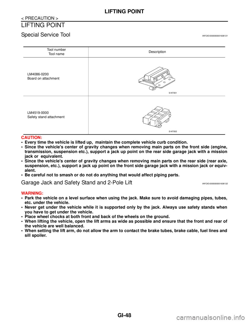
Tool number
Tool nameDescription
LM4086-0200
Board on attachment
LM4519-0000
Safety stand attachment
S-NT001
S-NT002
Page 3244 of 5883
GI-50
< PRECAUTION >
TOW TRUCK TOWING
TOW TRUCK TOWING
Tow Truck TowingINFOID:0000000001606140
CAUTION:
All applicable local laws regarding the towing operation must be obeyed.
It is necessary to use proper towing equipment to avoid possible damage to the vehicle during tow-
ing operation. Towing is in accordance with Towing Procedure Manual at dealer.
Always attach safety chains before towing.
When towing, make sure that the transmission, steering system and power train are in good order. If
any unit is damaged, dollies must be used.
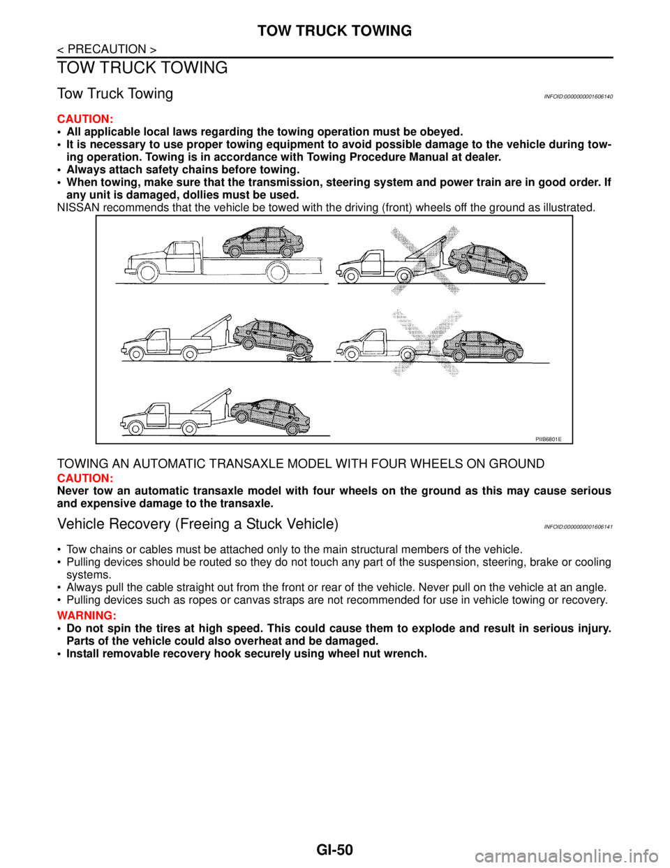
NISSAN recommends that the vehicle be towed with the driving (front) wheels off the ground as illustrated.
TOWING AN AUTOMATIC TRANSAXLE MODEL WITH FOUR WHEELS ON GROUND
CAUTION:
Never tow an automatic transaxle model with four wheels on the ground as this may cause serious
and expensive damage to the transaxle.
Vehicle Recovery (Freeing a Stuck Vehicle)INFOID:0000000001606141
Tow chains or cables must be attached only to the main structural members of the vehicle.
Pulling devices should be routed so they do not touch any part of the suspension, steering, brake or cooling
systems.
Always pull the cable straight out from the front or rear of the vehicle. Never pull on the vehicle at an angle.
Pulling devices such as ropes or canvas straps are not recommended for use in vehicle towing or recovery.
WARNING:
Do not spin the tires at high speed. This could cause them to explode and result in serious injury.
Parts of the vehicle could also overheat and be damaged.
Install removable recovery hook securely using wheel nut wrench.
PIIB6801E
Page 3245 of 5883
SERVICE INFORMATION FOR ELECTRICAL INCIDENT
GI-51
< BASIC INSPECTION >
C
D
E
F
G
H
I
J
K
L
MB
GI
N
O
PBASIC INSPECTION
SERVICE INFORMATION FOR ELECTRICAL INCIDENT
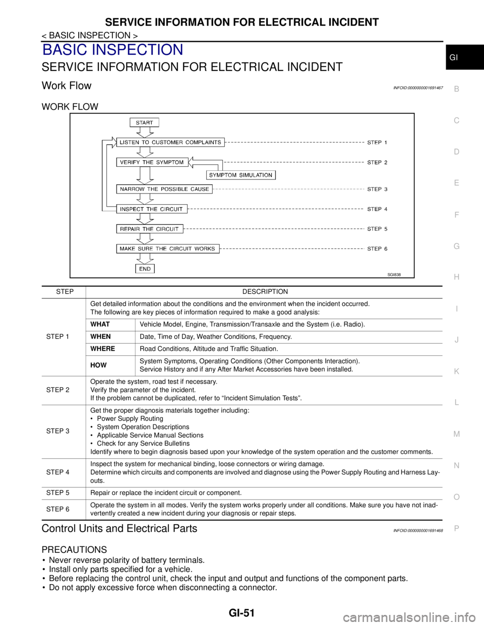
Work FlowINFOID:0000000001691467
WORK FLOW
Control Units and Electrical PartsINFOID:0000000001691468
PRECAUTIONS
Never reverse polarity of battery terminals.
Install only parts specified for a vehicle.
Before replacing the control unit, check the input and output and functions of the component parts.
Do not apply excessive force when disconnecting a connector.
SGI838
STEP DESCRIPTION
STEP 1Get detailed information about the conditions and the environment when the incident occurred.
The following are key pieces of information required to make a good analysis:
WHATVehicle Model, Engine, Transmission/Transaxle and the System (i.e. Radio).
WHENDate, Time of Day, Weather Conditions, Frequency.
WHERERoad Conditions, Altitude and Traffic Situation.
HOWSystem Symptoms, Operating Conditions (Other Components Interaction).
Service History and if any After Market Accessories have been installed.
STEP 2Operate the system, road test if necessary.
Verify the parameter of the incident.
If the problem cannot be duplicated, refer to “Incident Simulation Tests”.
STEP 3Get the proper diagnosis materials together including:
Power Supply Routing
System Operation Descriptions
Applicable Service Manual Sections
Check for any Service Bulletins
Identify where to begin diagnosis based upon your knowledge of the system operation and the customer comments.
STEP 4Inspect the system for mechanical binding, loose connectors or wiring damage.
Determine which circuits and components are involved and diagnose using the Power Supply Routing and Harness Lay-
outs.
STEP 5 Repair or replace the incident circuit or component.
STEP 6Operate the system in all modes. Verify the system works properly under all conditions. Make sure you have not inad-
vertently created a new incident during your diagnosis or repair steps.
Page 3257 of 5883
CONSULT-III CHECKING SYSTEM
GI-63
< BASIC INSPECTION >
C
D
E
F
G
H
I
J
K
L
MB
GI
N
O
PCONSULT-III CHECKING SYSTEM
DescriptionINFOID:0000000001691472
When CONSULT-III is connected with a data link connector
equipped on the vehicle side, it will communicate with the control
unit equipped in the vehicle and then enable various kinds of diag-
nostic tests.
Refer to “CONSULT-III Operation Manual” for more information.
Function and System ApplicationINFOID:0000000001728915
x: Applicable.1 : Hood release handle
2 : Data link connector
ALBIA0047ZZ
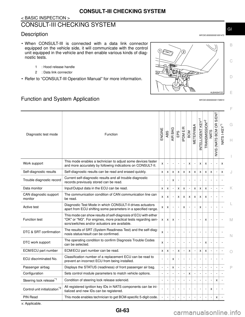
Diagnostic test mode Function
ENGINE
ABS
AIR BAG
EPS
IPDM E/R
BCM
METER/M&A
INTELLIGENT KEY*
1
TRANSMISSION*
2
NATS
NVIS (NATS BCM OR S/ENT
NATS I-KEY
*1
Work supportThis mode enables a technician to adjust some devices faster
and more accurately by following indications on CONSULT-II.x----x-xx--x
Self-diagnostic results Self-diagnostic results can be read and erased quickly. xxxxxxxxxx - x
Trouble diagnostic recordCurrent self-diagnostic results and all trouble diagnostic
records previously stored can be read.--x---------
Data monitor Input/Output data in the ECU can be read. x x - x x - x x x - - -
CAN diagnostic support
monitorThe communication condition of CAN communication line can
be read.xx - xxxxxx - - -
Active testDiagnostic Test Mode in which CONSULT-II drives actuators
apart from ECU shifting some parameters in a specified range.xx--x--x----
Function testThis mode can show results of self-diagnosis of ECU with either
"OK" or "NG". For engines, more practical tests regarding sen-
sors/switches and/or actuators are available.xxx-----x---
DTC & SRT confirmationThe results of SRT (System Readiness Test) and the self-diag-
nosis status/result can be confirmed.x-----------
DTC work supportThe operating condition to confirm Diagnosis Trouble Codes
can be selected.x-------x---
ECM/ECU part number ECM/ECU part number can be read. x x - x - x - x x - - -
ECU discriminated No.Classification number of a replacement ECU can be read to
prevent an incorrect ECU from being installed.--x---------
Passenger airbag Displays the STATUS (readiness) of front passenger air bag. --x---------
Configuration Sets control module parameters to match vehicle options. -----x------
Steering lock release
*1Condition of steering lock release solenoid. ----------x-
Control unit initialization
*3All registered ignition key IDs in NATS components can be ini-
tialized and new IDs can be registered.---------x--
PIN Read This mode enables technician to get BCM-specific 5-digit code.----------x-
Page 3258 of 5883

GI-64
< BASIC INSPECTION >
CONSULT-III CHECKING SYSTEM
*1: With Intelligent Key System.
*2: With automatic transmission.
*3: Without Intelligent Key System.
CONSULT-III Data Link Connector (DLC) CircuitINFOID:0000000001691474
INSPECTION PROCEDURE
If the CONSULT-III cannot diagnose the system properly, check the following items.
NOTE:
The CAN and DDL2 circuits from DLC pins 6, 7 and 14 may be connected to more than one system. A short in
any circuit connected to a control unit in one system may affect CONSULT-III access to other systems.
Symptom Check item
CONSULT-III cannot access
any system. CONSULT-III DLC power supply circuit (Terminal 8) and ground circuit (Terminal 4)
CONSULT-III cannot access in-
dividual system. (Other sys-
tems can be accessed.) Power supply and ground circuit for the control unit of the system (For detailed circuit, refer to wiring
diagram for each system.)
Open or short circuit between the system and CONSULT-III DLC (For detailed circuit, refer to wiring
diagram for each system.)
Open or short circuit CAN communication line. Refer to LAN-22, "
Trouble Diagnosis Flow Chart".
Page 3373 of 5883
![NISSAN TIIDA 2007 Service Repair Manual HAC-40
< COMPONENT DIAGNOSIS >[MANUAL AIR CONDITIONER]
PTC HEATER CONTROL SYSTEM
19.CHECK CIRCUIT CONTINUITY BETWEEN AMBIENT TEMPERATURE SENSOR AND PTC CONTROL
UNIT
Check continuity between ambient te NISSAN TIIDA 2007 Service Repair Manual HAC-40
< COMPONENT DIAGNOSIS >[MANUAL AIR CONDITIONER]
PTC HEATER CONTROL SYSTEM
19.CHECK CIRCUIT CONTINUITY BETWEEN AMBIENT TEMPERATURE SENSOR AND PTC CONTROL
UNIT
Check continuity between ambient te](/manual-img/5/57395/w960_57395-3372.png)
HAC-40
< COMPONENT DIAGNOSIS >[MANUAL AIR CONDITIONER]
PTC HEATER CONTROL SYSTEM
19.CHECK CIRCUIT CONTINUITY BETWEEN AMBIENT TEMPERATURE SENSOR AND PTC CONTROL
UNIT
Check continuity between ambient temperature sensor harness con-
nector M60 (A) terminal 3 and PTC control unit harness connector
M84 (B) terminal 8.
Is the inspection result normal
YES >> 1. If equipped with manual transmission, GO TO 20.
2. If equipped with automatic transmission, GO TO 22.
NO >> Repair harness or connector.
20.CHECK ENGINE RPM SIGNAL (MANUAL TRANSMISSION)
1. Reconnect PTC control unit.
2. Start the engine.
3. Check voltage between PTC control unit harness connector
M84 terminal 4 and ground.
Is the inspection result normal
YES >> GO TO 22.
NO >> GO TO 21.
21.CHECK CONTINUITY OF ENGINE RPM CIRCUIT BETWEEN FRONT AIR CONNTROL AND PTC CON-
TROL UNIT (MANUAL TRANSMISSION)
1. Turn ignition switch OFF.
2. Disconnect ECM and PTC control unit connector.
3. Check continuity between PTC control unit harness connector
M84 (A) terminal 4 and ECM harness connector F10 (B) termi-
nal 13.
4. Check continuity between PTC control unit harness connector
M84 (A) terminal 4 and ground.
Is the inspection result normal
YES >> Replace ECM. Refer to XX.
NO >> Repair harness or connector.
22.CHECK BCM INPUT (FAN ON) SIGNAL
AB
Continuity
Connector Terminal Connector Terminal
Ambient temperature
sensor: M643PTC control unit:
M848Yes
AWIIA0464ZZ
Te r m i n a l s
Vo l ta g e
(Approx.) (+) (−)
Connector Terminal
Ground
PTC control unit: M84 4 4.2V
SJIA0924E
AB
Continuity
Connector Terminal Connector Terminal
PTC control unit: M84 4 ECM: F10 13 Yes
A
GroundContinuity
Connector Terminal
PTC control unit: M84 4 No
SJIA0925E