Page 3175 of 5883

FUEL TANK
FL-15
< ON-VEHICLE REPAIR >
C
D
E
F
G
H
I
J
K
L
MA
FL
N
P O
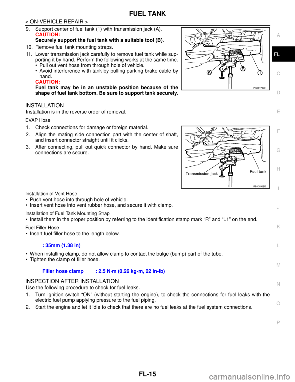
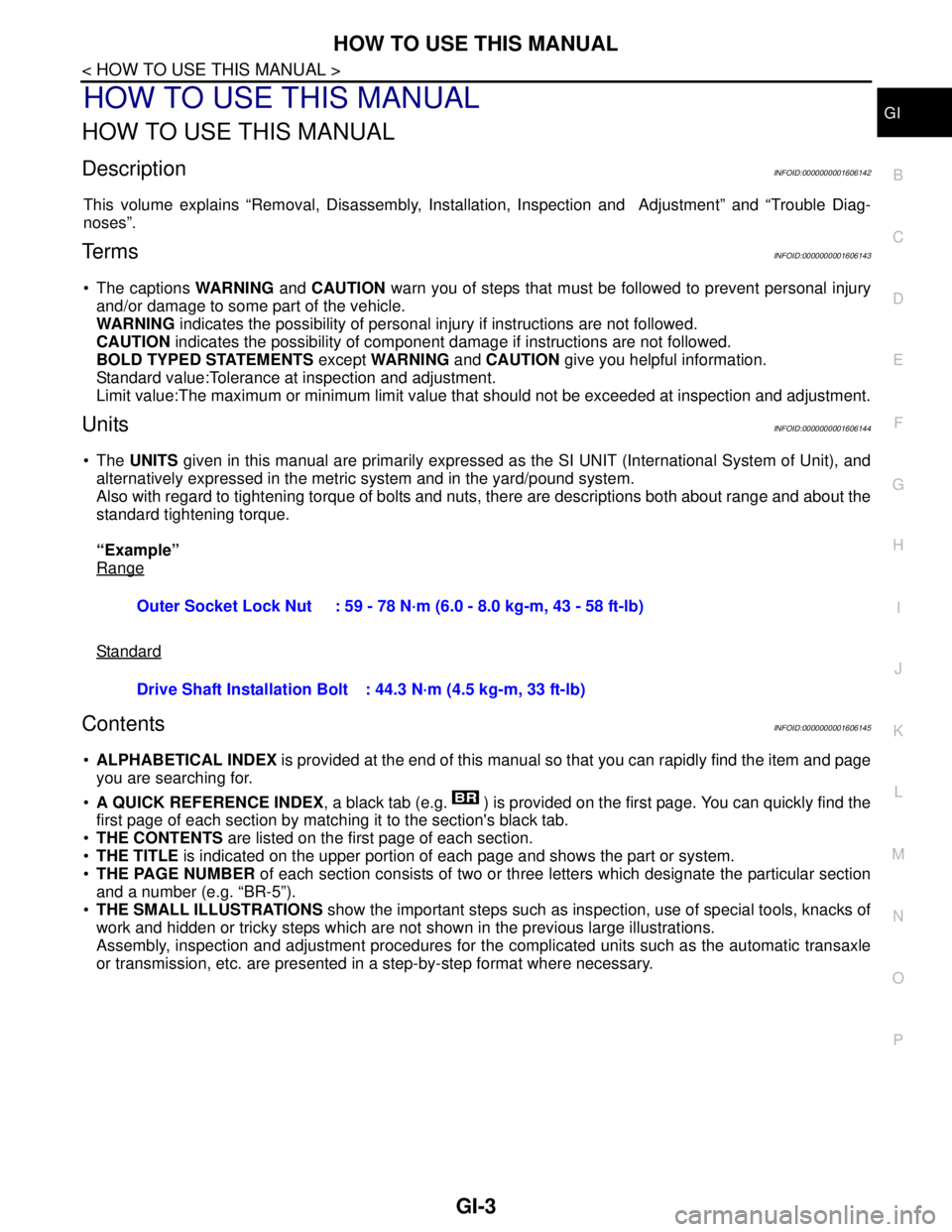
9. Support center of fuel tank (1) with transmission jack (A).
CAUTION:
Securely support the fuel tank with a suitable tool (B).
10. Remove fuel tank mounting straps.
11. Lower transmission jack carefully to remove fuel tank while sup-
porting it by hand. Perform the following works at the same time.
Pull out vent hose from through hole of vehicle.
Avoid interference with tank by pulling parking brake cable by
hand.
CAUTION:
Fuel tank may be in an unstable position because of the
shape of fuel tank bottom. Be sure to support tank securely.
INSTALLATION
Installation is in the reverse order of removal.
EVAP Hose
1. Check connections for damage or foreign material.
2. Align the mating side connection part with the center of shaft,
and insert connector straight until it clicks.
3. After connecting, pull out quick connector by hand. Make sure
connections are secure.
Installation of Vent Hose
Push vent hose into through hole of vehicle.
Insert vent hose into vent rubber hose, and secure it with clamp.
Installation of Fuel Tank Mounting Strap
Install them in the proper position by referring to the identification stamp mark “R” and “L1” on the end.
Fuel Filler Hose
Insert fuel filler hose to the length below.
When installing clamp, do not allow clamp to contact the bulge (bump) part of the tube.
Tighten the clamp of filler hose.
INSPECTION AFTER INSTALLATION
Use the following procedure to check for fuel leaks.
1. Turn ignition switch “ON” (without starting the engine), to check the connections for fuel leaks with the
electric fuel pump applying pressure to the fuel piping.
2. Start the engine and let it idle to check that there are no fuel leaks at the fuel system connections.
PBIC3792E
PBIC1508E
: 35mm (1.38 in)
Filler hose clamp : 2.5 N·m (0.26 kg-m, 22 in-lb)
Page 3197 of 5883

HOW TO USE THIS MANUAL
GI-3
< HOW TO USE THIS MANUAL >
C
D
E
F
G
H
I
J
K
L
MB
GI
N
O
PHOW TO USE THIS MANUAL
HOW TO USE THIS MANUAL
DescriptionINFOID:0000000001606142
This volume explains “Removal, Disassembly, Installation, Inspection and Adjustment” and “Trouble Diag-
noses”.
Te r m sINFOID:0000000001606143
The captions WARNING and CAUTION warn you of steps that must be followed to prevent personal injury
and/or damage to some part of the vehicle.
WARNING indicates the possibility of personal injury if instructions are not followed.
CAUTION indicates the possibility of component damage if instructions are not followed.
BOLD TYPED STATEMENTS except WARNING and CAUTION give you helpful information.
Standard value:Tolerance at inspection and adjustment.
Limit value:The maximum or minimum limit value that should not be exceeded at inspection and adjustment.
UnitsINFOID:0000000001606144
The UNITS given in this manual are primarily expressed as the SI UNIT (International System of Unit), and
alternatively expressed in the metric system and in the yard/pound system.
Also with regard to tightening torque of bolts and nuts, there are descriptions both about range and about the
standard tightening torque.
“Example”
Range
Standard
ContentsINFOID:0000000001606145
ALPHABETICAL INDEX is provided at the end of this manual so that you can rapidly find the item and page
you are searching for.
A QUICK REFERENCE INDEX, a black tab (e.g. ) is provided on the first page. You can quickly find the
first page of each section by matching it to the section's black tab.
THE CONTENTS are listed on the first page of each section.
THE TITLE is indicated on the upper portion of each page and shows the part or system.
THE PAGE NUMBER of each section consists of two or three letters which designate the particular section
and a number (e.g. “BR-5”).
THE SMALL ILLUSTRATIONS show the important steps such as inspection, use of special tools, knacks of
work and hidden or tricky steps which are not shown in the previous large illustrations.
Assembly, inspection and adjustment procedures for the complicated units such as the automatic transaxle
or transmission, etc. are presented in a step-by-step format where necessary. Outer Socket Lock Nut : 59 - 78 N·m (6.0 - 8.0 kg-m, 43 - 58 ft-lb)
Drive Shaft Installation Bolt: 44.3 N·m (4.5 kg-m, 33 ft-lb)
Page 3210 of 5883
GI-16
< HOW TO USE THIS MANUAL >
HOW TO USE THIS MANUAL
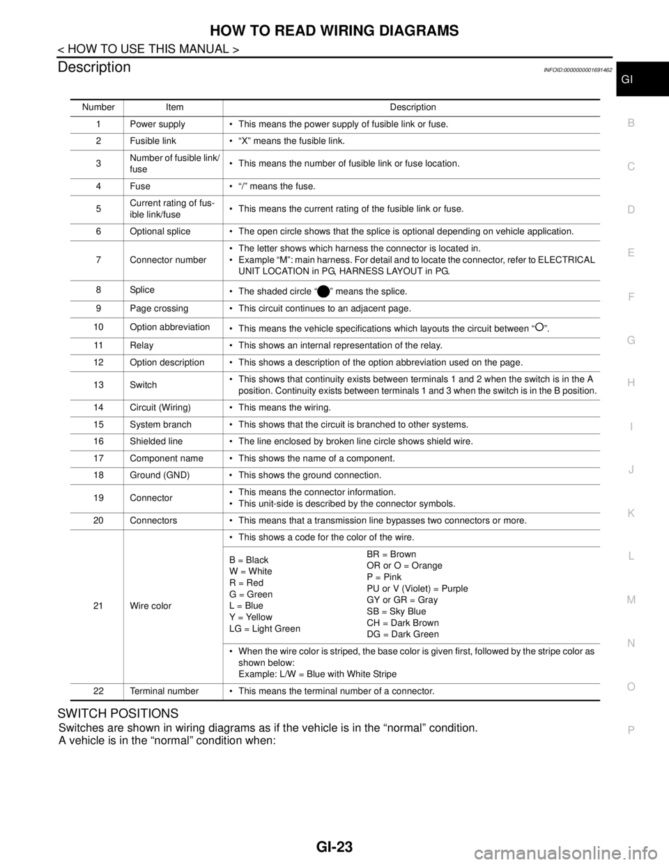
The Reference Area of the wiring diagram contains references to additional electrical reference pages at the
end of the manual. If connector numbers and titles are shown in the Reference Area of the wiring diagram,
these connector symbols are not shown in the Connector Area.
AbbreviationsINFOID:0000000001606150
The following ABBREVIATIONS are used:
SGI092A
ABBREVIATION DESCRIPTION
A/C Air Conditioner
A/T Automatic Transaxle/Transmission
ATF Automatic Transmission Fluid
CVT Continuously Variable Transmission
D
1Drive range 1st gear
D
2Drive range 2nd gear
D
3Drive range 3rd gear
D
4Drive range 4th gear
Page 3211 of 5883
HOW TO USE THIS MANUAL
GI-17
< HOW TO USE THIS MANUAL >
C
D
E
F
G
H
I
J
K
L
MB
GI
N
O
PFR, RR Front, Rear
LH, RH Left-Hand, Right-Hand
M/T Manual Transaxle/Transmission
OD Overdrive
P/S Power Steering
SAE Society of Automotive Engineers, Inc.
SDS Service Data and Specifications
SST Special Service Tools
2WD 2-Wheel Drive
2
22nd range 2nd gear
2
12nd range 1st gear
1
21st range 2nd gear
1
11st range 1st gear ABBREVIATION DESCRIPTION
Page 3217 of 5883

HOW TO READ WIRING DIAGRAMS
GI-23
< HOW TO USE THIS MANUAL >
C
D
E
F
G
H
I
J
K
L
MB
GI
N
O
P
DescriptionINFOID:0000000001691462
SWITCH POSITIONS
Switches are shown in wiring diagrams as if the vehicle is in the “normal” condition.
A vehicle is in the “normal” condition when:
Number Item Description
1 Power supply This means the power supply of fusible link or fuse.
2 Fusible link “X” means the fusible link.
3Number of fusible link/
fuse This means the number of fusible link or fuse location.
4 Fuse “/” means the fuse.
5Current rating of fus-
ible link/fuse This means the current rating of the fusible link or fuse.
6 Optional splice The open circle shows that the splice is optional depending on vehicle application.
7 Connector number The letter shows which harness the connector is located in.
Example “M”: main harness. For detail and to locate the connector, refer to ELECTRICAL
UNIT LOCATION in PG, HARNESS LAYOUT in PG.
8Splice
The shaded circle “ ” means the splice.
9 Page crossing This circuit continues to an adjacent page.
10 Option abbreviation
This means the vehicle specifications which layouts the circuit between “ ”.
11 Relay This shows an internal representation of the relay.
12 Option description This shows a description of the option abbreviation used on the page.
13 Switch This shows that continuity exists between terminals 1 and 2 when the switch is in the A
position. Continuity exists between terminals 1 and 3 when the switch is in the B position.
14 Circuit (Wiring) This means the wiring.
15 System branch This shows that the circuit is branched to other systems.
16 Shielded line The line enclosed by broken line circle shows shield wire.
17 Component name This shows the name of a component.
18 Ground (GND) This shows the ground connection.
19 Connector This means the connector information.
This unit-side is described by the connector symbols.
20 Connectors This means that a transmission line bypasses two connectors or more.
21 Wire color This shows a code for the color of the wire.
B = Black
W = White
R = Red
G = Green
L = Blue
Y = Yellow
LG = Light GreenBR = Brown
OR or O = Orange
P = Pink
PU or V (Violet) = Purple
GY or GR = Gray
SB = Sky Blue
CH = Dark Brown
DG = Dark Green
When the wire color is striped, the base color is given first, followed by the stripe color as
shown below:
Example: L/W = Blue with White Stripe
22 Terminal number This means the terminal number of a connector.
Page 3219 of 5883
ABBREVIATIONS
GI-25
< HOW TO USE THIS MANUAL >
C
D
E
F
G
H
I
J
K
L
MB
GI
N
O
PABBREVIATIONS
Abbreviation ListINFOID:0000000001691463
The following ABBREVIATIONS are used:
ABBREVIATION DESCRIPTION
A/C Air Conditioner
A/T Automatic Transaxle/Transmission
ATF Automatic Transmission Fluid
AWD All wheel drive
D
1Drive range 1st gear
D
2Drive range 2nd gear
D
3Drive range 3rd gear
D
4Drive range 4th gear
FR, RR Front, Rear
LH, RH Left-Hand, Right-Hand
OD Overdrive
P/S Power Steering
SAE Society of Automotive Engineers, Inc.
SDS Service Data and Specifications
SST Special Service Tools
2WD 2-Wheel Drive
2
22nd range 2nd gear
2
12nd range 1st gear
1
21st range 2nd gear
1
11st range 1st gear
Page 3221 of 5883

RECOMMENDED CHEMICAL PRODUCTS AND SEALANTS
GI-27
< HOW TO USE THIS MANUAL >
C
D
E
F
G
H
I
J
K
L
MB
GI
N
O
PRECOMMENDED CHEMICAL PRODUCTS AND SEALANTS
Recommended Chemical Products and SealantsINFOID:0000000001691465
Refer to the following chart for help in selecting the appropriate chemical product or sealant.
Product Description PurposeNissan North America
Part No. (USA)Nissan Canada Part
No. (Canada)Aftermarket Cross-
reference Part Nos.
1Rear View Mirror Adhe-
siveUsed to permanently re-
mount rear view mirrors to
windows.999MP-AM000P 99998-50505 Permatex 81844
2Anaerobic Liquid Gas-
ketFor metal-to-metal flange
sealing.
Can fill a 0.38 mm (0.015
inch) gap and provide in-
stant sealing for most pow-
ertrain applications.999MP-AM001P 99998-50503Permatex 51813 and
51817
3High Performance
Thread SealantProvides instant sealing on
any threaded straight or
parallel threaded fitting.
(Thread sealant only, no
locking ability.)
Do not use on plastic.999MP-AM002P 999MP-AM002P Permatex 56521
4 Silicone RTVGasket Maker999MP-AM003P
(Ultra Grey)99998-50506
(Ultra Grey)Permatex Ultra Grey
82194;
Three Bond
1207,1215, 1216,
1217F, 1217G and
1217H
Nissan RTV Part No.
999MP-A7007
Gasket Maker for Maxima/
Quest 5-speed automatic
transmission
(RE5F22A)––Three Bond 1281B
or exact equivalent in
its quality
5High Temperature,
High Strength Thread
Locking Sealant (Red)Threadlocker 999MP-AM004P 999MP-AM004PPermatex 27200;
Three Bond 1360,
1360N, 1305 N&P,
1307N, 1335,
1335B, 1363B,
1377C, 1386B, D&E
and 1388
Loctite 648
6Medium Strength
Thread Locking Seal-
ant (Blue)Threadlocker (service tool
removable)999MP-AM005P 999MP-AM005PPermatex 24200,
24206, 24240,
24283 and 09178;
Three Bond 1322,
1322N, 1324 D&N,
1333D, 1361C,
1364D, 1370C and
1374
Page 3225 of 5883
TERMINOLOGY
GI-31
< HOW TO USE THIS MANUAL >
C
D
E
F
G
H
I
J
K
L
MB
GI
N
O
P
***: Not applicableTransmission control module TCM A/T control unit
Turbocharger TC Turbocharger
Vehicle speed sensor VSS Vehicle speed sensor
Volume air flow sensor VAFS Air flow meter
Warm up oxidation catalyst WU-OC Catalyst
Warm up oxidation catalytic converter sys-
temWU-OC system ***
Warm up three way catalyst WU-TWC Catalyst
Warm up three way catalytic converter sys-
temWU-TWC system ***
Wide open throttle position switch WOTP switch Full switchNEW TERMNEW ACRONYM /
ABBREVIATIONOLD TERM