Page 57 of 172
 - DAYTIME LIGHT SYSTEM -
LT-57
C
D
E
F
G
H
I
J
L
MA
B
LT
Revision: 2006 November2007 350Z
5. CHECK HEADLAMP CIRCUIT
1. Turn ignition switch OFF.
2. Disconnect IPDM E/R connector")
HEADLAMP (FOR CANADA) - DAYTIME LIGHT SYSTEM -
LT-57
C
D
E
F
G
H
I
J
L
MA
B
LT
Revision: 2006 November2007 350Z
5. CHECK HEADLAMP CIRCUIT
1. Turn ignition switch OFF.
2. Disconnect IPDM E/R connector.
3. Check continuity between IPDM E/R harness connector and
front combination lamp (RH and LH) harness connector.
OK or NG
OK >> Replace IPDM E/R.
NG >> Repair harness or connector.
6. CHECK HEADLAMP GROUND
1. Turn ignition switch OFF.
2. Check continuity between front combination lamp (RH and LH)
harness connector and ground.
OK or NG
OK >> Check headlamp harness and connectors, ballasts (HID
control unit), and xenon bulbs. Refer to LT- 6 0 , "
Xenon
Headlamp Trouble Diagnosis" .
NG >> Repair harness or connector.
Headlamp Low Beam Does Not Illuminate (One Side)NKS004XT
1. CHECK BULB
Check ballast (HID control unit) and xenon bulb of lamp which does not illuminate. Refer to LT- 6 0 , "
Xenon
Headlamp Trouble Diagnosis" .
OK or NG
OK >> GO TO 2.
NG >> Replace malfunctioning part.
Te r m i n a l s
Continuity IPDM E/R Front combination lamp
Connector Terminal Connector Terminal
RH
E720 E24 7
Ye s
LH 30 E40 7
SKIA8670E
Front combination lamp
connectorTe r m i n a l
Ground Continuity
RH E24 4
Ye s
LH E40 4
PKIA4907E
Page 58 of 172
 - DAYTIME LIGHT SYSTEM -
Revision: 2006 November2007 350Z
2. CHECK HEADLAMP INPUT SIGNAL
1. Turn ignition switch OFF.
2. Disconnect front combination lamp RH or LH connect")
LT-58
HEADLAMP (FOR CANADA) - DAYTIME LIGHT SYSTEM -
Revision: 2006 November2007 350Z
2. CHECK HEADLAMP INPUT SIGNAL
1. Turn ignition switch OFF.
2. Disconnect front combination lamp RH or LH connector.
3. Turn ignition switch ON.
4. Lighting switch is turned 2ND position.
5. Check voltage between front combination lamp RH or LH har-
ness connector and ground.
OK or NG
OK >> GO TO 4.
NG >> GO TO 3.
3. CHECK HEADLAMP CIRCUIT
1. Turn ignition switch OFF.
2. Disconnect IPDM E/R connector.
3. Check continuity between IPDM E/R harness connector and
front combination lamp RH or LH harness connector.
OK or NG
OK >> Replace IPDM E/R.
NG >> Repair harness or connector.
4. CHECK HEADLAMP GROUND
Check continuity between front combination lamp RH or LH harness
connector and ground.
OK or NG
OK >> Check headlamp harness and connector.
NG >> Repair harness or connector.
Terminals
Voltage
(Approx.) (+)
(-)
Front combination lamp
connectorTerminal
RH E24 7
Ground Battery voltage
LH E40 7
PKIA7010E
Terminals
Continuity IPDM E/R Front combination lamp
Connector Terminal Connector Terminal
RH
E720 E24 7
Ye s
LH 30 E40 7
SKIA8670E
Front combination lamp
connectorTerminal
Ground Continuity
RH E24 4
Ye s
LH E40 4
PKIA4907E
Page 59 of 172
 - DAYTIME LIGHT SYSTEM -
LT-59
C
D
E
F
G
H
I
J
L
MA
B
LT
Revision: 2006 November2007 350Z
Headlamps Does Not Turn OFFNKS004XU
1. CHECK HEADLAMP TURN OFF
Make sure that lighting s")
HEADLAMP (FOR CANADA) - DAYTIME LIGHT SYSTEM -
LT-59
C
D
E
F
G
H
I
J
L
MA
B
LT
Revision: 2006 November2007 350Z
Headlamps Does Not Turn OFFNKS004XU
1. CHECK HEADLAMP TURN OFF
Make sure that lighting switch is OFF. And check if headlamp turns off when ignition switch is turned OFF.
OK or NG
OK >> GO TO 3.
NG >> GO TO 2.
2. CHECK COMBINATION SWITCH INPUT SIGNAL
CONSULT-III DATA MONITOR
1. Select "HEAD LAMP1" and "HEAD LAMP2" of BCM data monitor item.
2. With operating the lighting switch, check the monitor status.
OK or NG
OK >> Replace IPDM E/R. Refer to PG-26, "Removal and Installation of IPDM E/R" .
NG >> Check combination switch (lighting switch). Refer to LT- 9 2 , "
Combination Switch Inspection" .
3. CHECKING CAN COMMUNICATIONS BETWEEN BCM AND IPDM E/R
Perform self-diagnosis for “BCM” with CONSULT-III.
Display of self-diagnosis results
NO DTC>> Replace IPDM E/R. Refer to PG-26, "Removal and Installation of IPDM E/R" .
CAN COMM CIRCUIT>> Refer to BCS-16, "
CAN Communication Inspection Using CONSULT-III (Self-Diag-
nosis)" .
General Information for Xenon Headlamp Trouble DiagnosisNKS004XV
In most cases, malfunction of xenon headlamp - “does not illuminate”, “flickers” or “dark” - is caused by a mal-
functioning xenon bulb. A malfunctioning HID control unit or lamp housing, however, may be a cause. Be sure
to perform trouble diagnosis following the steps described below.
Caution:NKS004XW
�Installation or removal of connector must be done with lighting switch OFF.
�Disconnect the battery cable from the negative terminal or remove power fuse.
CAUTION:
After the battery cables are disconnected, never open/close the driver and/or front passenger door
with the window in the full up position. The automatic window adjusting function will not work and
the side roof panel may be damaged.
�When the lamp is illuminated (when lighting switch is ON), never touch harness, HID control unit, inside of
lamp, or lamp metal parts.
�To check illumination, temporarily install lamp in vehicle. Be sure to connect power at vehicle side connec-
tor.
�If error can be traced directly to electrical system, first check for items such as blown fuses and fusible
links, broken wires or loose connectors, dislocated terminals, and improper connections.
�Never work with wet hands.
�Using a tester for HID control unit circuit trouble diagnosis is prohibited.
�Disassembling HID control unit or harnesses (bulb socket harness, ECM harness) is prohibited.
�Immediately after illumination, light intensity and color will fluctuate, but there is nothing wrong.
�When bulb has come to end of its life, brightness will drop significantly, it will flash repeatedly, or light color
will turn reddish.When lighting switch is OFF : HEAD LAMP SW1 OFF
: HEAD LAMP SW2 OFF
Page 60 of 172
 - DAYTIME LIGHT SYSTEM -
Revision: 2006 November2007 350Z
Xenon Headlamp Trouble DiagnosisNKS004XX
1. CHECK 1: XENON HEADLAMP LIGHTING
Install normal xenon bulb to correspo")
LT-60
HEADLAMP (FOR CANADA) - DAYTIME LIGHT SYSTEM -
Revision: 2006 November2007 350Z
Xenon Headlamp Trouble DiagnosisNKS004XX
1. CHECK 1: XENON HEADLAMP LIGHTING
Install normal xenon bulb to corresponding xenon bulb headlamp, and check if lamp lights up.
OK or NG
OK >> Replace xenon bulb.
NG >> GO TO 2.
2. CHECK 2: XENON HEADLAMP LIGHTING
Install normal HID control unit to corresponding xenon headlamp, and check if lamp lights up.
OK or NG
OK >> Replace HID control unit.
NG >> GO TO 3.
3. CHECK 3: XENON HEADLAMP LIGHTING
Install normal xenon lamp housing assembly to corresponding xenon headlamp, and check if lamp lights up.
OK or NG
OK >> Replace xenon headlamp housing assembly. [Malfunction in starter (boosting circuit) in xenon
headlamp housing]
NG >> INSPECTION END
Aiming AdjustmentNKS004XY
PREPARATION BEFORE ADJUSTING
For details, refer to the regulations in your own country.
Before performing aiming adjustment, check the following.
1. Keep all tires inflated to correct pressures.
2. Place vehicle on level surface.
PKIC4917E
Page 61 of 172
 - DAYTIME LIGHT SYSTEM -
LT-61
C
D
E
F
G
H
I
J
L
MA
B
LT
Revision: 2006 November2007 350Z
3. Set that there is no-load in vehicle other than the driver (or equivalent weight plac")
HEADLAMP (FOR CANADA) - DAYTIME LIGHT SYSTEM -
LT-61
C
D
E
F
G
H
I
J
L
MA
B
LT
Revision: 2006 November2007 350Z
3. Set that there is no-load in vehicle other than the driver (or equivalent weight placed in driver's position).
Coolant, engine oil filled up to correct level and full fuel tank.
LOW BEAM AND HIGH BEAM
1. Turn headlamp low beam ON.
2. Use adjusting screws to perform aiming adjustment.
ADJUSTMENT USING AN ADJUSTMENT SCREEN (LIGHT/DARK BORDERLINE)
If the vehicle front body has been repaired and/or the headlamp assembly has been replaced, check aiming.
Use the aiming chart shown in the figure.
�Basic illumination area for adjustment should be within the range shown on the aiming chart.
Adjust headlamp accordingly.
Bulb ReplacementNKS004XZ
HEADLAMP HIGH/LOW BEAM
1. Turn lighting switch OFF.
2. Open the driver and front passenger window, and then discon-
nect the battery cable from the negative terminal or remove
power fuse.
CAUTION:
After the battery cables are disconnected, never open/close
the driver and/or front passenger door with the window in
the full up position. The automatic window adjusting func-
tion will not work and the side roof panel may be damaged.
3. Remove headlamp. Refer to LT- 6 2 , "
Removal and Installation" .
4. Turn plastic cap counterclockwise and unlock it.
5. Turn bulb socket counterclockwise and unlock it.
6. Unlock retaining spring and remove bulb from headlamp.
7. Installation is the reverse order of removal.
PKIB5186E
PKIC4918E
Page 62 of 172
 - DAYTIME LIGHT SYSTEM -
Revision: 2006 November2007 350Z
NOTE:
After installation, perform aiming adjustment. Refer to LT- 6 0 , \"
Aiming Adjustment\" .
PARKING LAMP
1. Tu")
LT-62
HEADLAMP (FOR CANADA) - DAYTIME LIGHT SYSTEM -
Revision: 2006 November2007 350Z
NOTE:
After installation, perform aiming adjustment. Refer to LT- 6 0 , "
Aiming Adjustment" .
PARKING LAMP
1. Turn lighting switch OFF.
2. Remove fender protector (front). Refer to EI-21, "
FENDER PROTECTOR" .
3. Turn bulb socket counterclockwise and unlock it.
4. Remove bulb from its socket.
5. Installation is the reverse order of removal.
FRONT TURN SIGNAL LAMP
1. Turn lighting switch OFF.
2. Remove fender protector (front). Refer to EI-21, "
FENDER PROTECTOR" .
3. Turn bulb socket counterclockwise and unlock it.
4. Remove bulb from its socket.
5. Installation is the reverse order of removal.
FRONT SIDE MARKER LAMP
1. Remove headlamp. Refer to LT- 6 2 , "Removal and Installation" .
2. Replacement integral with headlamp housing assembly.
3. Installation is reverse order of removal.
CAUTION:
After installing bulb, be sure to install plastic cap and bulb socket securely to insure watertightness.
Removal and InstallationNKS004Y0
REMOVAL
1. Open the driver and front passenger window, and then disconnect the battery cable from the negative ter-
minal or remove power fuse.
CAUTION:
After the battery cables are disconnected, never open/close the driver and/or front passenger door
with the window in the full up position. The automatic window adjusting function will not work and
the side roof panel may be damaged.
2. Remove front bumper fascia. Refer to EI-14, "
FRONT
BUMPER" .
3. Remove headlamp mounting bolts.
4. Pull head lamp toward vehicle front, disconnect connector, and
remove headlamp.
INSTALLATION
Installation is the reverse order of removal.
NOTE:
After installation, perform aiming adjustment. Refer to LT- 6 0 , "
Aiming Adjustment" . Headlamp high/low beam (Xenon) : 12V - 35W (D2R)
Parking lamp : 12V - 5W
Front turn signal lamp/— : 12V - 28/8W (amber)
Front side marker lamp : LED
PKIA1865E
Headlamp mounting bolt : 6.1N·m (0.62 kg-m, 54 in lb)
Page 63 of 172
 - DAYTIME LIGHT SYSTEM -
LT-63
C
D
E
F
G
H
I
J
L
MA
B
LT
Revision: 2006 November2007 350Z
Disassembly and Assembly NKS004Y1
DISASSEMBLY
1. Turn plastic cap counterclockwise, and")
HEADLAMP (FOR CANADA) - DAYTIME LIGHT SYSTEM -
LT-63
C
D
E
F
G
H
I
J
L
MA
B
LT
Revision: 2006 November2007 350Z
Disassembly and Assembly NKS004Y1
DISASSEMBLY
1. Turn plastic cap counterclockwise, and unlock it.
2. Turn xenon bulb socket counterclockwise, and unlock it.
3. Unlock retaining spring, and remove xenon bulb.
4. Disconnect xenon bulb socket ground.
5. Remove HID control unit mounting screws.
6. Remove ground screw from HID control unit.
7. Disconnect connectors from HID control unit.
8. Pull out xenon bulb socket from head lamp housing assembly.
9. Turn parking lamp bulb socket counterclockwise and unlock it.
10. Remove parking lamp bulb from its socket.
11. Turn front turn signal lamp bulb socket counterclockwise and unlock it.
12. Remove front turn signal lamp bulb from its socket.
SKIB7543E
1. Retaining spring 2. Xenon bulb socket ground 3. Front turn signal lamp bulb
4. Front turn signal lamp bulb socket 5. Xenon bulb 6. Xenon bulb socket
7. Parking lamp bulb 8. Parking lamp bulb socket 9. Seal packing
10. Plastic cap 11. Ground screw 12. Seal packing
13. HID control unit 14. HID control unit mounting screw 15. Headlamp housing assembly
:N·m (kg-m, in-lb)
: Always replace after every disassembly.
Page 64 of 172
LT-64
HEADLAMP (FOR CANADA) - DAYTIME LIGHT SYSTEM -
Revision: 2006 November2007 350Z
ASSEMBLY
Assembly is the reverse order of disassembly.
CAUTION:
�When HID control unit is removed, reinstall it securely and avoid any looseness.
�After installing bulb, be sure to install plastic cap and bulb socket securely to insure watertight-
ness
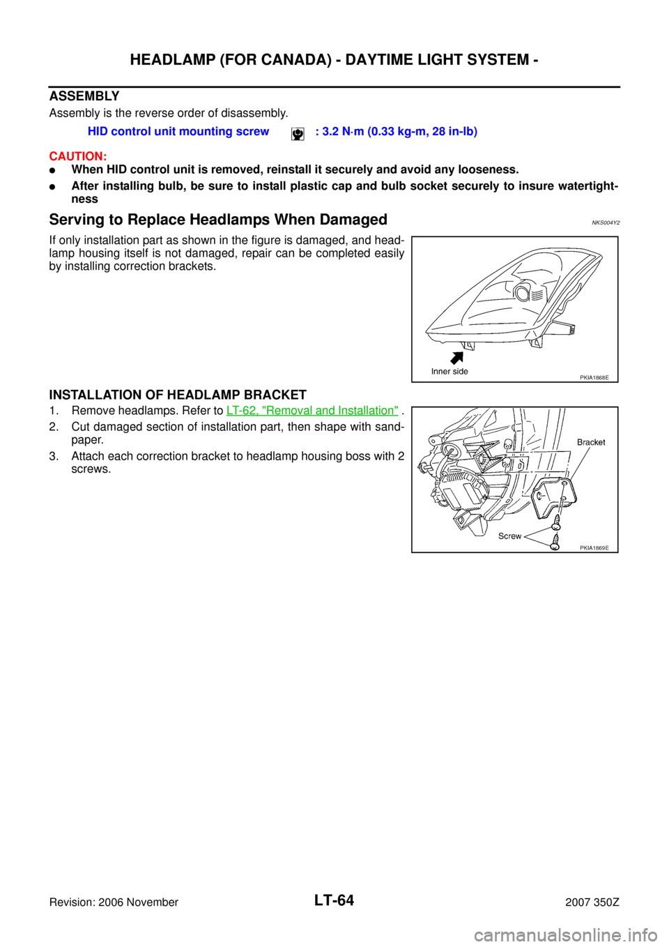
Serving to Replace Headlamps When DamagedNKS004Y2
If only installation part as shown in the figure is damaged, and head-
lamp housing itself is not damaged, repair can be completed easily
by installing correction brackets.
INSTALLATION OF HEADLAMP BRACKET
1. Remove headlamps. Refer to LT- 6 2 , "Removal and Installation" .
2. Cut damaged section of installation part, then shape with sand-
paper.
3. Attach each correction bracket to headlamp housing boss with 2
screws.HID control unit mounting screw : 3.2 N·m (0.33 kg-m, 28 in-lb)
PKIA1868E
PKIA1869E
 1
1 2
2 3
3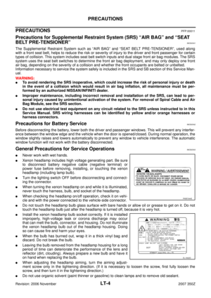 4
4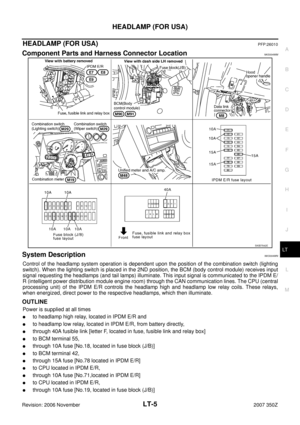 5
5 6
6 7
7 8
8 9
9 10
10 11
11 12
12 13
13 14
14 15
15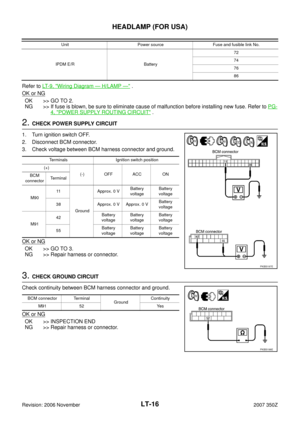 16
16 17
17 18
18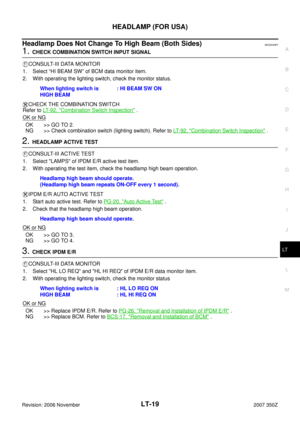 19
19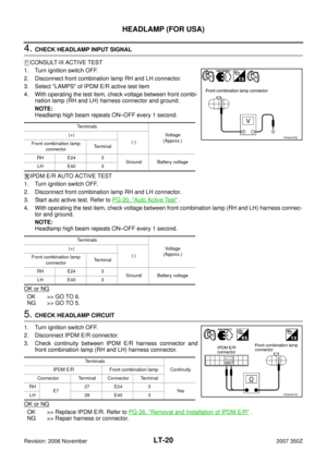 20
20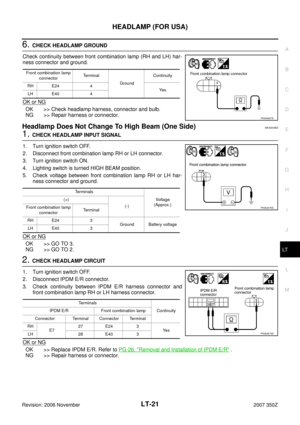 21
21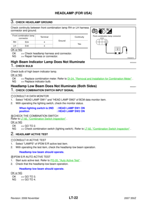 22
22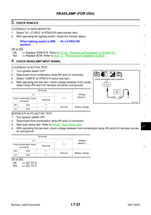 23
23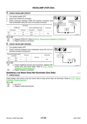 24
24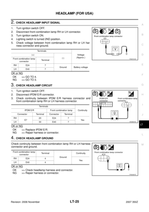 25
25 26
26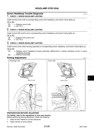 27
27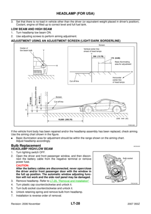 28
28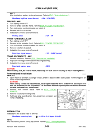 29
29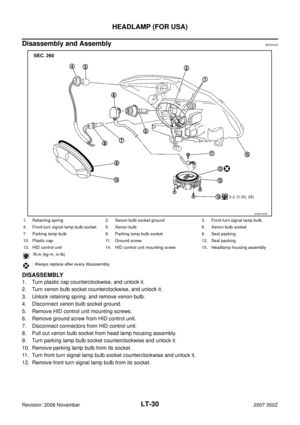 30
30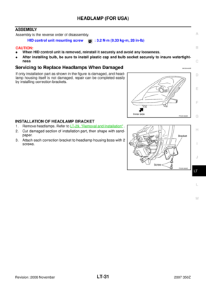 31
31 32
32 33
33 34
34 35
35 36
36 37
37 38
38 39
39 40
40 41
41 42
42 43
43 44
44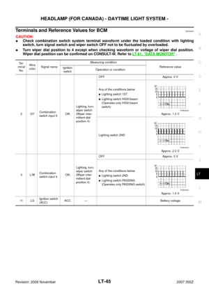 45
45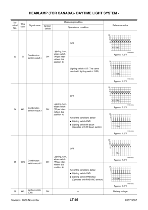 46
46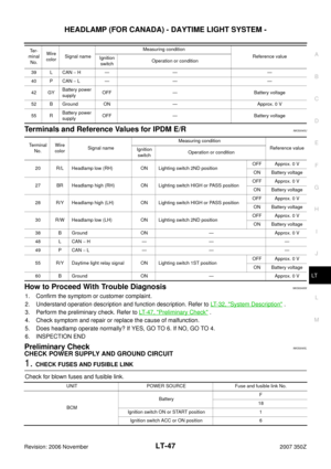 47
47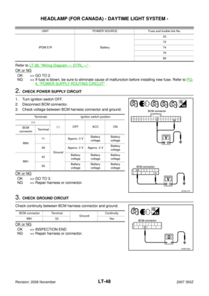 48
48 49
49 50
50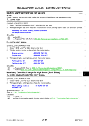 51
51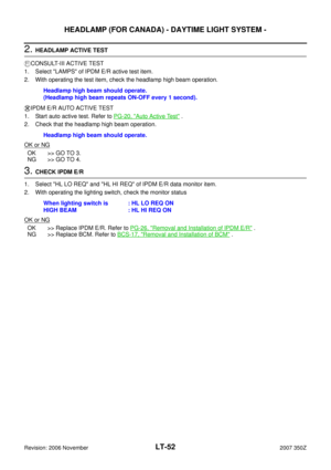 52
52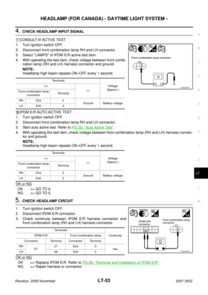 53
53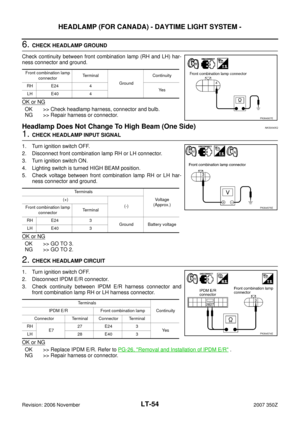 54
54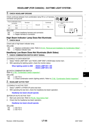 55
55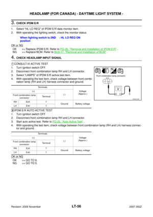 56
56 57
57 58
58 59
59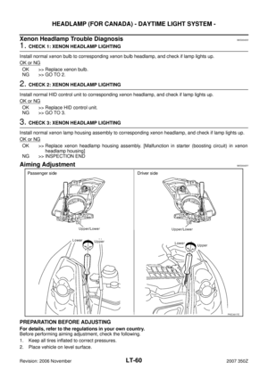 60
60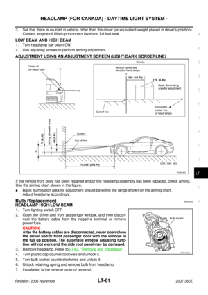 61
61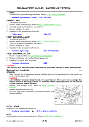 62
62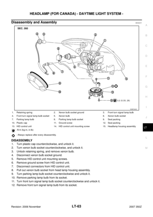 63
63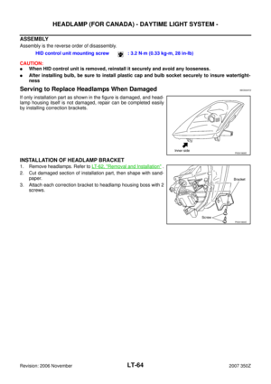 64
64 65
65 66
66 67
67 68
68 69
69 70
70 71
71 72
72 73
73 74
74 75
75 76
76 77
77 78
78 79
79 80
80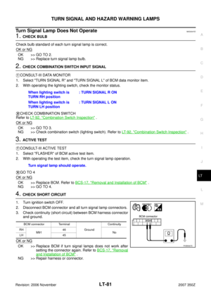 81
81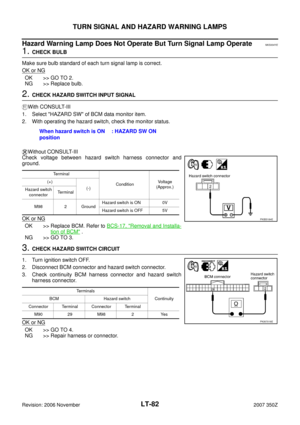 82
82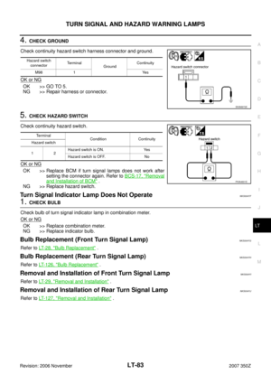 83
83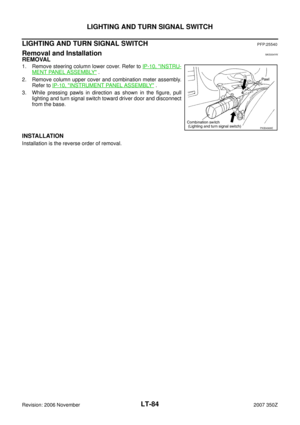 84
84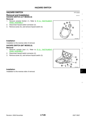 85
85 86
86 87
87 88
88 89
89 90
90 91
91 92
92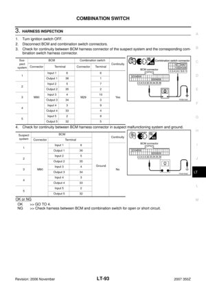 93
93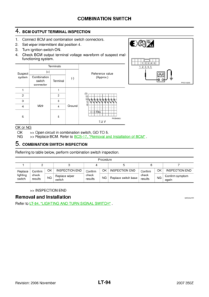 94
94 95
95 96
96 97
97 98
98 99
99 100
100 101
101 102
102 103
103 104
104 105
105 106
106 107
107 108
108 109
109 110
110 111
111 112
112 113
113 114
114 115
115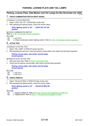 116
116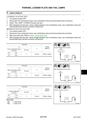 117
117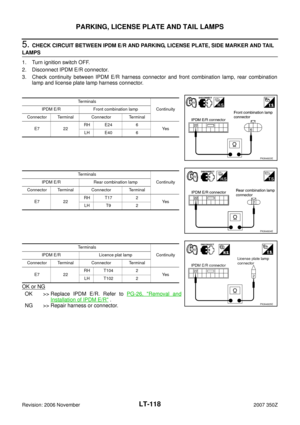 118
118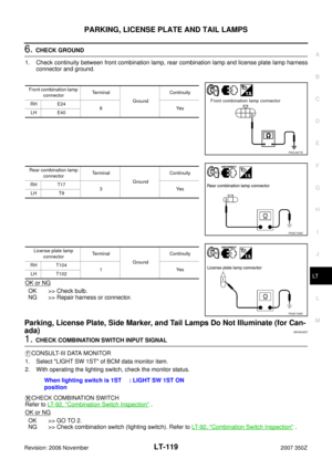 119
119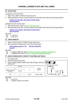 120
120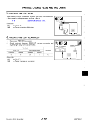 121
121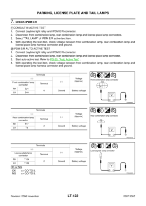 122
122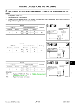 123
123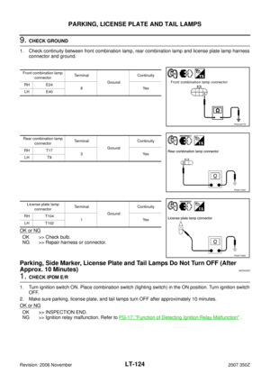 124
124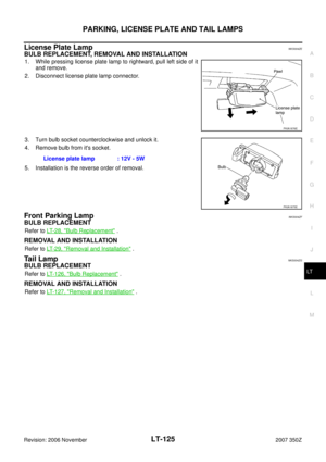 125
125 126
126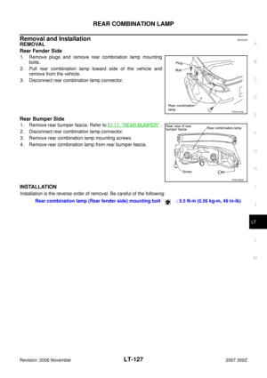 127
127 128
128 129
129 130
130 131
131 132
132 133
133 134
134 135
135 136
136 137
137 138
138 139
139 140
140 141
141 142
142 143
143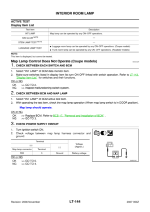 144
144 145
145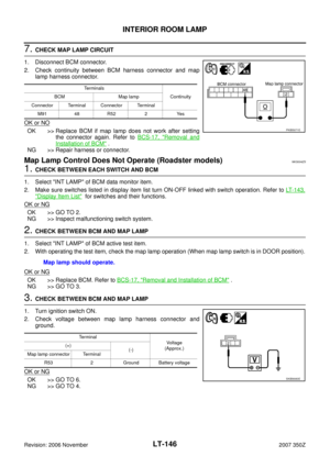 146
146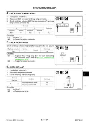 147
147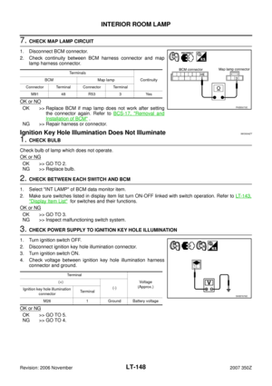 148
148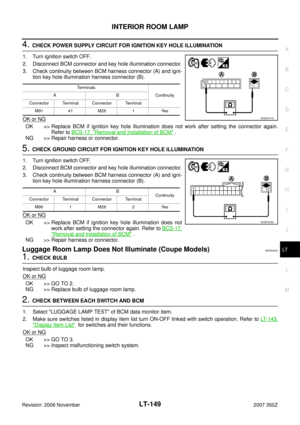 149
149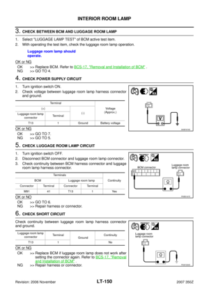 150
150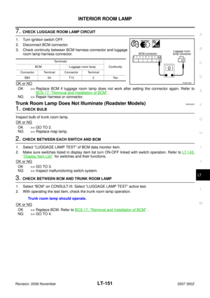 151
151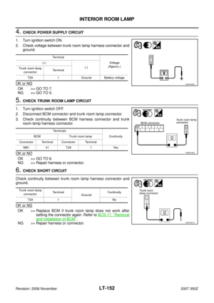 152
152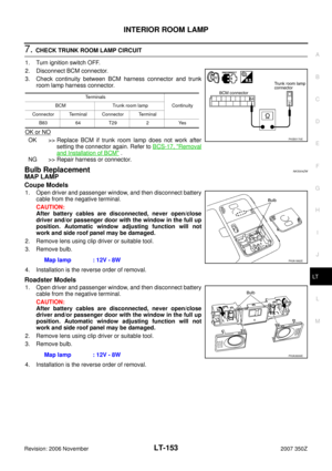 153
153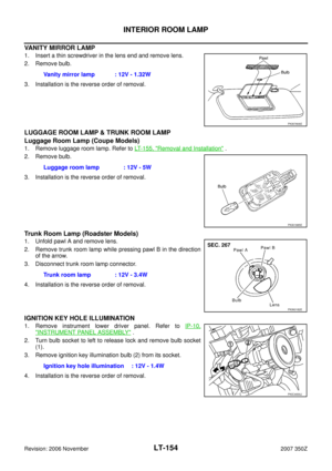 154
154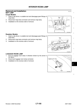 155
155 156
156 157
157 158
158 159
159 160
160 161
161 162
162 163
163 164
164 165
165 166
166 167
167 168
168 169
169 170
170 171
171