Page 353 of 720

DTC P0196 EOT SENSOR
EC-353
C
D
E
F
G
H
I
J
K
L
MA
EC
Revision: 2006 November2007 350Z
DTC Confirmation ProcedureNBS006TM
NOTE:
If DTC Confirmation Procedure has been previously conducted, always turn ignition switch OFF and wait at
least 10 seconds before conducting the next test.
TESTING CONDITION:
Before performing the following procedure, confirm that battery voltage is more than 11V at idle.
WITH CONSULT-III
1. Start engine and warm it up to normal operating temperature.
2. Turn ignition switch OFF and wait at least 10 seconds.
3. Start engine and let it idle for 5 minutes and 10 seconds.
4. Check 1st trip DTC.
If 1st trip DTC is detected, go to EC-354, "
Diagnostic Procedure" .
If 1st trip DTC is not detected, go to following steps.
5. Select “DATA MONITOR” mode with CONSULT-III.
6. Check that “COOLAN TEMP/S” indicates above 80°C (176°F).
If it is above 80°C (176°F), go to the following steps.
If it is below 80°C (176°F), warm engine up until “COOLAN TEMP/S” indicates more than 80°C
(176°F). Then go to the following steps.
7. Turn ignition switch OFF and soak the vehicle at cool place.
8. Turn ignition switch ON.
NOTE:
Do not turn ignition switch OFF until step 12
9. Select “DATA MONITOR” mode with CONSULT-III.
10. Check the following.
If they are within the specified range, go to following steps.
If they are out of the specified range, soak the vehicle to met the above conditions. Then go to following
steps.
NOTE:
�Do not turn ignition switch OFF.
�If it is supposed to need a long period of time, do not deplete the battery.
11. Start engine and let it idle for 5 minutes.
12. Check 1st trip DTC.
13. If 1st trip DTC is detected, go to EC-354, "
Diagnostic Procedure" .
WITH GST
Follow the procedure “WITH CONSULT-III” above.
COOLAN TEMP/S Below 40°C (104°F)
INT/A TEMP SE Below 40°C (104°F)
Difference between “COOLAN TEMP/S” and “INT/A TEMP SE” Within 6°C (11°F)
Page 362 of 720
EC-362
DTC P0222, P0223, P2132, P2133 TP SENSOR
Revision: 2006 November2007 350Z
DTC Confirmation ProcedureNBS0007P
NOTE:
If DTC Confirmation Procedure has been previously conducted, always turn ignition switch OFF and wait at
least 10 seconds before conducting the next test.
TESTING CONDITION:
Before performing the following procedure, confirm that battery voltage is more than 8V at idle.
WITH CONSULT-III
1. Start engine and let it idle for 1 second.
2. Check DTC.
3. If DTC is detected, go to EC-367, "
Diagnostic Procedure" .
WITH GST
Follow the procedure “WITH CONSULT-III” above.
Page 379 of 720

DTC P0327, P0328, P0332, P0333 KS
EC-379
C
D
E
F
G
H
I
J
K
L
MA
EC
Revision: 2006 November2007 350Z
DTC P0327, P0328, P0332, P0333 KSPFP:22060
Component DescriptionNBS0007X
The knock sensor is attached to the cylinder block. It senses engine
knocking using a piezoelectric element. A knocking vibration from
the cylinder block is sensed as vibrational pressure. This pressure is
converted into a voltage signal and sent to the ECM.
On Board Diagnosis LogicNBS0007Y
The MIL will not light up for these self-diagnoses.
DTC Confirmation ProcedureNBS0007Z
NOTE:
If DTC Confirmation Procedure has been previously conducted, always turn ignition switch OFF and wait at
least 10 seconds before conducting the next test.
TESTING CONDITION:
Before performing the following procedure, confirm that battery voltage is more than 10V at idle.
WITH CONSULT-III
1. Start engine and run it for at least 5 seconds at idle speed.
2. Check 1st trip DTC.
3. If 1st trip DTC is detected, go to EC-383, "
Diagnostic Procedure" .
WITH GST
Follow the procedure “WITH CONSULT-III” above.
1 : Knock sensor (bank 1)
2 : Knock sensor (bank 2)
PBIB3505E
DTC No.Trouble diagnosis
nameDTC detected condition Possible cause
P0327
0327
(Bank 1)
Knock sensor circuit
low inputAn excessively low voltage from the sensor is
sent to ECM.
�Harness or connectors
(The sensor circuit is open or shorted.)
�Knock sensor P0332
0332
(Bank 2)
P0328
0328
(Bank 1)
Knock sensor circuit
high inputAn excessively high voltage from the sensor is
sent to ECM.
P0333
0333
(Bank 2)
Page 387 of 720
DTC P0335 CKP SENSOR (POS)
EC-387
C
D
E
F
G
H
I
J
K
L
MA
EC
Revision: 2006 November2007 350Z
DTC Confirmation ProcedureNBS00087
NOTE:
If DTC Confirmation Procedure has been previously conducted, always turn ignition switch OFF and wait at
least 10 seconds before conducting the next test.
TESTING CONDITION:
Before performing the following procedure, confirm that battery voltage is more than 10.5V with igni-
tion switch ON.
WITH CONSULT-III
1. Crank engine for at least 2 seconds and run it for at least 5 seconds at idle speed.
2. Check 1st trip DTC.
3. If 1st trip DTC is detected, go to EC-390, "
Diagnostic Procedure" .
WITH GST
Follow the procedure “WITH CONSULT-III” above.
Page 395 of 720

DTC P0340, P0345 CMP SENSOR (PHASE)
EC-395
C
D
E
F
G
H
I
J
K
L
MA
EC
Revision: 2006 November2007 350Z
DTC No. Trouble diagnosis name DTC detecting condition Possible cause
P0340
0340
(Bank 1)
Camshaft position sen-
sor (PHASE) circuit
�The cylinder No. signal is not sent to ECM
for the first few seconds during engine
cranking.
�The cylinder No. signal is not sent to ECM
during engine running.
�The cylinder No. signal is not in the normal
pattern during engine running.
�Harness or connectors
[CMP sensor (PHASE) (bank 1) circuit is
open or shorted.]
�Camshaft position sensor (PHASE)
(bank 1)
�Camshaft (INT)
�Starter motor (Refer to SC-8, "START-
ING SYSTEM" .)
�Starting system circuit (Refer to SC-8,
"STARTING SYSTEM" .)
�Dead (Weak) battery
P0345
0345
(Bank 2)
�Harness or connectors
[CMP sensor (PHASE) (bank 2) circuit is
open or shorted.]
[CKP sensor (POS) circuit is shorted.]
[EVT control position sensor (bank 2) cir-
cuit is shorted.]
(APP sensor 2 circuit is shorted.)
(EVAP control system pressure sensor
circuit is shorted.)
(Refrigerant pressure sensor circuit is
shorted.)
�Camshaft position sensor (PHASE)
(bank 2)
�Crankshaft position sensor (POS)
�Exhaust valve timing control position
sensor (bank 2)
�Accelerator pedal position sensor
�EVAP control system pressure sensor
�Refrigerant pressure sensor
�Camshaft (INT)
�Starter motor (Refer to SC-8, "START-
ING SYSTEM" .)
�Starting system circuit (Refer to SC-8,
"STARTING SYSTEM" .)
�Dead (Weak) battery
Page 396 of 720
EC-396
DTC P0340, P0345 CMP SENSOR (PHASE)
Revision: 2006 November2007 350Z
DTC Confirmation ProcedureNBS0008F
NOTE:
If DTC Confirmation Procedure has been previously conducted, always turn ignition switch OFF and wait at
least 10 seconds before conducting the next test.
TESTING CONDITION:
Before performing the following procedure, confirm that battery voltage is more than 10.5V with igni-
tion switch ON.
WITH CONSULT-III
1. Crank engine for at least 2 seconds and run it for at least 5 seconds at idle speed.
2. Check 1st trip DTC.
3. If 1st trip DTC is detected, go to EC-400, "
Diagnostic Procedure" .
If 1st trip DTC is not detected, go to next step.
4. Maintaining engine speed at more than 800 rpm for at least 5 seconds.
5. Check 1st trip DTC.
6. If 1st trip DTC is detected, go to EC-400, "
Diagnostic Procedure" .
WITH GST
Follow the procedure “WITH CONSULT-III” above.
Page 408 of 720

EC-408
DTC P0420, P0430 THREE WAY CATALYST FUNCTION
Revision: 2006 November2007 350Z
3. CHECK INTAKE AIR LEAK
Listen for an intake air leak after the mass air flow sensor.
OK or NG
OK >> GO TO 4.
NG >> Repair or replace.
4. CHECK IGNITION TIMING
Check the following items. Refer to EC-71, "
Basic Inspection" .
OK or NG
OK >> GO TO 5.
NG >> Follow the EC-71, "
Basic Inspection" .
5. CHECK FUEL INJECTOR
1. Stop engine and turn ignition switch OFF.
2. Disconnect ECM harness connector.
3. Turn ignition switch ON.
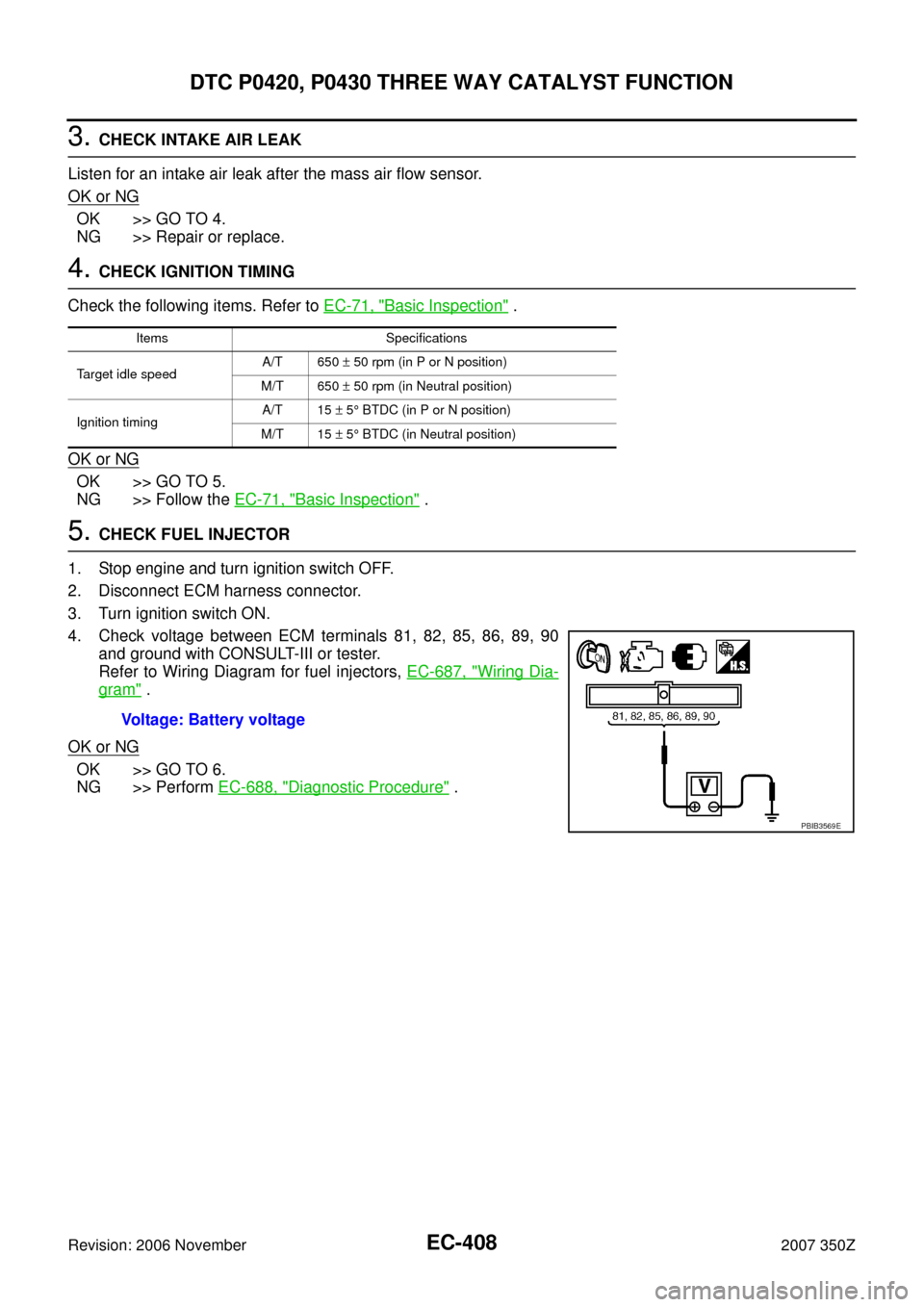
4. Check voltage between ECM terminals 81, 82, 85, 86, 89, 90
and ground with CONSULT-III or tester.
Refer to Wiring Diagram for fuel injectors, EC-687, "
Wiring Dia-
gram" .
OK or NG
OK >> GO TO 6.
NG >> Perform EC-688, "
Diagnostic Procedure" .
Items Specifications
Target idle speedA/T 650 ± 50 rpm (in P or N position)
M/T 650 ± 50 rpm (in Neutral position)
Ignition timingA/T 15 ± 5° BTDC (in P or N position)
M/T 15 ± 5° BTDC (in Neutral position)
Voltage: Battery voltage
PBIB3569E
Page 423 of 720

DTC P0443 EVAP CANISTER PURGE VOLUME CONTROL SOLENOID VALVE
EC-423
C
D
E
F
G
H
I
J
K
L
MA
EC
Revision: 2006 November2007 350Z
DTC P0443 EVAP CANISTER PURGE VOLUME CONTROL SOLENOID VALVE
PFP:14920
DescriptionNBS000FE
SYSTEM DESCRIPTION
*1: ECM determines the start signal status by the signals of engine speed and battery voltage.
*2: This signal is sent to the ECM through CAN communication line.
This system controls flow rate of fuel vapor from the EVAP canister. The opening of the vapor by-pass pas-
sage in the EVAP canister purge volume control solenoid valve changes to control the flow rate. The EVAP
canister purge volume control solenoid valve repeats ON/OFF operation according to the signal sent from the
ECM. The opening of the valve varies for optimum engine control. The optimum value stored in the ECM is
determined by considering various engine conditions. When the engine is operating, the flow rate of fuel vapor
from the EVAP canister is regulated as the air flow changes.
COMPONENT DESCRIPTION
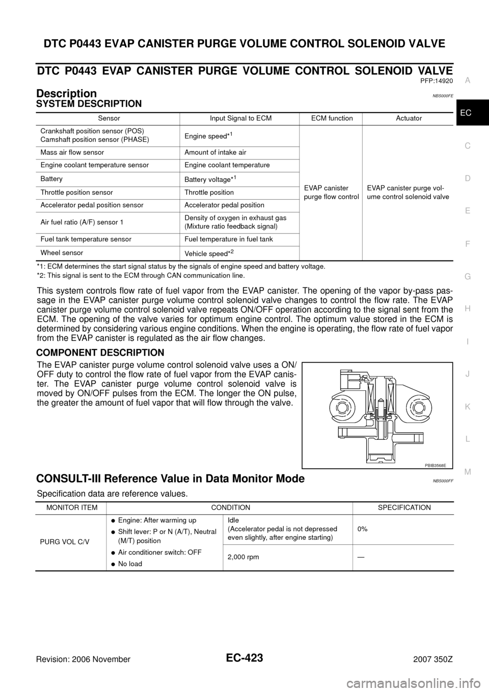
The EVAP canister purge volume control solenoid valve uses a ON/
OFF duty to control the flow rate of fuel vapor from the EVAP canis-
ter. The EVAP canister purge volume control solenoid valve is
moved by ON/OFF pulses from the ECM. The longer the ON pulse,
the greater the amount of fuel vapor that will flow through the valve.
CONSULT-III Reference Value in Data Monitor ModeNBS000FF
Specification data are reference values.
Sensor Input Signal to ECM ECM function Actuator
Crankshaft position sensor (POS)
Camshaft position sensor (PHASE)Engine speed*
1
EVAP canister
purge flow controlEVAP canister purge vol-
ume control solenoid valve Mass air flow sensor Amount of intake air
Engine coolant temperature sensor Engine coolant temperature
Battery
Battery voltage*
1
Throttle position sensor Throttle position
Accelerator pedal position sensor Accelerator pedal position
Air fuel ratio (A/F) sensor 1Density of oxygen in exhaust gas
(Mixture ratio feedback signal)
Fuel tank temperature sensor Fuel temperature in fuel tank
Wheel sensor
Vehicle speed*
2
PBIB3568E
MONITOR ITEM CONDITION SPECIFICATION
PURG VOL C/V
�Engine: After warming up
�Shift lever: P or N (A/T), Neutral
(M/T) position
�Air conditioner switch: OFF
�No loadIdle
(Accelerator pedal is not depressed
even slightly, after engine starting)0%
2,000 rpm —