Page 693 of 720

FUEL PUMP
EC-693
C
D
E
F
G
H
I
J
K
L
MA
EC
Revision: 2006 November2007 350Z
Specification data are reference values and are measured between each terminal and ground.
CAUTION:
Do not use ECM ground terminals when measuring input/output voltage. Doing so may result in dam-
age to the ECM's transistor. Use a ground other than ECM terminals, such as the ground.
Diagnostic ProcedureNBS000HZ
1. CHECK OVERALL FUNCTION
1. Turn ignition switch ON.
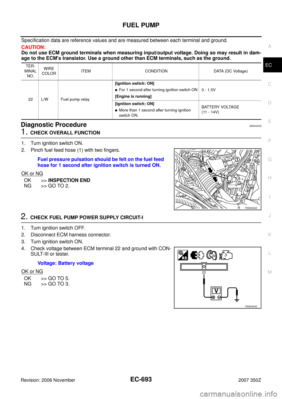
2. Pinch fuel feed hose (1) with two fingers.
OK or NG
OK >>INSPECTION END
NG >> GO TO 2.
2. CHECK FUEL PUMP POWER SUPPLY CIRCUIT-I
1. Turn ignition switch OFF.
2. Disconnect ECM harness connector.
3. Turn ignition switch ON.
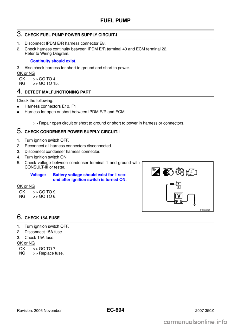
4. Check voltage between ECM terminal 22 and ground with CON-
SULT-III or tester.
OK or NG
OK >> GO TO 5.
NG >> GO TO 3.
TER-
MINAL
NO.WIRE
COLORITEM CONDITION DATA (DC Voltage)
22 L/W Fuel pump relay[Ignition switch: ON]
�For 1 second after turning ignition switch ON
[Engine is running]0 - 1.5V
[Ignition switch: ON]
�More than 1 second after turning ignition
switch ON.BATTERY VOLTAGE
(11 - 14V)
Fuel pressure pulsation should be felt on the fuel feed
hose for 1 second after ignition switch is turned ON.
PBIB3524E
Voltage: Battery voltage
PBIB3583E
Page 694 of 720

EC-694
FUEL PUMP
Revision: 2006 November2007 350Z
3. CHECK FUEL PUMP POWER SUPPLY CIRCUIT-I
1. Disconnect IPDM E/R harness connector E8.
2. Check harness continuity between IPDM E/R terminal 40 and ECM terminal 22.
Refer to Wiring Diagram.
3. Also check harness for short to ground and short to power.
OK or NG
OK >> GO TO 4.
NG >> GO TO 15.
4. DETECT MALFUNCTIONING PART
Check the following.
�Harness connectors E10, F1
�Harness for open or short between IPDM E/R and ECM
>> Repair open circuit or short to ground or short to power in harness or connectors.
5. CHECK CONDENSER POWER SUPPLY CIRCUIT-I
1. Turn ignition switch OFF.
2. Reconnect all harness connectors disconnected.
3. Disconnect condenser harness connector.
4. Turn ignition switch ON.
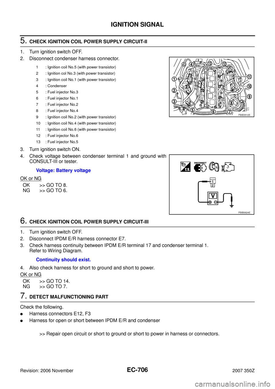
5. Check voltage between condenser terminal 1 and ground with
CONSULT-III or tester.
OK or NG
OK >> GO TO 9.
NG >> GO TO 6.
6. CHECK 15A FUSE
1. Turn ignition switch OFF.
2. Disconnect 15A fuse.
3. Check 15A fuse.
OK or NG
OK >> GO TO 7.
NG >> Replace fuse.Continuity should exist.
Voltage: Battery voltage should exist for 1 sec-
ond after ignition switch is turned ON.
PBIB0624E
Page 700 of 720
EC-700
IGNITION SIGNAL
Revision: 2006 November2007 350Z
Specification data are reference values and are measured between each terminal and ground.
CAUTION:
Do not use ECM ground terminals when measuring input/output voltage. Doing so may result in dam-
age to the ECM's transistor. Use a ground other than ECM terminals, such as the ground.
TER-
MINAL
NO.WIRE
COLORITEM CONDITION DATA (DC Voltage)
24 BR/YECM relay
(Self shut-off)[Engine is running]
[Ignition switch: OFF]
�For a few seconds after turning ignition
switch OFF0 - 1.5V
[Ignition switch: OFF]
�More than a few seconds after turning igni-
tion switch OFFBATTERY VOLTAGE
(11 - 14V)
125 R Power supply for ECM[Ignition switch: ON]BATTERY VOLTAGE
(11 - 14V)
Page 705 of 720
IGNITION SIGNAL
EC-705
C
D
E
F
G
H
I
J
K
L
MA
EC
Revision: 2006 November2007 350Z
3. CHECK OVERALL FUNCTION
Without CONSULT-III
1. Let engine idle.
2. Read the voltage signal between ECM terminals 11, 12, 15, 16,
19, 20 and ground with an oscilloscope.
3. Verify that the oscilloscope screen shows the signal wave as
shown below.
NOTE:
The pulse cycle changes depending on rpm at idle.
OK or NG
OK >>INSPECTION END
NG >> GO TO 10.
4. CHECK IGNITION COIL POWER SUPPLY CIRCUIT-I
1. Turn ignition switch OFF, wait at least 10 seconds and then turn ON.
2. Check voltage between ECM terminals 125 and ground with
CONSULT-III or tester.
OK or NG
OK >> GO TO 5.
NG >> Go to EC-142, "
POWER SUPPLY AND GROUND CIR-
CUIT" .
PBIB3584E
PBIB3543E
Voltage: Battery voltage
PBIB3585E
Page 706 of 720

EC-706
IGNITION SIGNAL
Revision: 2006 November2007 350Z
5. CHECK IGNITION COIL POWER SUPPLY CIRCUIT-II
1. Turn ignition switch OFF.
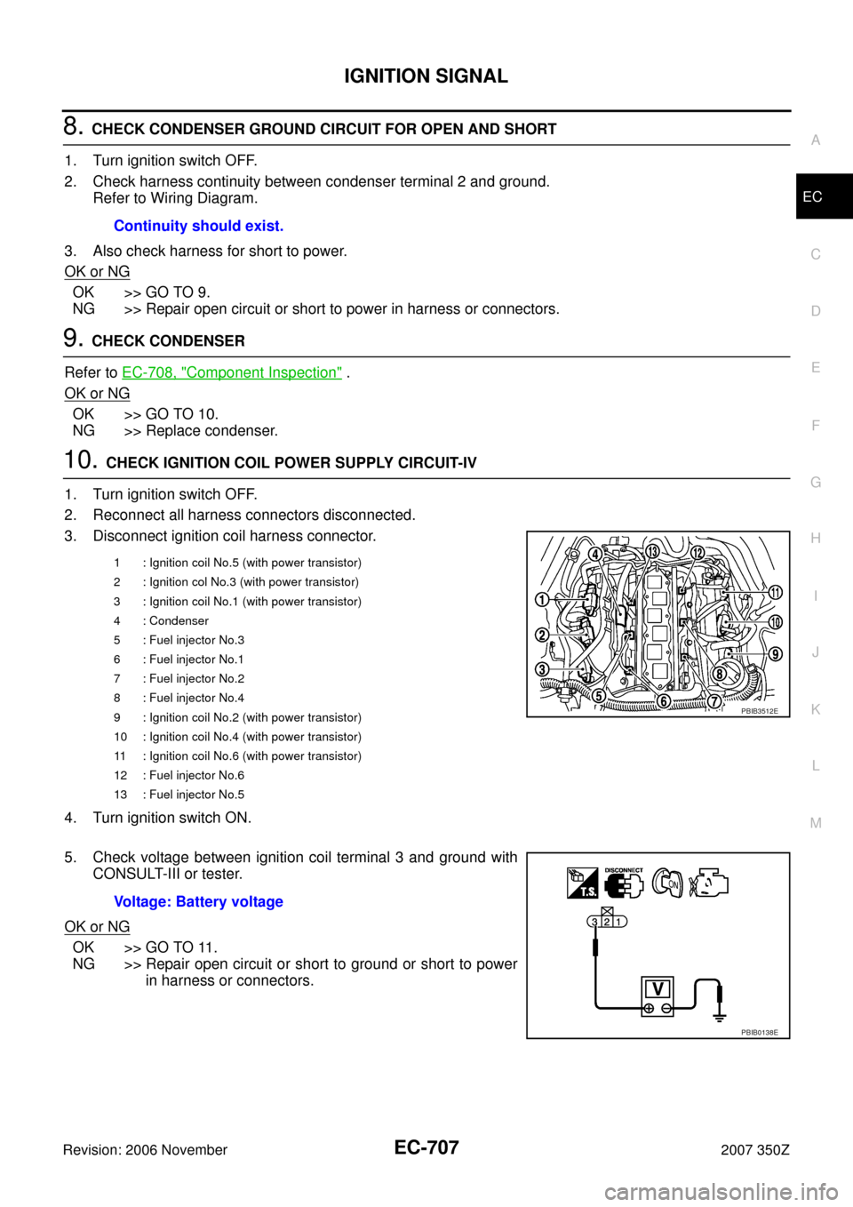
2. Disconnect condenser harness connector.
3. Turn ignition switch ON.
4. Check voltage between condenser terminal 1 and ground with
CONSULT-III or tester.
OK or NG
OK >> GO TO 8.
NG >> GO TO 6.
6. CHECK IGNITION COIL POWER SUPPLY CIRCUIT-III
1. Turn ignition switch OFF.
2. Disconnect IPDM E/R harness connector E7.
3. Check harness continuity between IPDM E/R terminal 17 and condenser terminal 1.
Refer to Wiring Diagram.
4. Also check harness for short to ground and short to power.
OK or NG
OK >> GO TO 14.
NG >> GO TO 7.
7. DETECT MALFUNCTIONING PART
Check the following.
�Harness connectors E12, F3
�Harness for open or short between IPDM E/R and condenser
>> Repair open circuit or short to ground or short to power in harness or connectors.
1 : Ignition coil No.5 (with power transistor)
2 : Ignition col No.3 (with power transistor)
3 : Ignition coil No.1 (with power transistor)
4 : Condenser
5 : Fuel injector No.3
6 : Fuel injector No.1
7 : Fuel injector No.2
8 : Fuel injector No.4
9 : Ignition coil No.2 (with power transistor)
10 : Ignition coil No.4 (with power transistor)
11 : Ignition coil No.6 (with power transistor)
12 : Fuel injector No.6
13 : Fuel injector No.5
Voltage: Battery voltage
PBIB3512E
PBIB0624E
Continuity should exist.
Page 707 of 720

IGNITION SIGNAL
EC-707
C
D
E
F
G
H
I
J
K
L
MA
EC
Revision: 2006 November2007 350Z
8. CHECK CONDENSER GROUND CIRCUIT FOR OPEN AND SHORT
1. Turn ignition switch OFF.
2. Check harness continuity between condenser terminal 2 and ground.
Refer to Wiring Diagram.
3. Also check harness for short to power.
OK or NG
OK >> GO TO 9.
NG >> Repair open circuit or short to power in harness or connectors.
9. CHECK CONDENSER
Refer to EC-708, "
Component Inspection" .
OK or NG
OK >> GO TO 10.
NG >> Replace condenser.
10. CHECK IGNITION COIL POWER SUPPLY CIRCUIT-IV
1. Turn ignition switch OFF.
2. Reconnect all harness connectors disconnected.
3. Disconnect ignition coil harness connector.
4. Turn ignition switch ON.
5. Check voltage between ignition coil terminal 3 and ground with
CONSULT-III or tester.
OK or NG
OK >> GO TO 11.
NG >> Repair open circuit or short to ground or short to power
in harness or connectors. Continuity should exist.
1 : Ignition coil No.5 (with power transistor)
2 : Ignition col No.3 (with power transistor)
3 : Ignition coil No.1 (with power transistor)
4 : Condenser
5 : Fuel injector No.3
6 : Fuel injector No.1
7 : Fuel injector No.2
8 : Fuel injector No.4
9 : Ignition coil No.2 (with power transistor)
10 : Ignition coil No.4 (with power transistor)
11 : Ignition coil No.6 (with power transistor)
12 : Fuel injector No.6
13 : Fuel injector No.5
PBIB3512E
Voltage: Battery voltage
PBIB0138E
Page 718 of 720

EC-718
SERVICE DATA AND SPECIFICATIONS (SDS)
Revision: 2006 November2007 350Z
SERVICE DATA AND SPECIFICATIONS (SDS)PFP:00030
Fuel PressureNBS000IJ
Idle Speed and Ignition TimingNBS000IK
*: Under the following conditions:
�Air conditioner switch: OFF
�Electric load: OFF (Lights, heater fan & rear window defogger)
�Steering wheel: Kept in straight-ahead position
Calculated Load ValueNBS000IL
Mass Air Flow SensorNBS000IM
*: Engine is warmed up to normal operating temperature and running under no load.
Intake Air Temperature SensorNBS000IN
Engine Coolant Temperature SensorNBS000IO
Air Fuel Ratio (A/F) Sensor 1 HeaterNBS000IP
Heated Oxygen sensor 2 HeaterNBS000IQ
Crankshaft Position Sensor (POS)NBS000IR
Refer to EC-393, "Component Inspection" .
Camshaft Position Sensor (PHASE)NBS000IS
Refer to EC-405, "Component Inspection" .
Fuel pressure at idling kPa (kg/cm2 , psi)Approximately 350 (3.57, 51)
Target idle speedA/T No load* (in P or N position)
650 ± 50 rpm
M/T No load* (in Neutral position)
Air conditioner: ONA/T In P or N position 650 rpm or more
M/T In Neutral position 800 rpm or more
Ignition timingA/T In P or N position
15° ± 5° BTDC
M/T In Neutral position
Conditions Calculated load value % (Using CONSULT-III or GST)
At idle5 - 35
At 2,500 rpm5 - 35
Supply voltageBattery voltage (11 - 14V)
Output voltage at idle0.8 - 1.1V*
Mass air flow (Using CONSULT-III or GST)2.0 - 6.0 g·m/sec at idle*
7.0 - 20.0 g·m/sec at 2,500 rpm*
Temperature °C (°F) Resistance kΩ
25 (77)1.800 - 2.200
Temperature °C (°F) Resistance kΩ
20 (68)2.37 - 2.63
50 (122)0.68 - 1.00
90 (194)0.236 - 0.260
Resistance [at 25°C (77°F)] 1.8 - 2.44Ω
Resistance [at 25°C (77°F)] 3.4 - 4.4Ω