Page 302 of 720

EC-302
DTC P0138, P0158 HO2S2
Revision: 2006 November2007 350Z
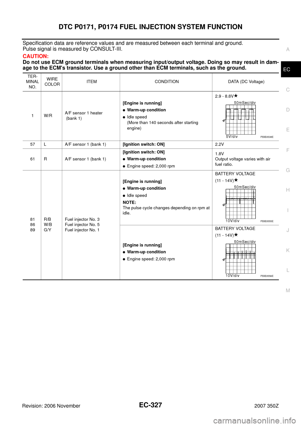
Specification data are reference values and are measured between each terminal and ground.
CAUTION:
Do not use ECM ground terminals when measuring input/output voltage. Doing so may result in dam-
age to the ECM's transistor. Use a ground other than ECM terminals, such as the ground.
TER-
MINAL
NO.WIRE
COLORITEM CONDITION DATA (DC Voltage)
17 PHeated oxygen sensor 2
heater (bank 1)[Engine is running]
�Engine speed: Below 3,600 rpm after the
following conditions are met.
–Engine: After warming up
–Keeping the engine speed between 3,500
and 4,000 rpm for 1 minute and at idle for 1
minute under no load.0 - 14V
[Ignition switch: ON]
�Engine stopped
[Engine is running]
�Engine speed: Above 3,600 rpmBATTERY VOLTAGE
(11 - 14V)
76 W/RHeated oxygen sensor 2
(bank 1)[Engine is running]
�Revving engine from idle to 3,000 rpm
quickly after the following conditions are
met.
–Engine: After warming up
–Keeping the engine speed between 3,500
and 4,000 rpm for 1 minute and at idle for 1
minute under no load.0 - 1.0V
84 GSensor ground
(Heated oxygen sensor 2,
Engine coolant temperature
sensor, Engine oil tempera-
ture sensor)[Engine is running]
�Warm-up condition
�Idle speed0V
PBIB3545E
Page 304 of 720

EC-304
DTC P0138, P0158 HO2S2
Revision: 2006 November2007 350Z
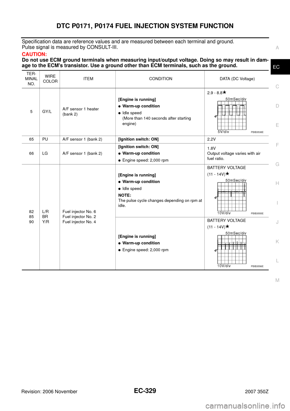
Specification data are reference values and are measured between each terminal and ground.
CAUTION:
Do not use ECM ground terminals when measuring input/output voltage. Doing so may result in dam-
age to the ECM's transistor. Use a ground other than ECM terminals, such as the ground.
TER-
MINAL
NO.WIRE
COLORITEM CONDITION DATA (DC Voltage)
33 PU/WHeated oxygen sensor 2
heater (bank 2)[Engine is running]
�Engine speed: Below 3,600 rpm after the
following conditions are met.
–Engine: After warming up
–Keeping the engine speed between 3,500
and 4,000 rpm for 1 minute and at idle for 1
minute under no load.0 - 14V
[Ignition switch: ON]
�Engine stopped
[Engine is running]
�Engine speed: Above 3,600 rpmBATTERY VOLTAGE
(11 - 14V)
80 R/YHeated oxygen sensor 2
(bank 2)[Engine is running]
�Revving engine from idle to 3,000 rpm
quickly after the following conditions are
met.
–Engine: After warming up
–Keeping the engine speed between 3,500
and 4,000 rpm for 1 minute and at idle for 1
minute under no load.0 - 1.0V
84 GSensor ground
(Heated oxygen sensor 2,
Engine coolant temperature
sensor, Engine oil tempera-
ture sensor)[Engine is running]
�Warm-up condition
�Idle speed0V
PBIB3545E
Page 316 of 720

EC-316
DTC P0139, P0159 HO2S2
Revision: 2006 November2007 350Z
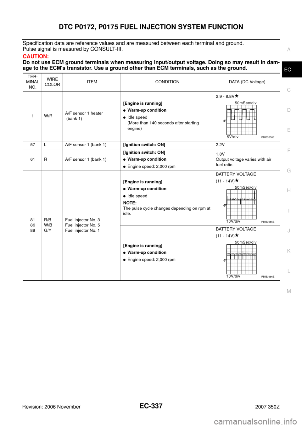
Specification data are reference values and are measured between each terminal and ground.
CAUTION:
Do not use ECM ground terminals when measuring input/output voltage. Doing so may result in dam-
age to the ECM's transistor. Use a ground other than ECM terminals, such as the ground.
TER-
MINAL
NO.WIRE
COLORITEM CONDITION DATA (DC Voltage)
17 PHeated oxygen sensor 2
heater (bank 1)[Engine is running]
�Engine speed: Below 3,600 rpm after the
following conditions are met.
–Engine: After warming up
–Keeping the engine speed between 3,500
and 4,000 rpm for 1 minute and at idle for 1
minute under no load.0 - 14V
[Ignition switch: ON]
�Engine stopped
[Engine is running]
�Engine speed: Above 3,600 rpmBATTERY VOLTAGE
(11 - 14V)
76 W/RHeated oxygen sensor 2
(bank 1)[Engine is running]
�Revving engine from idle to 3,000 rpm
quickly after the following conditions are
met.
–Engine: After warming up
–Keeping the engine speed between 3,500
and 4,000 rpm for 1 minute and at idle for 1
minute under no load.0 - 1.0V
84 GSensor ground
(Heated oxygen sensor 2,
Engine coolant temperature
sensor, Engine oil tempera-
ture sensor)[Engine is running]
�Warm-up condition
�Idle speed0V
PBIB3545E
Page 318 of 720

EC-318
DTC P0139, P0159 HO2S2
Revision: 2006 November2007 350Z
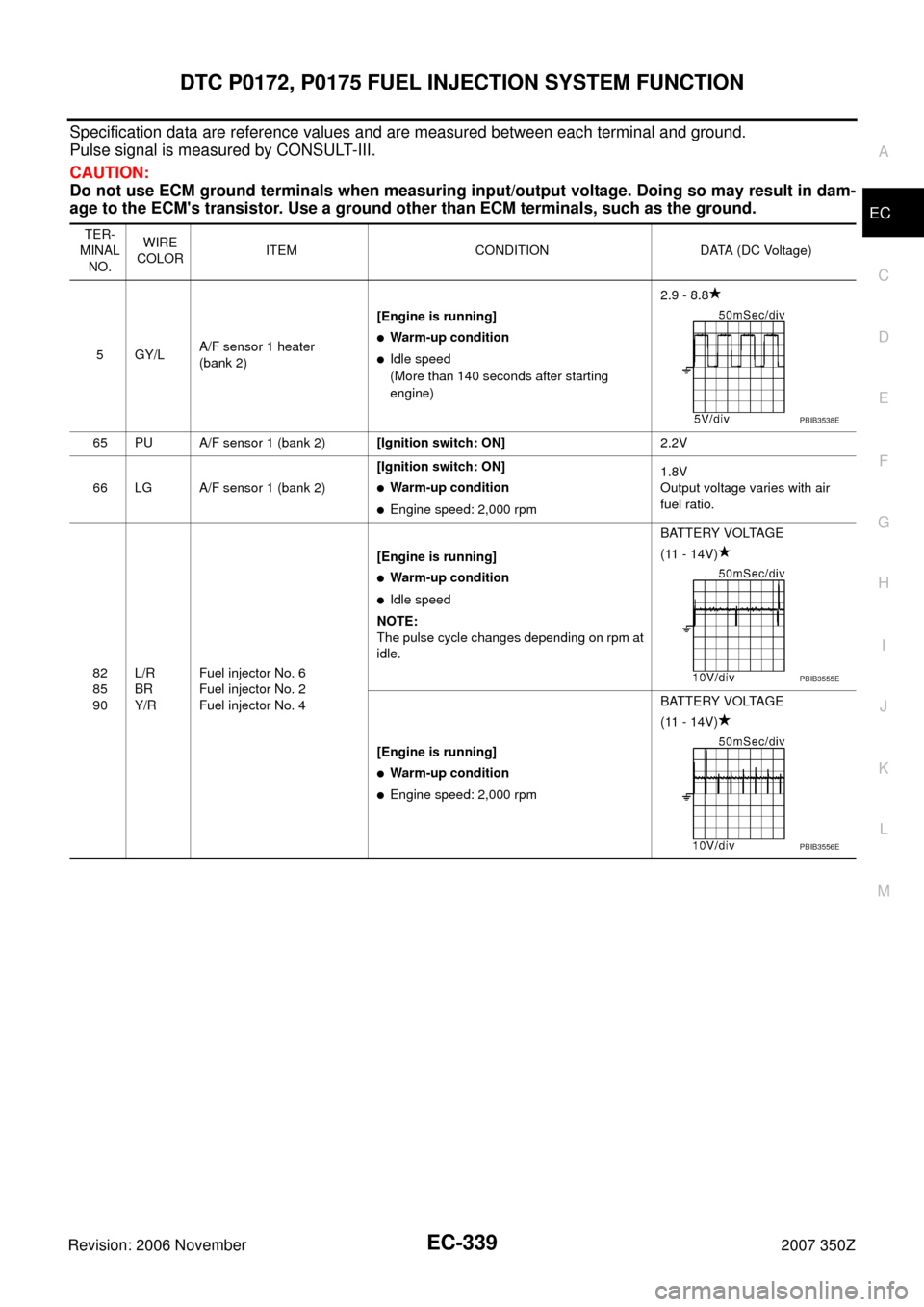
Specification data are reference values and are measured between each terminal and ground.
CAUTION:
Do not use ECM ground terminals when measuring input/output voltage. Doing so may result in dam-
age to the ECM's transistor. Use a ground other than ECM terminals, such as the ground.
TER-
MINAL
NO.WIRE
COLORITEM CONDITION DATA (DC Voltage)
33 PU/WHeated oxygen sensor 2
heater (bank 2)[Engine is running]
�Engine speed: Below 3,600 rpm after the
following conditions are met.
–Engine: After warming up
–Keeping the engine speed between 3,500
and 4,000 rpm for 1 minute and at idle for 1
minute under no load.0 - 14V
[Ignition switch: ON]
�Engine stopped
[Engine is running]
�Engine speed: Above 3,600 rpmBATTERY VOLTAGE
(11 - 14V)
80 R/YHeated oxygen sensor 2
(bank 2)[Engine is running]
�Revving engine from idle to 3,000 rpm
quickly after the following conditions are
met.
–Engine: After warming up
–Keeping the engine speed between 3,500
and 4,000 rpm for 1 minute and at idle for 1
minute under no load.0 - 1.0V
84 GSensor ground
(Heated oxygen sensor 2,
Engine coolant temperature
sensor, Engine oil tempera-
ture sensor)[Engine is running]
�Warm-up condition
�Idle speed0V
PBIB3545E
Page 327 of 720

DTC P0171, P0174 FUEL INJECTION SYSTEM FUNCTION
EC-327
C
D
E
F
G
H
I
J
K
L
MA
EC
Revision: 2006 November2007 350Z
Specification data are reference values and are measured between each terminal and ground.
Pulse signal is measured by CONSULT-III.
CAUTION:
Do not use ECM ground terminals when measuring input/output voltage. Doing so may result in dam-
age to the ECM's transistor. Use a ground other than ECM terminals, such as the ground.
TER-
MINAL
NO.WIRE
COLORITEM CONDITION DATA (DC Voltage)
1W/RA/F sensor 1 heater
(bank 1)[Engine is running]
�Warm-up condition
�Idle speed
(More than 140 seconds after starting
engine)2.9 - 8.8V
57 L A/F sensor 1 (bank 1)[Ignition switch: ON]2.2V
61 R A/F sensor 1 (bank 1)[Ignition switch: ON]
�Warm-up condition
�Engine speed: 2,000 rpm1.8V
Output voltage varies with air
fuel ratio.
81
86
89R/B
W/B
G/YFuel injector No. 3
Fuel injector No. 5
Fuel injector No. 1 [Engine is running]
�Warm-up condition
�Idle speed
NOTE:
The pulse cycle changes depending on rpm at
idle.BATTERY VOLTAGE
(11 - 14V)
[Engine is running]
�Warm-up condition
�Engine speed: 2,000 rpmBATTERY VOLTAGE
(11 - 14V)
PBIB3538E
PBIB3555E
PBIB3556E
Page 329 of 720

DTC P0171, P0174 FUEL INJECTION SYSTEM FUNCTION
EC-329
C
D
E
F
G
H
I
J
K
L
MA
EC
Revision: 2006 November2007 350Z
Specification data are reference values and are measured between each terminal and ground.
Pulse signal is measured by CONSULT-III.
CAUTION:
Do not use ECM ground terminals when measuring input/output voltage. Doing so may result in dam-
age to the ECM's transistor. Use a ground other than ECM terminals, such as the ground.
TER-
MINAL
NO.WIRE
COLORITEM CONDITION DATA (DC Voltage)
5GY/LA/F sensor 1 heater
(bank 2)[Engine is running]
�Warm-up condition
�Idle speed
(More than 140 seconds after starting
engine)2.9 - 8.8
65 PU A/F sensor 1 (bank 2)[Ignition switch: ON]2.2V
66 LG A/F sensor 1 (bank 2)[Ignition switch: ON]
�Warm-up condition
�Engine speed: 2,000 rpm1.8V
Output voltage varies with air
fuel ratio.
82
85
90L/R
BR
Y/RFuel injector No. 6
Fuel injector No. 2
Fuel injector No. 4[Engine is running]
�Warm-up condition
�Idle speed
NOTE:
The pulse cycle changes depending on rpm at
idle.BATTERY VOLTAGE
(11 - 14V)
[Engine is running]
�Warm-up condition
�Engine speed: 2,000 rpmBATTERY VOLTAGE
(11 - 14V)
PBIB3538E
PBIB3555E
PBIB3556E
Page 337 of 720

DTC P0172, P0175 FUEL INJECTION SYSTEM FUNCTION
EC-337
C
D
E
F
G
H
I
J
K
L
MA
EC
Revision: 2006 November2007 350Z
Specification data are reference values and are measured between each terminal and ground.
Pulse signal is measured by CONSULT-III.
CAUTION:
Do not use ECM ground terminals when measuring input/output voltage. Doing so may result in dam-
age to the ECM's transistor. Use a ground other than ECM terminals, such as the ground.
TER-
MINAL
NO.WIRE
COLORITEM CONDITION DATA (DC Voltage)
1W/RA/F sensor 1 heater
(bank 1)[Engine is running]
�Warm-up condition
�Idle speed
(More than 140 seconds after starting
engine)2.9 - 8.8V
57 L A/F sensor 1 (bank 1)[Ignition switch: ON]2.2V
61 R A/F sensor 1 (bank 1)[Ignition switch: ON]
�Warm-up condition
�Engine speed: 2,000 rpm1.8V
Output voltage varies with air
fuel ratio.
81
86
89R/B
W/B
G/YFuel injector No. 3
Fuel injector No. 5
Fuel injector No. 1 [Engine is running]
�Warm-up condition
�Idle speed
NOTE:
The pulse cycle changes depending on rpm at
idle.BATTERY VOLTAGE
(11 - 14V)
[Engine is running]
�Warm-up condition
�Engine speed: 2,000 rpmBATTERY VOLTAGE
(11 - 14V)
PBIB3538E
PBIB3555E
PBIB3556E
Page 339 of 720

DTC P0172, P0175 FUEL INJECTION SYSTEM FUNCTION
EC-339
C
D
E
F
G
H
I
J
K
L
MA
EC
Revision: 2006 November2007 350Z
Specification data are reference values and are measured between each terminal and ground.
Pulse signal is measured by CONSULT-III.
CAUTION:
Do not use ECM ground terminals when measuring input/output voltage. Doing so may result in dam-
age to the ECM's transistor. Use a ground other than ECM terminals, such as the ground.
TER-
MINAL
NO.WIRE
COLORITEM CONDITION DATA (DC Voltage)
5GY/LA/F sensor 1 heater
(bank 2)[Engine is running]
�Warm-up condition
�Idle speed
(More than 140 seconds after starting
engine)2.9 - 8.8
65 PU A/F sensor 1 (bank 2)[Ignition switch: ON]2.2V
66 LG A/F sensor 1 (bank 2)[Ignition switch: ON]
�Warm-up condition
�Engine speed: 2,000 rpm1.8V
Output voltage varies with air
fuel ratio.
82
85
90L/R
BR
Y/RFuel injector No. 6
Fuel injector No. 2
Fuel injector No. 4[Engine is running]
�Warm-up condition
�Idle speed
NOTE:
The pulse cycle changes depending on rpm at
idle.BATTERY VOLTAGE
(11 - 14V)
[Engine is running]
�Warm-up condition
�Engine speed: 2,000 rpmBATTERY VOLTAGE
(11 - 14V)
PBIB3538E
PBIB3555E
PBIB3556E