Page 203 of 720

DTC P0101, P010B MAF SENSOR
EC-203
C
D
E
F
G
H
I
J
K
L
MA
EC
Revision: 2006 November2007 350Z
Specification data are reference values and are measured between each terminal and ground.
CAUTION:
Do not use ECM ground terminals when measuring input/output voltage. Doing so may result in dam-
age to the ECM's transistor. Use a ground other than ECM terminals, such as the ground.
Diagnostic ProcedureNBS00055
1. INSPECTION START
Which malfunction (A or B) is duplicated?
A or B
A>>GO TO 3.
B>>GO TO 2.
2. CHECK INTAKE SYSTEM
Check the following for connection.
�Air duct
�Va c u u m h o s e s
�Intake air passage between air duct and intake manifold
OK or NG
OK >> GO TO 3.
NG >> Reconnect the parts.
TER-
MINAL
NO.WIRE
COLORITEM CONDITION DATA (DC Voltage)
24 BR/YECM relay
(Self shut-off)[Engine is running]
[Ignition switch: OFF]
�For a few seconds after turning ignition
switch OFF0 - 1.5V
79 GY/RMass air flow sensor
(bank2)[Engine is running]
�Warm-up condition
�Idle speed0.8 - 1.1V
[Engine is running]
�Warm-up condition
�Engine speed: 2,500 rpm1.4 - 1.7V
94 L/YSensor ground
[Mass air flow sensor (bank
2)][Engine is running]
�Warm-up condition
�Idle speed0V
125 R Power supply for ECM[Ignition switch: ON]BATTERY VOLTAGE
(11 - 14V)
Page 205 of 720

DTC P0101, P010B MAF SENSOR
EC-205
C
D
E
F
G
H
I
J
K
L
MA
EC
Revision: 2006 November2007 350Z
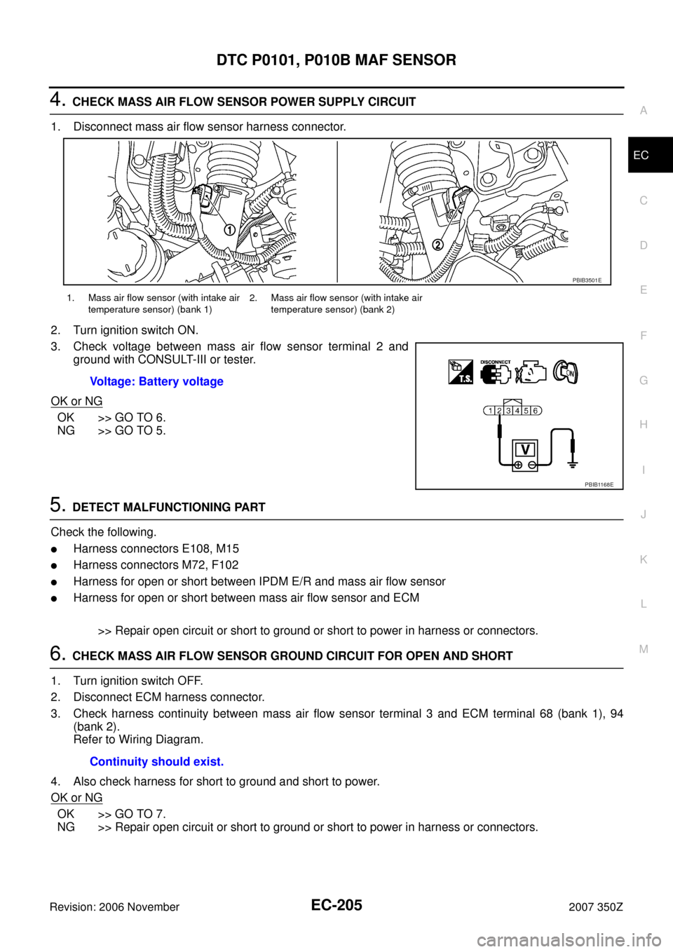
4. CHECK MASS AIR FLOW SENSOR POWER SUPPLY CIRCUIT
1. Disconnect mass air flow sensor harness connector.
2. Turn ignition switch ON.
3. Check voltage between mass air flow sensor terminal 2 and
ground with CONSULT-III or tester.
OK or NG
OK >> GO TO 6.
NG >> GO TO 5.
5. DETECT MALFUNCTIONING PART
Check the following.
�Harness connectors E108, M15
�Harness connectors M72, F102
�Harness for open or short between IPDM E/R and mass air flow sensor
�Harness for open or short between mass air flow sensor and ECM
>> Repair open circuit or short to ground or short to power in harness or connectors.
6. CHECK MASS AIR FLOW SENSOR GROUND CIRCUIT FOR OPEN AND SHORT
1. Turn ignition switch OFF.
2. Disconnect ECM harness connector.
3. Check harness continuity between mass air flow sensor terminal 3 and ECM terminal 68 (bank 1), 94
(bank 2).
Refer to Wiring Diagram.
4. Also check harness for short to ground and short to power.
OK or NG
OK >> GO TO 7.
NG >> Repair open circuit or short to ground or short to power in harness or connectors.
1. Mass air flow sensor (with intake air
temperature sensor) (bank 1)2. Mass air flow sensor (with intake air
temperature sensor) (bank 2)
Voltage: Battery voltage
PBIB3501E
PBIB1168E
Continuity should exist.
Page 211 of 720
DTC P0102, P0103, P010C, P010D MAF SENSOR
EC-211
C
D
E
F
G
H
I
J
K
L
MA
EC
Revision: 2006 November2007 350Z
Specification data are reference values and are measured between each terminal and ground.
CAUTION:
Do not use ECM ground terminals when measuring input/output voltage. Doing so may result in dam-
age to the ECM's transistor. Use a ground other than ECM terminals, such as the ground.
TER-
MINAL
NO.WIRE
COLORITEM CONDITION DATA (DC Voltage)
24 BR/YECM relay
(Self shut-off)[Engine is running]
[Ignition switch: OFF]
�For a few seconds after turning ignition
switch OFF0 - 1.5V
68 BSensor ground
[Mass air flow sensor
(bank1), Intake air tempera-
ture sensor (bank 1)][Engine is running]
�Warm-up condition
�Idle speed0V
77 L/WMass air flow sensor
(bank1)[Engine is running]
�Warm-up condition
�Idle speed0.8 - 1.1V
[Engine is running]
�Warm-up condition
�Engine speed: 2,500 rpm1.4 - 1.7V
125 R Power supply for ECM[Ignition switch: ON]BATTERY VOLTAGE
(11 - 14V)
Page 213 of 720

DTC P0102, P0103, P010C, P010D MAF SENSOR
EC-213
C
D
E
F
G
H
I
J
K
L
MA
EC
Revision: 2006 November2007 350Z
Specification data are reference values and are measured between each terminal and ground.
CAUTION:
Do not use ECM ground terminals when measuring input/output voltage. Doing so may result in dam-
age to the ECM's transistor. Use a ground other than ECM terminals, such as the ground.
Diagnostic ProcedureNBS006U2
1. INSPECTION START
Confirm the detected DTC.
Which DTC is detected?
P0102, P010C>>GO TO 2.
P0103, P010D>>GO TO 3.
2. CHECK INTAKE SYSTEM
Check the following for connection.
�Air duct
�Va c u u m h o s e s
�Intake air passage between air duct and intake manifold
OK or NG
OK >> GO TO 3.
NG >> Reconnect the parts.
TER-
MINAL
NO.WIRE
COLORITEM CONDITION DATA (DC Voltage)
24 BR/YECM relay
(Self shut-off)[Engine is running]
[Ignition switch: OFF]
�For a few seconds after turning ignition
switch OFF0 - 1.5V
79 GY/RMass air flow sensor
(bank2)[Engine is running]
�Warm-up condition
�Idle speed0.8 - 1.1V
[Engine is running]
�Warm-up condition
�Engine speed: 2,500 rpm1.4 - 1.7V
94 L/YSensor ground
[Mass air flow sensor (bank
2)][Engine is running]
�Warm-up condition
�Idle speed0V
125 R Power supply for ECM[Ignition switch: ON]BATTERY VOLTAGE
(11 - 14V)
Page 215 of 720

DTC P0102, P0103, P010C, P010D MAF SENSOR
EC-215
C
D
E
F
G
H
I
J
K
L
MA
EC
Revision: 2006 November2007 350Z
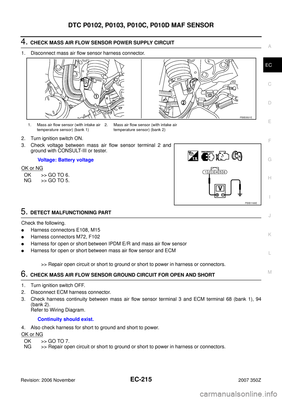
4. CHECK MASS AIR FLOW SENSOR POWER SUPPLY CIRCUIT
1. Disconnect mass air flow sensor harness connector.
2. Turn ignition switch ON.
3. Check voltage between mass air flow sensor terminal 2 and
ground with CONSULT-III or tester.
OK or NG
OK >> GO TO 6.
NG >> GO TO 5.
5. DETECT MALFUNCTIONING PART
Check the following.
�Harness connectors E108, M15
�Harness connectors M72, F102
�Harness for open or short between IPDM E/R and mass air flow sensor
�Harness for open or short between mass air flow sensor and ECM
>> Repair open circuit or short to ground or short to power in harness or connectors.
6. CHECK MASS AIR FLOW SENSOR GROUND CIRCUIT FOR OPEN AND SHORT
1. Turn ignition switch OFF.
2. Disconnect ECM harness connector.
3. Check harness continuity between mass air flow sensor terminal 3 and ECM terminal 68 (bank 1), 94
(bank 2).
Refer to Wiring Diagram.
4. Also check harness for short to ground and short to power.
OK or NG
OK >> GO TO 7.
NG >> Repair open circuit or short to ground or short to power in harness or connectors.
1. Mass air flow sensor (with intake air
temperature sensor) (bank 1)2. Mass air flow sensor (with intake air
temperature sensor) (bank 2)
Voltage: Battery voltage
PBIB3501E
PBIB1168E
Continuity should exist.
Page 230 of 720
EC-230
DTC P0122, P0123, P0227, P0228 TP SENSOR
Revision: 2006 November2007 350Z
DTC Confirmation ProcedureNBS0005X
NOTE:
If DTC Confirmation Procedure has been previously conducted, always turn ignition switch OFF and wait at
least 10 seconds before conducting the next test.
TESTING CONDITION:
Before performing the following procedure, confirm that battery voltage is more than 8V at idle.
WITH CONSULT-III
1. Start engine and let it idle for 1 second.
2. Check DTC.
3. If DTC is detected, go to EC-235, "
Diagnostic Procedure" .
WITH GST
Follow the procedure “WITH CONSULT-III” above.
Page 248 of 720

EC-248
DTC P0130, P0150 A/F SENSOR 1
Revision: 2006 November2007 350Z
DTC P0130, P0150 A/F SENSOR 1PFP:22693
Component DescriptionNBS006U5
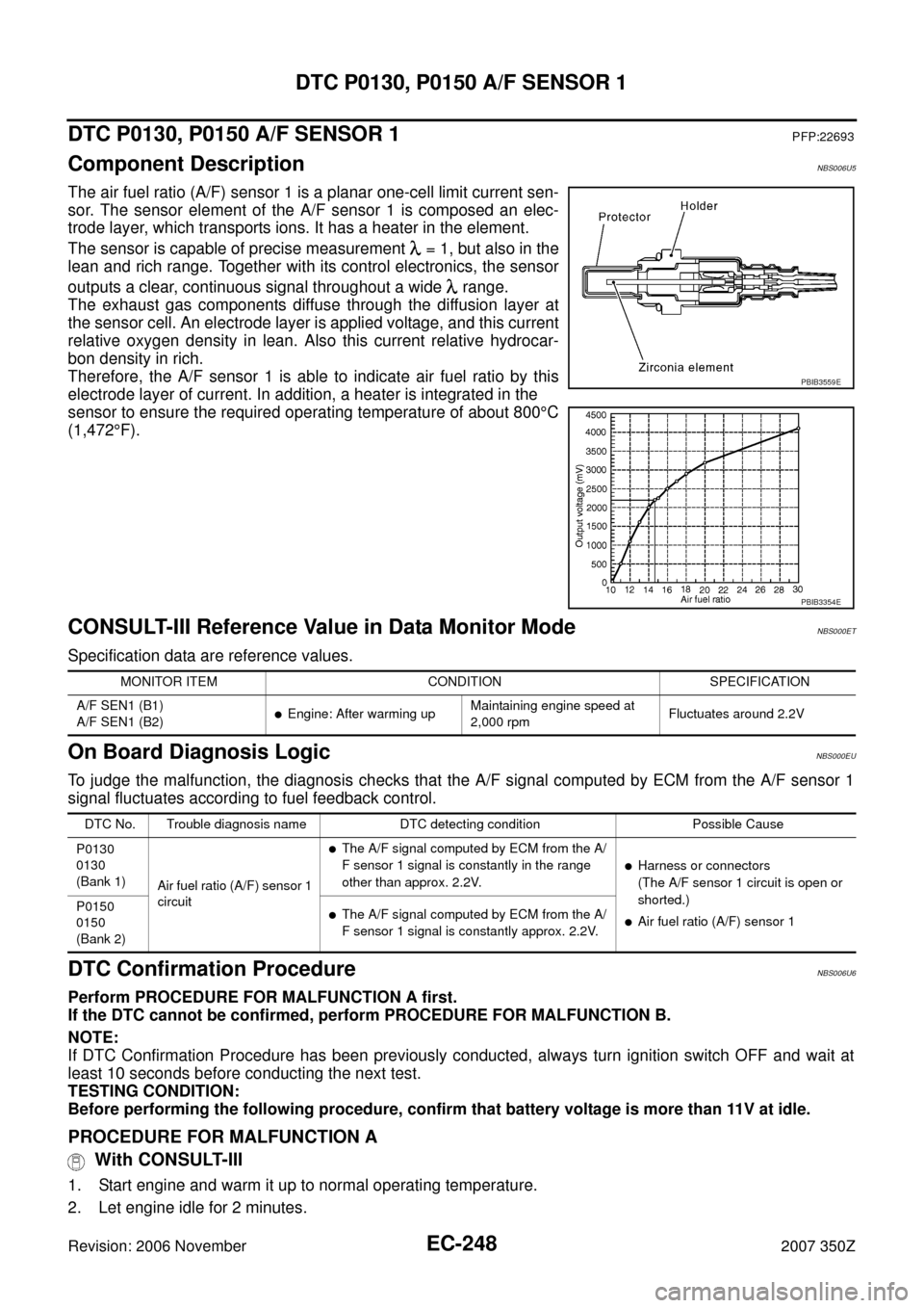
The air fuel ratio (A/F) sensor 1 is a planar one-cell limit current sen-
sor. The sensor element of the A/F sensor 1 is composed an elec-
trode layer, which transports ions. It has a heater in the element.
The sensor is capable of precise measurement = 1, but also in the
lean and rich range. Together with its control electronics, the sensor
outputs a clear, continuous signal throughout a wide range.
The exhaust gas components diffuse through the diffusion layer at
the sensor cell. An electrode layer is applied voltage, and this current
relative oxygen density in lean. Also this current relative hydrocar-
bon density in rich.
Therefore, the A/F sensor 1 is able to indicate air fuel ratio by this
electrode layer of current. In addition, a heater is integrated in the
sensor to ensure the required operating temperature of about 800°C
(1,472°F).
CONSULT-III Reference Value in Data Monitor ModeNBS000ET
Specification data are reference values.
On Board Diagnosis LogicNBS000EU
To judge the malfunction, the diagnosis checks that the A/F signal computed by ECM from the A/F sensor 1
signal fluctuates according to fuel feedback control.
DTC Confirmation ProcedureNBS006U6
Perform PROCEDURE FOR MALFUNCTION A first.
If the DTC cannot be confirmed, perform PROCEDURE FOR MALFUNCTION B.
NOTE:
If DTC Confirmation Procedure has been previously conducted, always turn ignition switch OFF and wait at
least 10 seconds before conducting the next test.
TESTING CONDITION:
Before performing the following procedure, confirm that battery voltage is more than 11V at idle.
PROCEDURE FOR MALFUNCTION A
With CONSULT-III
1. Start engine and warm it up to normal operating temperature.
2. Let engine idle for 2 minutes.
PBIB3559E
PBIB3354E
MONITOR ITEM CONDITION SPECIFICATION
A/F SEN1 (B1)
A/F SEN1 (B2)
�Engine: After warming upMaintaining engine speed at
2,000 rpmFluctuates around 2.2V
DTC No. Trouble diagnosis name DTC detecting condition Possible Cause
P0130
0130
(Bank 1)
Air fuel ratio (A/F) sensor 1
circuit
�The A/F signal computed by ECM from the A/
F sensor 1 signal is constantly in the range
other than approx. 2.2V.
�Harness or connectors
(The A/F sensor 1 circuit is open or
shorted.)
�Air fuel ratio (A/F) sensor 1 P0150
0150
(Bank 2)�The A/F signal computed by ECM from the A/
F sensor 1 signal is constantly approx. 2.2V.
Page 255 of 720
DTC P0130, P0150 A/F SENSOR 1
EC-255
C
D
E
F
G
H
I
J
K
L
MA
EC
Revision: 2006 November2007 350Z
2. CHECK AIR FUEL RATIO (A/F) SENSOR 1 POWER SUPPLY CIRCUIT
1. Disconnect air fuel ratio (A/F) sensor 1 harness connector.
2. Turn ignition switch ON.
3. Check voltage between A/F sensor 1 terminal 4 and ground with
CONSULT-III or tester.
OK or NG
OK >> GO TO 4.
NG >> GO TO 3.
3. DETECT MALFUNCTIONING PART
Check the following.
�Harness connectors E12, F3
�15A fuse
�Harness for open or short between A/F sensor 1 and fuse
>> Repair or replace harness or connectors.
1. A/F sensor 1 (bank 1) harness con-
nector2. A/F sensor 1 (bank 2) harness con-
nector
:Vehicle front
Voltage: Battery voltage
PBIB3516E
PBIB3308E