Page 1039 of 1449

FRONT SUSPENSION -Stabilizer Bar33A-13
Pre-removal Operation
DSteering Wheel and Air Bag Module Assembly
Removal (Refer to GROUP 37A.)
DClock Spring Removal (Refer to GROUP 52B.)
DCrossmember Bar Removal (Refer to P.33A-15.)
DCentermember Removal (Refer to GROUP 32.)
DFront Exhaust Pipe Removal (Refer to GROUP 15.)Post-installation Operation
DFront Exhaust Pipe Installation (Refer to GROUP
15.)
DCentermember Installation (Refer to GROUP 32.)
DCrossmember Bar Installation (Refer to P.33A-15.)
DClock Spring Installation (Refer to GROUP 52B.)
DSteering Wheel and Air Bag Module Assembly
Installation (Refer to GROUP 37A.)
DCheck the Dust Cover for Cracks or Damage by
Pushing it with Finger.
DChecking Steering Wheel Position with Wheels
Straight Ahead
DFront Wheel Alignment Check and Adjustment
(Refer to P.33A-4.)
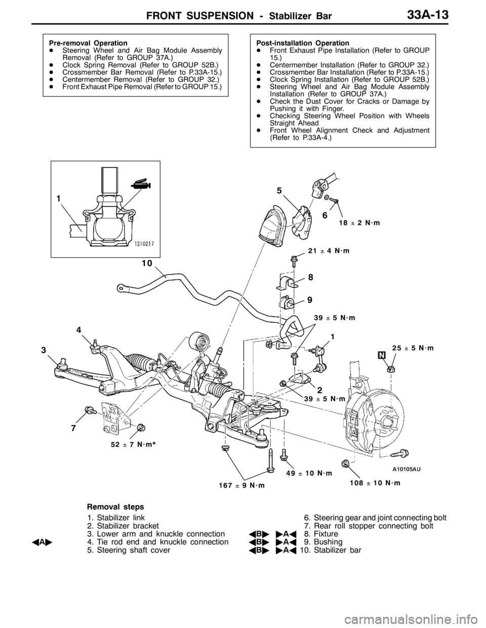
3
4
10
21±4N·m
51
1
2
25±5N·m
18±2N·m
108±10 N·m
52±7N·m*
49±10 N·m
167±9N·m
7
8
9
6
39±5N·m
39±5N·m
Removal steps
1. Stabilizer link
2. Stabilizer bracket
3. Lower arm and knuckle connection
AA"4. Tie rod end and knuckle connection
5. Steering shaft cover6. Steering gear and joint connecting bolt
7. Rear roll stopper connecting bolt
AB""AA8. Fixture
AB""AA9. Bushing
AB""AA10. Stabilizer bar
Page 1049 of 1449

BASIC BRAKE SYSTEM -On-vehicle Service35A-7
ON-VEHICLE SERVICE
BRAKE PEDAL CHECK AND ADJUSTMENT
BRAKE PEDAL HEIGHT
1. Turn up the carpet, etc. under the brake pedal.
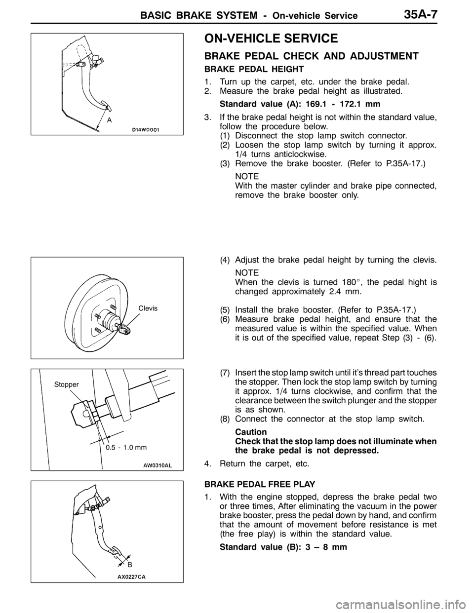
2. Measure the brake pedal height as illustrated.
Standard value (A): 169.1 - 172.1 mm
3. If the brake pedal height is not within the standard value,
follow the procedure below.
(1) Disconnect the stop lamp switch connector.
(2) Loosen the stop lamp switch by turning it approx.
1/4 turns anticlockwise.
(3) Remove the brake booster. (Refer to P.35A-17.)
NOTE
With the master cylinder and brake pipe connected,
remove the brake booster only.
(4) Adjust the brake pedal height by turning the clevis.
NOTE
When the clevis is turned 180_, the pedal hight is
changed approximately 2.4 mm.
(5) Install the brake booster. (Refer to P.35A-17.)
(6) Measure brake pedal height, and ensure that the
measured value is within the specified value. When
it is out of the specified value, repeat Step (3) - (6).
(7) Insert the stop lamp switch until it’s thread part touches
the stopper. Then lock the stop lamp switch by turning
it approx. 1/4 turns clockwise, and confirm that the
clearance between the switch plunger and the stopper
is as shown.
(8) Connect the connector at the stop lamp switch.
Caution
Check that the stop lamp does not illuminate when
the brake pedal is not depressed.
4. Return the carpet, etc.
BRAKE PEDAL FREE PLAY
1. With the engine stopped, depress the brake pedal two
or three times, After eliminating the vacuum in the power
brake booster, press the pedal down by hand, and confirm
that the amount of movement before resistance is met
(the free play) is within the standard value.
Standard value (B):3–8mm
A
Clevis
Stopper
0.5 - 1.0 mm
B
Page 1115 of 1449

37A-1
STEERING
CONTENTS
GENERAL INFORMATION 2..................
SERVICE SPECIFICATIONS 4.................
LUBRICANTS 4..............................
SEALANT 4..................................
SPECIAL TOOLS 4...........................
ON-VEHICLE SERVICE 7.....................
Steering Wheel Free Play Check 7..............
Steering Angle Check 7........................
Tie Rod End Ball Joint Turning Torque Check 7..
Stationary Steering Effort Check 8...............
Checking Steering Wheel Return to Centre 8.....
Drive Belt Tension Check 8.....................Power Steering Fluid Level Check 9.............
Power Steering Fluid Replacement 9.............
Power Steering System Bleeding 9..............
Oil Pump Pressure Test 10.....................
Power Steering Oil Pressure Switch Check 11....
Ball Joint Dust Cover Check 11.................
STEERING WHEEL* 12.......................
STEERING SHAFT* 14.......................
POWER STEERING GEAR BOX AND
LINKAGE* 16................................
POWER STEERING OIL PUMP 29............
POWER STEERING OIL HOSES 30...........
WARNINGS REGARDING SERVICING OF SUPPLEMENTAL RESTRAINT SYSTEM (SRS) EQUIPPED VEHICLES
WARNING!
(1) Improper service or maintenance of any component of the SRS, or any SRS-related component, can lead to personal
injury or death to service personnel (from inadvertent firing of the air bag) or to the driver and passenger (from rendering
the SRS inoperative).
(2) Service or maintenance of any SRS component or SRS-related component must be performed only at an authorized
MITSUBISHI dealer.
(3) MITSUBISHI dealer personnel must thoroughly review this manual, and especially its GROUP 52B - Supplemental
Restraint System (SRS) before beginning any service or maintenance of any component of the SRS or any SRS-related
component.
NOTE
The SRS includes the following components: SRS-ECU, SRS warning lamp, air bag module, clock spring and interconnecting
wiring. Other SRS-related components (that may have to be removed/installed in connection with SRS service or maintenance) are
indicated in the table of contents by an asterisk (*).
Page 1126 of 1449
STEERING -Steering Wheel37A-12
STEERING WHEEL
REMOVAL AND INSTALLATION
Caution:
Before removing the steering wheel and air bag module assembly, refer to GROUP 52B – Service
Precautions and Air Bag Module and Clock Spring.
Post-installation Operation
Checking Steering Wheel Position with Wheels Straight
Ahead
1 2
41±8 N·m
9±2 N·m
9±2 N·m
Removal steps
1. Air bag module assembly
AA"2. Steering wheel
1 250±5 N·m
2
Removal steps
AB"1. Cover
AC"2. Steering wheel and air bag module
assembly
Page 1127 of 1449
STEERING -Steering Wheel37A-13
REMOVAL SERVICE POINTS
AA"STEERING WHEEL REMOVAL
AB"COVER REMOVAL
Insert the special tool from the indicated position to remove
the cover.
NOTE
The special tool can be inserted through the notch behind
the position shown.
AC"STEERING WHEEL AND AIRBAG MODULE
ASSEMBLY REMOVAL
1. By sliding section A of the clock spring connector shown
in the illutration in the arrow direction, disconnect the
connector.
2. Loosen the bolt completely. Then, remove the steering
wheel and airbag module assembly.
NOTE
Use a hexagonal bit socket or a hexagonal wrench having
an effective length of 75 mm or more in the hexagonal
section and the diameter of 8 mm or more.MB990784
MB990784
Clock spring
connector
Steering
wheel
A
Hexagonal
bit socket
Page 1128 of 1449

STEERING -Steering Shaft37A-14
STEERING SHAFT
REMOVAL AND INSTALLATION
Caution:
Before removing clock spring, refer to GROUP 52B – Service Precautions and Air Bag Module
and Clock Spring.
Pre-removal Operation
DSteering Wheel Removal (Refer to P.37A-12.)
DInstrument Under Cover Removal
(Refer to GROUP 52A.)Post-installation Operation
DInstrument Under Cover Installation
(Refer to GROUP 52A.)
DSteering Wheel Installation (Refer to P.37A-12.)
DChecking Steering Wheel Position with Wheels
Straight Ahead
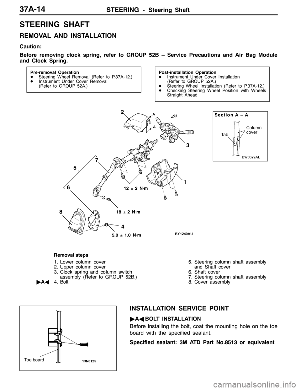
Ta b
Column
cover
2Section A – A
13
4 5
67
A
A
18±2 N·m 12±2 N·m
5.0±1.0 N·m8
Removal steps
1. Lower column cover
2. Upper column cover
3. Clock spring and column switch
assembly (Refer to GROUP 52B.)
"AA4. Bolt5. Steering column shaft assembly
and Shaft cover
6. Shaft cover
7. Steering column shaft assembly
8. Cover assembly
INSTALLATION SERVICE POINT
"AABOLT INSTALLATION
Before installing the bolt, coat the mounting hole on the toe
board with the specified sealant.
Specified sealant: 3M ATD Part No.8513 or equivalent
Toe board
Page 1130 of 1449

STEERING - Power Steering Gear Box and Linkage37A-16
POWER STEERING GEAR BOX AND LINKAGE
REMOVAL AND INSTALLATION
Caution: SRS
Before removing steering gear box, refer to GROUP 52B. Also, put the front wheels in straight-ahead
position. Failure to do so may damage the SRS clock spring and render the SRS air bag inoperative,
which results serious driver injury.
Caution
If the vehicle is equipped with the Brembo disc brake, during maintenance, take care not to contact
the parts or tools to the caliper because the paint of caliper will be scratched. And if there is
brake fluid on the caliper, wipe out quickly.
Pre-removal Operation
DClock Spring Removal (Refer to GROUP 52B.)
DPower Steering Fluid Draining (Refer to P.37A-9.)Post-installation Operation
DClock Spring Installation (Refer to GROUP 52B.)
DPower Steering Fluid Supplying and bleeding
(Refer to P.37A-9.)
DChecking Steering Wheel Position with Wheels
Straight Ahead
17
6
3 4
57±7 N·m5
8
70±10 N·m
2
15±3 N·m
9
10
12±2 N·m 12±2 N·m
70±10 N·m
Removal steps
1. Crossmember
(Refer to GROUP 32.)
DRear roll stopper(Refer to GROUP 32.)
2. Joint cover grommet
3. Return hose
4. Return tube5. O ring
6. Return tube
7. Eye bolt
8. Pressure hose assembly
9. Clamp
10. Steering gear and linkage
Page 1136 of 1449

STEERING - Power Steering Gear Box and Linkage37A-22
DISASSEMBLY SERVICE POINTS
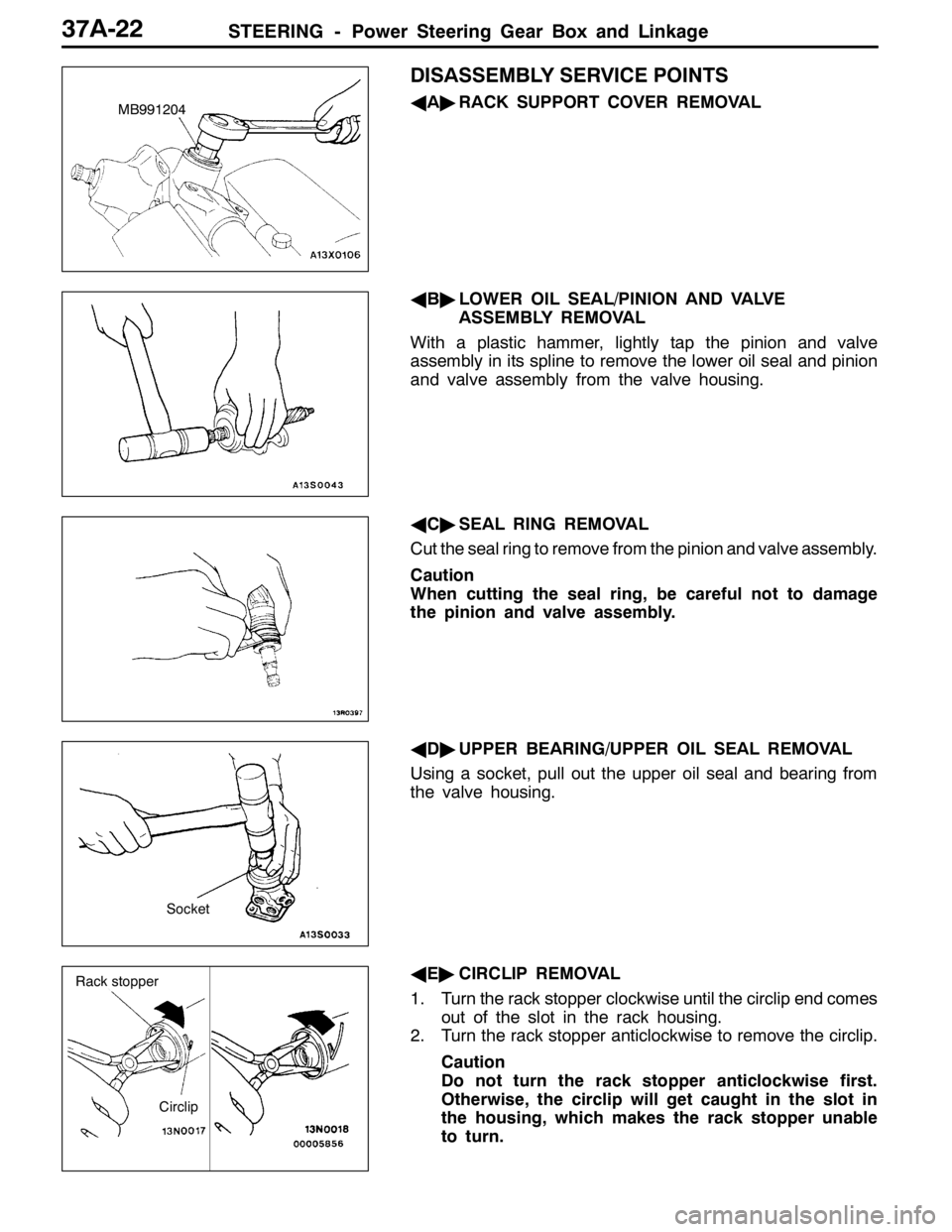
AA"RACK SUPPORT COVER REMOVAL
AB"LOWER OIL SEAL/PINION AND VALVE
ASSEMBLY REMOVAL
With a plastic hammer, lightly tap the pinion and valve
assembly in its spline to remove the lower oil seal and pinion
and valve assembly from the valve housing.
AC"SEAL RING REMOVAL
Cut the seal ring to remove from the pinion and valve assembly.
Caution
When cutting the seal ring, be careful not to damage
the pinion and valve assembly.
AD"UPPER BEARING/UPPER OIL SEAL REMOVAL
Using a socket, pull out the upper oil seal and bearing from
the valve housing.
AE"CIRCLIP REMOVAL
1. Turn the rack stopper clockwise until the circlip end comes
out of the slot in the rack housing.
2. Turn the rack stopper anticlockwise to remove the circlip.
Caution
Do not turn the rack stopper anticlockwise first.
Otherwise, the circlip will get caught in the slot in
the housing, which makes the rack stopper unable
to turn.MB991204
Socket
Circlip
Rack stopper