Page 472 of 1449

ENGINE OVERHAUL -Timing Belt11B-18
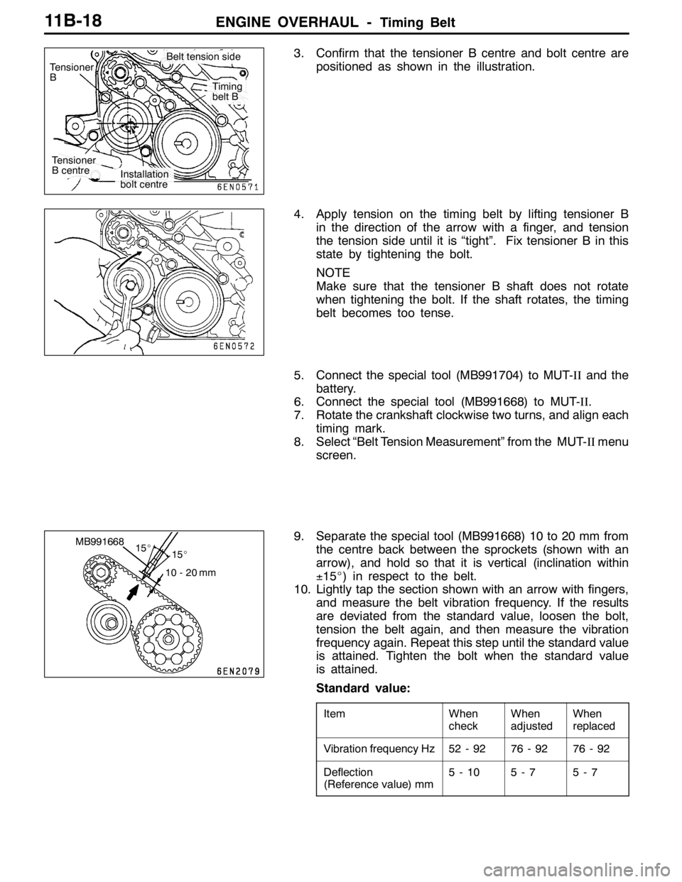
3. Confirm that the tensioner B centre and bolt centre are
positioned as shown in the illustration.
4. Apply tension on the timing belt by lifting tensioner B
in the direction of the arrow with a finger, and tension
the tension side until it is “tight”. Fix tensioner B in this
state by tightening the bolt.
NOTE
Make sure that the tensioner B shaft does not rotate
when tightening the bolt. If the shaft rotates, the timing
belt becomes too tense.
5. Connect the special tool (MB991704) to MUT-IIand the
battery.
6. Connect the special tool (MB991668) to MUT-II.
7. Rotate the crankshaft clockwise two turns, and align each
timing mark.
8. Select “Belt Tension Measurement” from the MUT-IImenu
screen.
9. Separate the special tool (MB991668) 10 to 20 mm from
the centre back between the sprockets (shown with an
arrow), and hold so that it is vertical (inclination within
±15_) in respect to the belt.
10. Lightly tap the section shown with an arrow with fingers,
and measure the belt vibration frequency. If the results
are deviated from the standard value, loosen the bolt,
tension the belt again, and then measure the vibration
frequency again. Repeat this step until the standard value
is attained. Tighten the bolt when the standard value
is attained.
Standard value:
ItemWhen
checkWhen
adjustedWhen
replaced
Vibration frequency Hz52 - 9276 - 9276 - 92
Deflection
(Reference value) mm5-105-75-7
Tensioner
B centre
Installation
bolt centre
Timing
belt B
Belt tension side
Tensioner
B
MB991668
15_ 15_
10 - 20 mm
Page 474 of 1449

ENGINE OVERHAUL -Timing Belt11B-20
"JAOIL PUMP SPROCKET INSTALLATION
1. Stop the rotation of the counter balance shaft in the same
manner as for removal.
2. Install the oil pump sprocket.
3. Apply the minimum required amount of engine oil on the
flange nut seat surface.
4. Tighten the flange nut at the specified torque 54±5
N•m.
"KAAUTO TENSIONER INSTALLATION
1. If the auto tensioner rod is in the extended state, set
it with the following steps.
(1) Set the rod of the auto tensioner into a vice so that
it is straight and not inclined.
(2) Press in the rod gradually with the vice, and align
the rod’s set hole A with the cylinder’s set hole B.
(3) Insert a wire (diameter 1.4 mm) into the set holes.
(4) Remove the auto tensioner from the vice.
2. Install the auto tensioner.
Do not remove the wire until the timing belt has been
installed.
"LATENSIONER PULLEY INSTALLATION
Set the tensioner pulley as shown in the illustration.
"MATIMING BELT INSTALLATION
1. Set the timing mark on the exhaust side camshaft sprocket
so that it is deviated by one tooth in the counterclockwise
direction from the timing mark on the rocker cover.
NOTE
Even if the sprocket and rocker cover timing marks are
aligned, the exhaust camshaft will return in the
counterclockwise direction by the force of the valve spring
and will stabilize at a position deviated by one tooth.
Phillips driver
A
B
Tensioner pulley holes
Timing marks
Page 475 of 1449

ENGINE OVERHAUL -Timing Belt11B-21
2. Align the timing mark of the intake side camshaft sprocket
to the timing mark on the rocker cover.
NOTE
Even when the sprocket and rocker cover timing marks
are aligned, the intake camshaft will rotate slightly in the
clockwise direction by the force of the valve spring and
will stabilize.
3. Shift and set the crankshaft sprocket timing mark by one
tooth in the counterclockwise direction in the same manner
as the exhaust side camshaft sprocket.
4. Align the oil pump sprocket timing marks.
5. When aligning the oil pump sprocket timing marks, remove
the cylinder block plug, and insert an 8 mm shaft diameter
Phillips driver into the plug hole, and confirm that the
driver shaft can be inserted by 60 mm or more. Do not
remove the Phillips driver until the timing belt has been
attached. If the driver shaft contacts the silent shaft and
only enters 20 to 25 mm, rotate the sprocket once, align
the timing marks again, and then confirm that the Phillips
driver can be inserted by 60 mm or more.
6. Remove the Phillips driver, and set the oil pump sprocket
at a position returned by one tooth in the counterclockwise
direction.
7. Attach the timing belt to the exhaust side camshaft
sprocket, and fix with a paper clip at the position shown
in the illustration.
Timing marks
Phillips driverPlug
Timing
marks
Page 476 of 1449

ENGINE OVERHAUL -Timing Belt11B-22
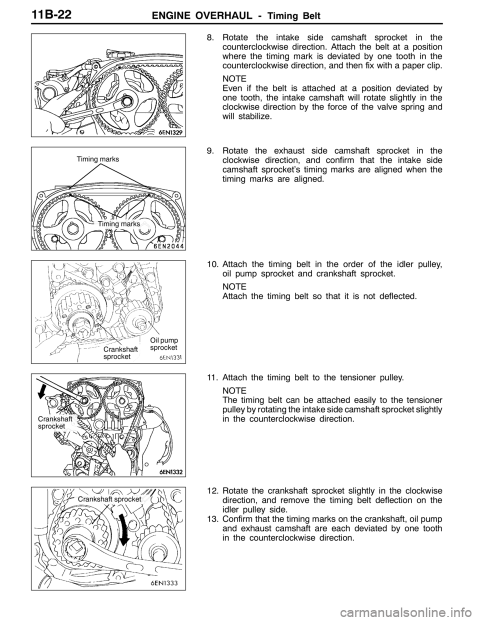
8. Rotate the intake side camshaft sprocket in the
counterclockwise direction. Attach the belt at a position
where the timing mark is deviated by one tooth in the
counterclockwise direction, and then fix with a paper clip.
NOTE
Even if the belt is attached at a position deviated by
one tooth, the intake camshaft will rotate slightly in the
clockwise direction by the force of the valve spring and
will stabilize.
9. Rotate the exhaust side camshaft sprocket in the
clockwise direction, and confirm that the intake side
camshaft sprocket’s timing marks are aligned when the
timing marks are aligned.
10. Attach the timing belt in the order of the idler pulley,
oil pump sprocket and crankshaft sprocket.
NOTE
Attach the timing belt so that it is not deflected.
11. Attach the timing belt to the tensioner pulley.
NOTE
The timing belt can be attached easily to the tensioner
pulley by rotating the intake side camshaft sprocket slightly
in the counterclockwise direction.
12. Rotate the crankshaft sprocket slightly in the clockwise
direction, and remove the timing belt deflection on the
idler pulley side.
13. Confirm that the timing marks on the crankshaft, oil pump
and exhaust camshaft are each deviated by one tooth
in the counterclockwise direction.
Timing marks Timing marks
Crankshaft
sprocketOil pump
sprocket
Crankshaft
sprocket
Crankshaft sprocket
Page 477 of 1449

ENGINE OVERHAUL -Timing Belt11B-23
14. Using the special tool, rotate the tensioner pulley in the
counterclockwise direction to tense the timing belt, and
then fix by temporarily tightening the tensioner fixing bolt.
NOTE
Remove the deflection of the timing belt between the
intake side and exhaust side camshafts.
15. Rotate the crankshaft in the clockwise direction, and set
the timing mark at the No. 1 cylinder compression top
dead centre.
16. Set the special tool, and screw it in until the wire inserted
when the auto tensioner was installed slightly moves.
17. Loosen the tensioner pulley fixing bolt.
Caution
The timing belt will loosen at this time due to the
rotation of the intake and exhaust camshafts, so make
sure that the timing belt does not deviate.
18. Rotate the special tool and torque wrench in the
counterclockwise direction to remove the timing belt
deflection.
19. From that state, return to the position where the torque
wrench scale reads 3.5 N•m, and then tighten the fixing
bolt.
20. Remove the special tool installed in step 16.
21. Rotate the crankshaft two rotations in the clockwise
direction, and let stand for approx. 15 minutes.
22. Confirm whether the wire inserted when the auto tensioner
was installed can be pulled out easily. If it can be removed
easily, the belt tension is appropriate, so remove the wire.
If the auto tensioner rod’s protrusion amount is at the
standard value, the tension is appropriate.
Standard value: 3.8 - 4.5 mm
23. If the wire cannot be pulled out easily, repeat steps 16
to 21, and tense the belt to the appropriate tension.
Caution
When the crankshaft bolt has been rotated in the
counterclockwise direction, always check the crank-
shaft bolt’s tightening torque. If loosen, re-tighten.
MD998767
MD998738
MD998767
Protru-
sion
amount
Page 490 of 1449

ENGINE OVERHAUL -Rocker Arm and Camshaft11B-36
3. Apply sealant on the contact surfaces with the head shown
in the illustration.
Sealant
Specified sealant:
3M
TMAAD Part No. 8672 or equivalent
4. Install the bearing caps onto the cylinder head, and in
two to three steps tighten strongly.
5. Finally, tighten at the specified torque 20±1N•m.
6. Confirm that the rocker arm is correctly installed.
NOTE
Wipe off all excessive sealant.
"DACAMSHAFT OIL SEAL INSTALLATION
Install the oil seal using the special tool.
"EACAM POSITION SENSOR SUPPORT
INSTALLATION
Apply a 3 mm width of form-in-place gasket at the position
shown in the illustration.
Form-in-place gasket
Specified gasket:
Mitsubishi Genuine Part No. MD970389 or
equivalent
"FACAM POSITION SENSING CYLINDER
INSTALLATION
1. Set the exhaust camshaft at the No. 1 compression top
dead centre.
NOTE
The shaft will rotate slightly in the counterclockwise
direction by the force of the exhaust valve spring.
2. Install the cam position sensing cylinder’s vane (small)
and vane (large) at the positions shown in the illustration.
MD998713
Vane (small)
Cam position
sensorVane (large)
Page 744 of 1449

ENGINE ELECTRICAL -Charging System16-12
REMOVAL SERVICE POINTS
AA"DELIVERY PIPE, INJECTOR, AND FUEL
PRESSURE REGULATOR ASSEMBLY REMOVAL
After loosening the installed parts, set the related parts
aside to make some space for removing the alternator.
AB"DRIVE BELT REMOVAL
Due to the adoption of the Serpentine drive system with
the auto-tensioner, the following operation is required:
1. Insert the 12.7sq. spinner handle into the tool hole of
the auto-tensioner and rotate it counterclockwise until
the auto-tensioner reaches to the stopper.
2. Align hole A with hole B for fixing by inserting the L-shaped
hexagon wrench, then remove the drive belt.
Caution
When the drive belt is reused, use a chalk to
indicate an arrow of rotation direction on the
back of the belt so that it can be re-assembled in
the same direction as before.
AC"ALTERNATOR REMOVAL
Push up the engine with a garage jack to the top and
remove the alternator upward from the engine room.
Hole A
L-shaped
hexagon
wrench
Hole B
Page 794 of 1449

CLUTCH -On-Vehicle Service21A-4
3. If the height of the clutch pedal is outside the standard
value, loosen the setting nut to adjust the pedal height
to the standard value.
Caution
Do not push in the master cylinder push rod at this
time, otherwise the clutch will not operate properly.
4. After completing the adjustments, confirm that the clutch
pedal free play (measured at the face of the pedal pad)
and the distance between the clutch pedal (the face of
the pedal pad) and the clutch pedal stopper or toeboard
when the clutch is disengaged are within the standard
value ranges.
Standard value (C): 4 - 13 mm
Standard value (D):
114.3 mm or more
100 mm or more
5. If the clutch pedal free play and the distance between
the clutch pedal and the clutch pedal stopper or toeboard
when the clutch is disengaged do not agree with the
standard values, it is probably the result of either air in
the hydraulic system or a faulty master cylinder, clutch
cylinder or clutch. Bleed the air, or disassemble and inspect
the master cylinder, clutch cylinder or clutch.
6. Turn back the carpet, etc.
BLEEDING
Specified fluid: Brake fluid DOT 3 or DOT 4
Caution
Use the specified brake fluid. Avoid using a mixture
of the specified fluid and other fluid.
CLUTCH PEDAL POSITION SWITCH
ADJUSTMENT
1. Adjust the clutch pedal. (Refer to P. 21A-3).
2. Disconnect the connector from clutch pedal position
switch.
3. Loosen the clutch pedal position switch by rotating approx.
quarter turn to counterclockwise.
4. Fix the clutch pedal in full stroke.
Clutch pedal Setting nut
13±2 N·m
Clutch pedal clevis pin play
C
Clutch
pedal
stopper
D D