2007 MITSUBISHI LANCER EVOLUTION clock
[x] Cancel search: clockPage 795 of 1449

CLUTCH -On-Vehicle Service/Clutch Pedal21A-5
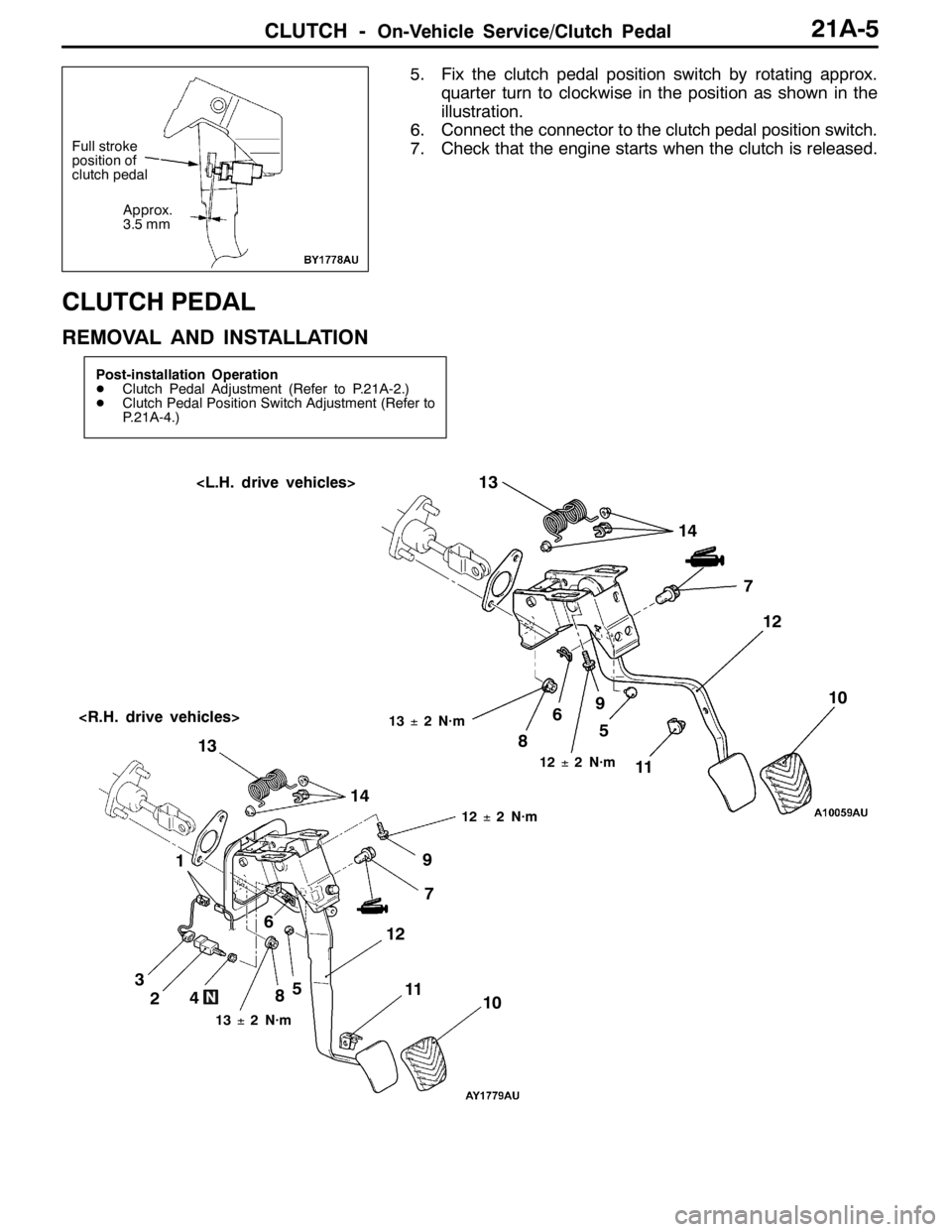
5. Fix the clutch pedal position switch by rotating approx.
quarter turn to clockwise in the position as shown in the
illustration.
6. Connect the connector to the clutch pedal position switch.
7. Check that the engine starts when the clutch is released.
CLUTCH PEDAL
REMOVAL AND INSTALLATION
Post-installation Operation
DClutch Pedal Adjustment (Refer to P.21A-2.)
DClutch Pedal Position Switch Adjustment (Refer to
P.21A-4.)
6713±2 N·m
1
12±2 N·m
8
11
2459
12±2 N·m
67
13±2 N·m
10 8
12 13
3145 910
1112 13
14
Full stroke
position of
clutch pedal
Approx.
3.5 mm
Page 810 of 1449

22A-2
MANUAL
TRANSMISSION
CONTENTS
GENERAL 3.................................
Outline of Changes 3...........................
GENERAL INFORMATION 3..................
SERVICE SPECIFICATION 3..................
LUBRICANTS 3..............................
SPECIAL TOOLS 4...........................
TROUBLESHOOTING
ON-VEHICLE SERVICE 40....................
Transmission Oil Check 40......................
Transmission Oil Replacement 40................
Transfer Oil Check 40..........................
Transfer Oil Replacement 40....................
Fluid Check
Bleeding
Hydraulic Pressure Check
Wheel Speed Sensor Output Voltage
Measurement
TRANSMISSION CONTROL* 46...............
TRANSFER ASSEMBLY 49...................
TRANSMISSION ASSEMBLY 52...............
4WD-ECU
SENSOR, SWITCH AND RELAY
AYC> 56.....................................
HYDRAULIC UNIT Refer to GROUP27B.......
WARNING REGARDING SERVICING OF SUPPLEMENTAL RESTRAINT SYSTEM (SRS) EQUIPPED VEHICLES
WARNING!
(1) Improper service or maintenance of any component of the SRS, or any SRS-related component, can lead to personal
injury or death to service personnel (from inadvertent firing of the air bag) or to driver and passenger (from rendering
the SRS inoperative).
(2) Service or maintenance of any SRS component or SRS-related component must be performed only at an authorized
MITSUBISHI dealer.
(3) MITSUBISHI dealer personnel must thoroughly review this manual, and especially its GROUP 52B - Supplemental
Restraint System (SRS) before beginning any service or maintenance of any component of the SRS or any SRS-related
component.
NOTE
The SRS includes the following components: SRS-ECU, SRS warning lamp, air bag module, clock spring, and interconnecting
wiring. Other SRS-related components (that may have to be removed/installed in connection with SRS service or maintenance) are
indicated in the table of contents by an asterisk (*).
Page 864 of 1449

MANUAL TRANSMISSION -Sensor, Switch and Relay
SENSOR, SWITCH AND RELAY
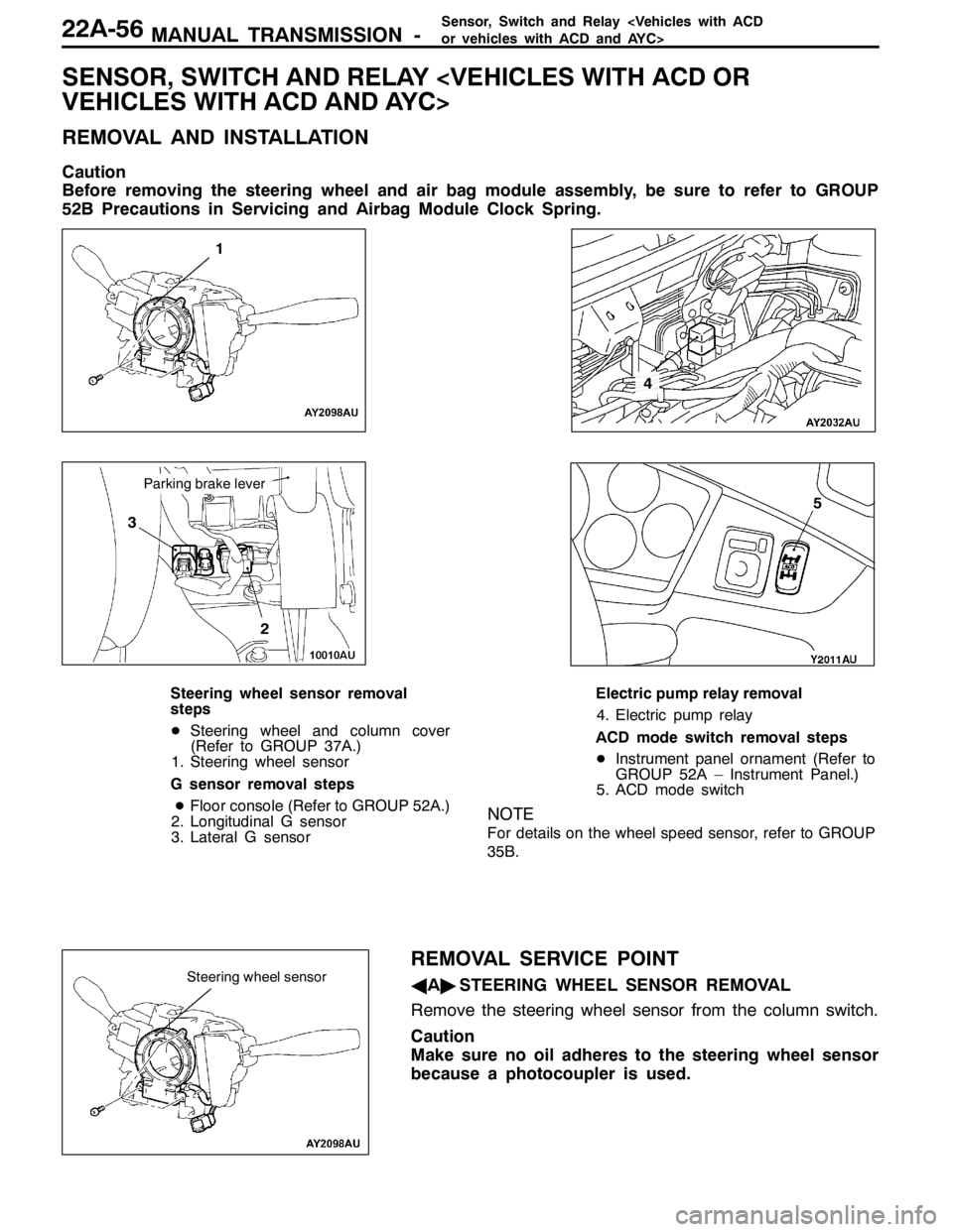
REMOVAL AND INSTALLATION
Caution
Before removing the steering wheel and air bag module assembly, be sure to refer to GROUP
52B Precautions in Servicing and Airbag Module Clock Spring.
1
3
2
4
5
Parking brake lever
Steering wheel sensor removal
steps
DSteering wheel and column cover
(Refer to GROUP 37A.)
1. Steering wheel sensor
G sensor removal steps
DFloor console (Refer to GROUP 52A.)
2. Longitudinal G sensor
3. Lateral G sensorElectric pump relay removal
4. Electric pump relay
ACD mode switch removal steps
DInstrument panel ornament (Refer to
GROUP 52A – Instrument Panel.)
5. ACD mode switch
NOTE
For details on the wheel speed sensor, refer to GROUP
35B.
REMOVAL SERVICE POINT
AA"STEERING WHEEL SENSOR REMOVAL
Remove the steering wheel sensor from the column switch.
Caution
Make sure no oil adheres to the steering wheel sensor
because a photocoupler is used.Steering wheel sensor
Page 962 of 1449

REAR AXLE -On-vehicle Service27B-16
DATA LIST REFERENCE TABLE
For check, refer to GROUP 22.
ACTUATOR TEST REFERENCE TABLE
For check, refer to GROUP 22.
CHECK AT 4WD-ECU TERMINALS
For check, refer to GROUP 22.
ON-VEHICLE SERVICE
REAR AXLE TOTAL BACKLASH CHECK
1. Park the vehicle on a flat, level surface.
2. Move the transmission control lever to the neutral position.
Apply the parking brake. Raise the vehicle on a jack.
3. Turn the companion flange clockwise as far as it will go.
Make the mating mark on the dust cover of the companion
flange and on the differential carrier.
4. Turn the companion flange anti-clockwise as far as it
will go, and measure the amount of distance the mating
marks moved.
Limit: 6 mm
5. If the backlash exceeds the limit value, replace the
differential carrier assembly.
GEAR OIL LEVEL CHECK
1. Remove the filler plug.
2. Check that the gear oil level is within the specified range
from the bottom end of the filler plug hole.
3. If the gear oil level exceeds the standard value, add the
specified gear oil up to the bottom end of the filler plug
hole.
Specified gear oil:
Hypoid gear oil
MITSUBISHI Genuine Gear Oil Part No. 8149630
EX, CASTROL HYPOY LS (GL-5, SAE 90),
SHELL-LSD (GL-5, SAE 80W - 90) or equivalent
4. Fit the filler plug and tighten it to the specified torque.
Tightening torque: 49±9 N·m
Mating marks
Upper
limit
Lower
limit
Gear oil
8mm
Page 966 of 1449

REAR AXLE -On-vehicle Service27B-20
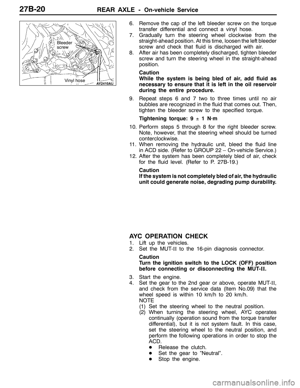
6. Remove the cap of the left bleeder screw on the torque
transfer differential and connect a vinyl hose.
7. Gradually turn the steering wheel clockwise from the
straight-ahead position. At this time, loosen the left bleeder
screw and check that fluid is discharged with air.
8. After air has been completely discharged, tighten bleeder
screw and turn the steering wheel in the straight-ahead
position.
Caution
While the system is being bled of air, add fluid as
necessary to ensure that it is left in the oil reservoir
during the entire procedure.
9. Repeat steps 6 and 7 two to three times until no air
bubbles are recognized in the fluid that comes out. Then,
tighten the bleeder screw to the specified torque.
Tightening torque: 9±1 N·m
10. Perform steps 5 through 8 for the right bleeder screw.
Note, however, that the steering wheel should be turned
conterclockwise.
11. When removing the hydraulic unit, bleed the fluid line
in ACD side. (Refer to GROUP 22 – On-vehicle Service.)
12. After the system has been completely bled of air, check
for the fluid level. (Refer to P. 27B-19.)
Caution
If the system is not completely bled of air, the hydraulic
unit could generate noise, degrading pump durability.
AYC OPERATION CHECK
1. Lift up the vehicles.
2. Set the MUT-IIto the 16-pin diagnosis connector.
Caution
Turn the ignition switch to the LOCK (OFF) position
before connecting or disconnecting the MUT-II.
3. Start the engine.
4. Set the gear to the 2nd gear or above, operate MUT-II,
and check from the service data (Item No.09) that the
wheel speed is within 10 km/h to 20 km/h.
NOTE
(1) Set the steering wheel to the neutral position.
(2) When turning the steering wheel, AYC operates
continually (operation sound from the torque transfer
differential), but it is not system fault. In this case,
set the steering wheel to the neutral position, and
perform the following operations in order to stop the
ACD.
DRelease the clutch.
DSet the gear to ”Neutral”.
DStop the engine.
Bleeder
screw
Vinyl hose
Page 1015 of 1449

32-1
POWER PLANT
MOUNT
CONTENTS
GENERAL INFORMATION 2..................
SPECIAL TOOL 3............................
ENGINE MOUNTING 4........................TRANSMISSION MOUNTING 5................
ENGINE ROLL STOPPER, CENTERMEMBER
6 ............................................
CROSSMEMBER* 8..........................
WARNING REGARDING SERVICING OF SUPPLEMENTAL RESTRAINT SYSTEM (SRS) EQUIPPED VEHICLES
WARNING!
(1) Improper service or maintenance of any component of the SRS, or any SRS-related component, can lead to personal
injury or death to service personnel (from inadvertent firing of the air bag) or to driver and passenger (from rendering
the SRS inoperative).
(2) Service or maintenance of any SRS component or SRS-related component must be performed only at an authorized
MITSUBISHI dealer.
(3) MITSUBISHI dealer personnel must thoroughly review this manual, and especially its GROUP 52B - Supplemental
Restraint System (SRS) before beginning any service or maintenance of any component of the SRS or any SRS-related
component.
NOTE
The SRS includes the following components: SRS-ECU, SRS warning lamp, air bag module, clock spring, and interconnecting
wiring. Other SRS-related components (that may have to be removed/installed in connection with SRS service or maintenance) are
indicated in the table of contents by an asterisk (*).
Page 1022 of 1449

POWER PLANT MOUNT - Crossmember32-8
CROSSMEMBER
REMOVAL AND INSTALLATION
Caution
1. Before removing the steering wheel and air bag module assembly, always refer to GROUP
52B - Service Precautions, Air bag Module and Clock Spring. Also, set the front wheels so
that they are facing straight forward, and remove the ignition key. If you fail to do this, the
SRS clock spring will be damaged, causing the SRS air bag to be inoperative and serious
injury.
2. *
1: Indicates parts which should be initially tightened, and then fully tightened after placing
the vehicle horizontally and loading the full weight of the engine on the vehicle body.
3. *
2: Indicates parts which should be temporarily tightened, and then fully tightened with the
vehicle on the ground in the unladen condition.
Caution
If the vehicle is equipped the Brembo disc brake, during maintenance, take care not to contact
the parts or tools to the caliper because the paint of caliper will be scratched.
Pre-removal Operations
DUnder Cover Removal
(Refer to GROUP 51 - Front Bumper.)
DCentermember, Crossmember Bar Removal
(Refer to P.32-6.)
DFront Exhaust Pipe Removal
(Refer to GROUP 15.)
DSteering Wheel Air Bag Module Assembly Removal
(Refer to GROUP 37A.)
DPower Steering Fluid Draining
(Refer to GROUP 37A - On-vehicle Service.)Post-installation Operations
DCentermember, Crossmember Bar Installation
(Refer to P.32-6.)
DFront Exhaust Pipe Installation
(Refer to GROUP 15.)
DSteering Wheel Air Bag Module Assembly
Installation (Refer to GROUP 37A.)
DPower Steering Fluid Supplying
(Refer to GROUP 37A - On-vehicle Service.)
DPower Steering Fluid Line Bleeding
(Refer to GROUP 37A - On-vehicle Service.)
DPress the dust cover with a finger to check whether
the dust cover is cracked or damaged.
DChecking Steering Wheel Position with Wheels
Straight Ahead
DFront Wheel Alignment Check and Adjustment
(Refer to GROUP 37A - On-vehicle Service.)
DUnder Cover Installation
(Refer to GROUP 51 - Front Bumper.)
Page 1038 of 1449

FRONT SUSPENSION -Lower Arm Assembly/Stabilizer Bar33A-12
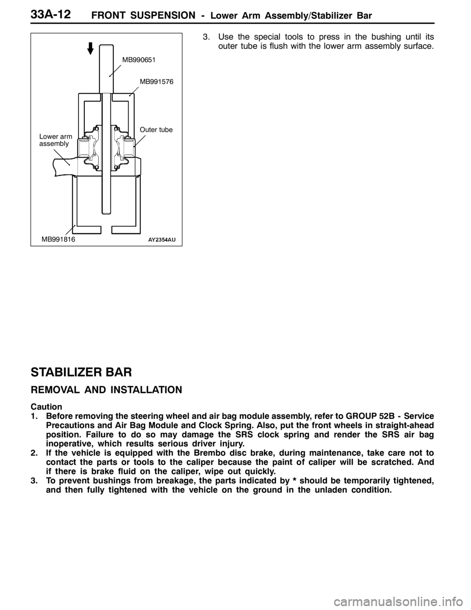
3. Use the special tools to press in the bushing until its
outer tube is flush with the lower arm assembly surface.
STABILIZER BAR
REMOVAL AND INSTALLATION
Caution
1. Before removing the steering wheel and air bag module assembly, refer to GROUP 52B - Service
Precautions and Air Bag Module and Clock Spring. Also, put the front wheels in straight-ahead
position. Failure to do so may damage the SRS clock spring and render the SRS air bag
inoperative, which results serious driver injury.
2. If the vehicle is equipped with the Brembo disc brake, during maintenance, take care not to
contact the parts or tools to the caliper because the paint of caliper will be scratched. And
if there is brake fluid on the caliper, wipe out quickly.
3. To prevent bushings from breakage, the parts indicated by * should be temporarily tightened,
and then fully tightened with the vehicle on the ground in the unladen condition.
Lower arm
assembly
MB990651
MB991576
MB991816
Outer tube