2007 MITSUBISHI LANCER EVOLUTION clock
[x] Cancel search: clockPage 413 of 1449

ENGINE -On-vehicle Service11A-7
ON-VEHICLE SERVICE
DRIVE BELT TENSION CHECK
1. Check that the indicator marking of the auto-tensioner
is within the range as shown in the illustration A of the
tensioner bracket.
Caution
Inspection must be carried out after turning the
crankshaft clockwise for more than once.
2. If the marking is outside the range as shown in the
illustration A, replace the drive belt.
NOTE
Due to the adoption of the auto-tensioner, no adjustment
for belt tension is required.
AUTO-TENSIONER CHECK
1. Check that the driver belt stays within the width of the
pulley of the auto-tensioner after turning off the engine
at idle.
2. Remove the drive belt.(Refer to P.11C-15.)
3. Use the 12.7sq. spinner handle and etc. to check that
the auto-tensioner is not stuck by turning it in both
directions.
4. If there is any abnormality in the above - mentioned 1
or 3, replace the auto-tensioner.
5. Install the drive belt.(Refer to P.11C-15.)
To determine whether the auto-tensioner is acceptable can
be done by checking the drive belt tension.
1. Use the following procedure to check the drive belt tension.
(1) Connect the special tool (MB991668) to the MUT-II.
(2) Connect the MUT-IIto the diagnosis connector.
Caution
Connection and disconnection of the MUT-IImust
be carried out after turning the ignition switch
to the “LOCK” (OFF) position.
(3) Turn the ignition switch to the “ON” position and select
“Belt Tension Measurement” from the menu screen.
Indicator
marking
A
Page 422 of 1449

ENGINE -Crankshaft Pulley/Camshaft and Camshaft Oil Seal11A-16
REMOVAL SERVICE POINT
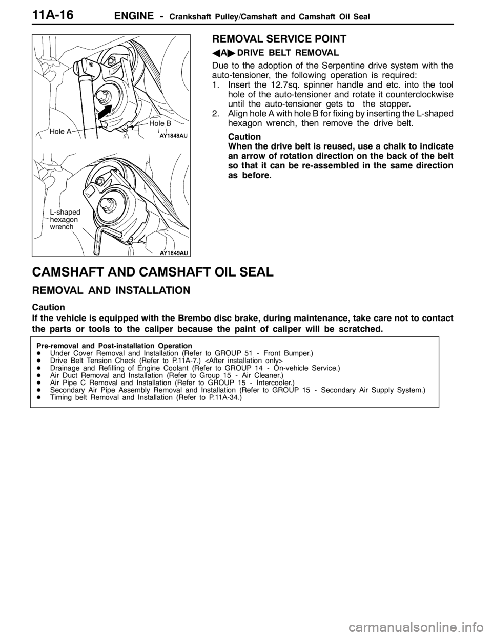
AA"DRIVE BELT REMOVAL
Due to the adoption of the Serpentine drive system with the
auto-tensioner, the following operation is required:
1. Insert the 12.7sq. spinner handle and etc. into the tool
hole of the auto-tensioner and rotate it counterclockwise
until the auto-tensioner gets to the stopper.
2. Align hole A with hole B for fixing by inserting the L-shaped
hexagon wrench, then remove the drive belt.
Caution
When the drive belt is reused, use a chalk to indicate
an arrow of rotation direction on the back of the belt
so that it can be re-assembled in the same direction
as before.
CAMSHAFT AND CAMSHAFT OIL SEAL
REMOVAL AND INSTALLATION
Caution
If the vehicle is equipped with the Brembo disc brake, during maintenance, take care not to contact
the parts or tools to the caliper because the paint of caliper will be scratched.
Pre-removal and Post-installation Operation
DUnder Cover Removal and Installation (Refer to GROUP 51 - Front Bumper.)
DDrive Belt Tension Check (Refer to P.11A-7.)
DDrainage and Refilling of Engine Coolant (Refer to GROUP 14 - On-vehicle Service.)
DAir Duct Removal and Installation (Refer to Group 15 - Air Cleaner.)
DAir Pipe C Removal and Installation (Refer to GROUP 15 - Intercooler.)
DSecondary Air Pipe Assembly Removal and Installation (Refer to GROUP 15 - Secondary Air Supply System.)
DTiming belt Removal and Installation (Refer to P.11A-34.)
Hole A
L-shaped
hexagon
wrench
Hole B
Page 428 of 1449

ENGINE -Camshaft and Camshaft Oil Seal11A-22
"FACAMSHAFT POSITION SENSOR SUPPORT
INSTALLATION
1. Remove sealant remained on the camshaft position
sensor support.
2. Apply sealant to the flange of the camshaft position sensor
support and install to the cylinder head.
Specified sealant:
MITSUBISHI GENUINE PART MD970389 or
equivalent
3. Tighten the camshaft position sensor support mounting
bolt to the specified torque.
Tightening Torque: 14±1 N·m
"GACAMSHAFT POSITION SENSING CYLINDER
INSTALLATION
1. Set the dowel pin of the exhaust camshaft to the position
(No.1cylinder at compression TDC) as shown in the
illustration.
NOTE
Use the force of the exhaust valve spring to rotate
counterclockwise.
2. Install the vane (small) of the camshaft position sensing
cylinder at an angle of approximately 45 degrees to the
position of the dowel pin of the exhaust camshaft.
3. Tighten the camshaft position sensing cylinder mounting
bolt to the specified torque.
Tightening Torque: 22±4 N·m
"HARADIATOR UPPER HOSE CONNECTION
1. Insert the radiator upper hose to the convex part of the
water outlet fitting.
2. Make the mating marks on the upper hose and the hose
clamp for installation.
"IAROCKER COVER GASKET INSTALLATION
1. Remove sealant remained on the rocker cover.
2. Apply sealant to the positions (4 areas) of the lower side of
the rocker cover as shown in the illustration.
Specified sealant:
MITSUBISHI GENUINE PART MD970389 or
equivalent
3. Install the rocker cover gasket to the rocker cover.
ø3 mm
Dowel Pin
Vane (small)
Approximately 45_
Vane (large)
Page 441 of 1449

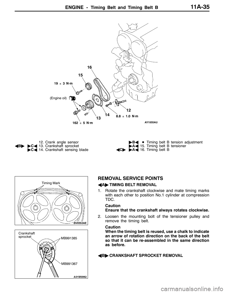
ENGINE -Timing Belt and Timing Belt B11A-35
12
1314 1516
8.8±1.0 N·m
162±5 N·m 19±3 N·m
(Engine oil)
12. Crank angle sensor
AB""CA13. Crankshaft sprocket
"CA14. Crankshaft sensing blade"BADTiming belt B tension adjustment
"AA15. Timing belt B tensioner
AC""AA16. Timing belt B
REMOVAL SERVICE POINTS
AA"TIMING BELT REMOVAL
1. Rotate the crankshaft clockwise and mate timing marks
with each other to position No.1 cylinder at compression
TDC.
Caution
Ensure that the crankshaft always rotates clockwise.
2. Loosen the mounting bolt of the tensioner pulley and
remove the timing belt.
Caution
When the timing belt is reused, use a chalk to indicate
an arrow of rotation direction on the back of the belt
so that it can be re-assembled in the same direction
as before.
AB"CRANKSHAFT SPROCKET REMOVALTiming Mark
MB991367
Crankshaft
sprocket
MB991385
Page 443 of 1449

ENGINE -Timing Belt and Timing Belt B11A-37
(1) Connect the special tool (MB991668) to the MUT-II.
(2) Connect the special tool (MB991704) to the MUT-II
and the battery.
(3) Rotate the crankshaft clockwise for two rounds to
position No.1 cylinder at compression TDC and check
that timing marks of each sprocket are aligned with
each other.
(4) Select “Belt Tension Measurement” from the menu
screen of the MUT-II.
(5) Hold the special tool (MB991668) to the middle of
the belt between sprockets (at the place indicated
by the arrow) as shown in the illustration about 10
- 20 mm away from the rear surface of the belt and
so that it is perpendicular to the belt (within an angle
of±15_).
(6) Gently tap the middle of the belt between sprockets
(the place indicated by the arrow) with your finger
as shown in the illustration and check that the vibration
frequency of the belt is within the standard value.
Caution
1) If strong gusts of wind blow against the
microphone or if there are any loud sources
of noise nearby, the values measured by the
microphone may not correspond to actual
values.
2) If the microphone is touching the belt while
the measurement is being made, the values
measured by the microphone may not
correspond to actual values.
Apply a force of approx.100N to the middle (arrow part)
of pulley shown in the figure, and check that the deflection
is within the standard value.
3. If it is outside the standard value, re-adjust belt tension.
MB991668
10 - 20 mm
15_
15_
Gently tap with
your finger
Deflection
Approx.
100 N
Page 446 of 1449

ENGINE -Timing Belt and Timing Belt B11A-40
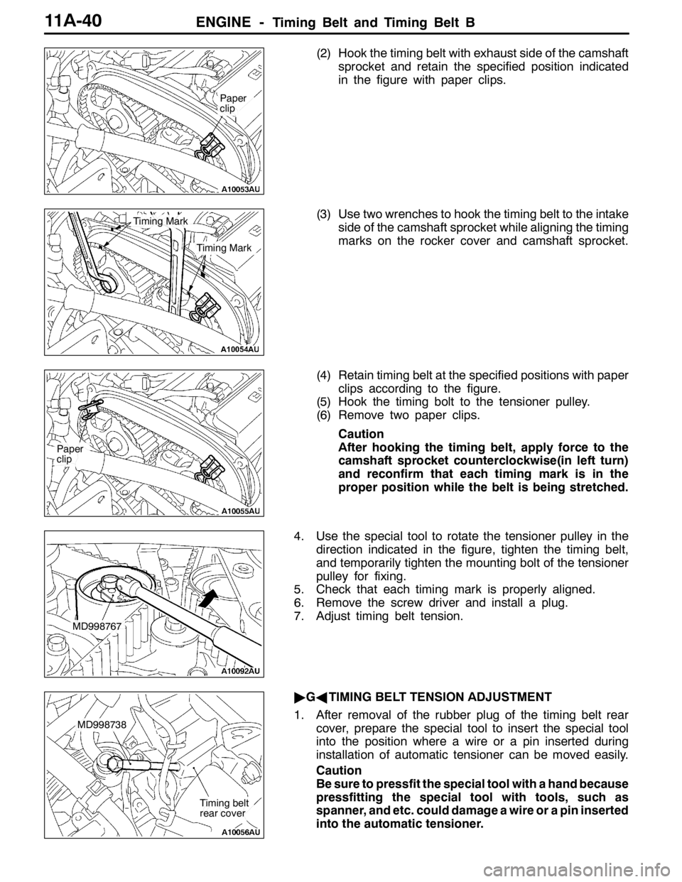
(2) Hook the timing belt with exhaust side of the camshaft
sprocket and retain the specified position indicated
in the figure with paper clips.
(3) Use two wrenches to hook the timing belt to the intake
side of the camshaft sprocket while aligning the timing
marks on the rocker cover and camshaft sprocket.
(4) Retain timing belt at the specified positions with paper
clips according to the figure.
(5) Hook the timing bolt to the tensioner pulley.
(6) Remove two paper clips.
Caution
After hooking the timing belt, apply force to the
camshaft sprocket counterclockwise(in left turn)
and reconfirm that each timing mark is in the
proper position while the belt is being stretched.
4. Use the special tool to rotate the tensioner pulley in the
direction indicated in the figure, tighten the timing belt,
and temporarily tighten the mounting bolt of the tensioner
pulley for fixing.
5. Check that each timing mark is properly aligned.
6. Remove the screw driver and install a plug.
7. Adjust timing belt tension.
"GATIMING BELT TENSION ADJUSTMENT
1. After removal of the rubber plug of the timing belt rear
cover, prepare the special tool to insert the special tool
into the position where a wire or a pin inserted during
installation of automatic tensioner can be moved easily.
Caution
Be sure to pressfit the special tool with a hand because
pressfitting the special tool with tools, such as
spanner, and etc. could damage a wire or a pin inserted
into the automatic tensioner.
Paper
clip
Timing Mark
Timing Mark
Paper
clip
MD998767
MD998738
Timing belt
rear cover
Page 447 of 1449

ENGINE -Timing Belt and Timing Belt B11A-41
2. Rotate the crankshaft counterclockwise for 1/4 round.
3. Rotate the crankshaft clockwise and mate timing marks
with each other to position No.1 cylinder at compression
TDC.
4. Loosen the temporarily tightened tensioner pulley
mounting bolt.
5. Use the special tool and torque wrench to apply tension
torque (3.5 N��m) to the timing belt in the direction indicated
in the figure and tighten the tensioner pulley mounting bolt
to the specified torque.
Tightening Torque: 48±5 N·m
Caution
Be careful not to let the tensioner pulley rotate together
when tightening the mounting bolt. If the tensioner
rotates together, belt tension becomes too loose.
6. Remove a wire or a pin inserted during installation of
the automatic tensioner.
7. Remove the special tool installed in the above - mentioned
1 with a hand.
8. Rotate the crankshaft clockwise for two rounds and leave
it alone for approximately 15 minutes.
9. Insert the removed wire or pin in the above - mentioned
6 again to check that it can be removed easily.
If either wire or pin can be removed easily, the timing
belt tension is correct and remove a wire or a pin. Then,
check that projection of the automatic tensioner rod is
within the standard value.
Standard value (A): 3.8 - 4.5 mm
10. If a wire or a pin cannot be easily removed, repeat the
above-mentioned operations 1 - 8 to obtain the correct
timing belt tension.
11. Check that timing marks of each sprocket are aligned
with each other.
Caution
After turning the crankshaft bolt counterclockwise,
always check the tightening torque of the crankshaft
bolt and tighten it again if it becomes loose.
MD998767
A
Page 452 of 1449

ENGINE -Engine Assembly11A-46
REMOVAL SERVICE POINTS
AA"DRIVE BELT REMOVAL
Due to the adoption of the Serpentine drive system with the
auto-tensioner, the following operation is required:
1. Insert the 12.7sq. spinner handle into the tool hole of
the auto-tensioner and rotate it counterclockwise until
the auto-tensioner reaches to the stopper.
2. Align hole A with hole B for fixing by inserting the L
shaped-hexagon wrench, then remove the drive belt.
Caution
When the drive belt is reused, use a chalk to indicate
an arrow of rotation direction on the back of the belt
so that it can be re-assembled in the same direction
as before.
AB"POWER STEERING OIL PUMP, BRACKET AND
OIL RESERVOIR ASSEMBLY / A/C COMPRESSOR
REMOVAL
Remove the power steering oil pump, bracket, oil reservoir
and A/C compressor with the hose attached from the bracket.
NOTE
Tie the removed oil pump and A/C compressor with a rope
and set aside where they cannot hinder the removal of the
engine assembly.
AC"ENGINE MOUNTING BRACKET AND STOPPER
ASSEMBLY REMOVAL
1. Support the engine with a garage jack.
2. Remove special tool (MZ203827).
(Tool used for removal of transmission assembly)
3. Hold the engine assembly with a chain block.
4. Support the engine oil pan with a garage jack via a block
of wood cut without applying the weight of the engine
and remove the engine mounting bracket and stopper
assembly.
Bore A
L-shaped
hexagon
wrench
Bore B
MZ203827
MB991453
MB991453