2007 ISUZU KB P190 width
[x] Cancel search: widthPage 3006 of 6020
Engine Mechanical – V6 Page 6A1–229
Page 6A1–229
NOTE
• Clean any remaining lapping compound from
the valve and seat with solvent and
compressed air prior to final assembly.
• If fitting new valves, do not lap the valves
under any condition.
7 After obtaining the correct valve seat width in the cylinder head, measure the valve stem height, refer to Valve
Stem Height Measurement Pr ocedure in this Section.
8 If the valve stem height is acceptabl e, test the seats for concentricity, refer to Valve-to-Seat Concentricity
Measurement Procedure in this Section.
Valve Stem Height Measurement Procedure
CAUTION
To determine the valve stem height
measurement, measure from the valve
spring seat to the valve spring retainer.
1 Install the valve into the valve guide.
2 Ensure the valve is seated to the valve seat.
3 Install the valve stem oil seal.
4 Install the valve spring retainer and valve stem keys.
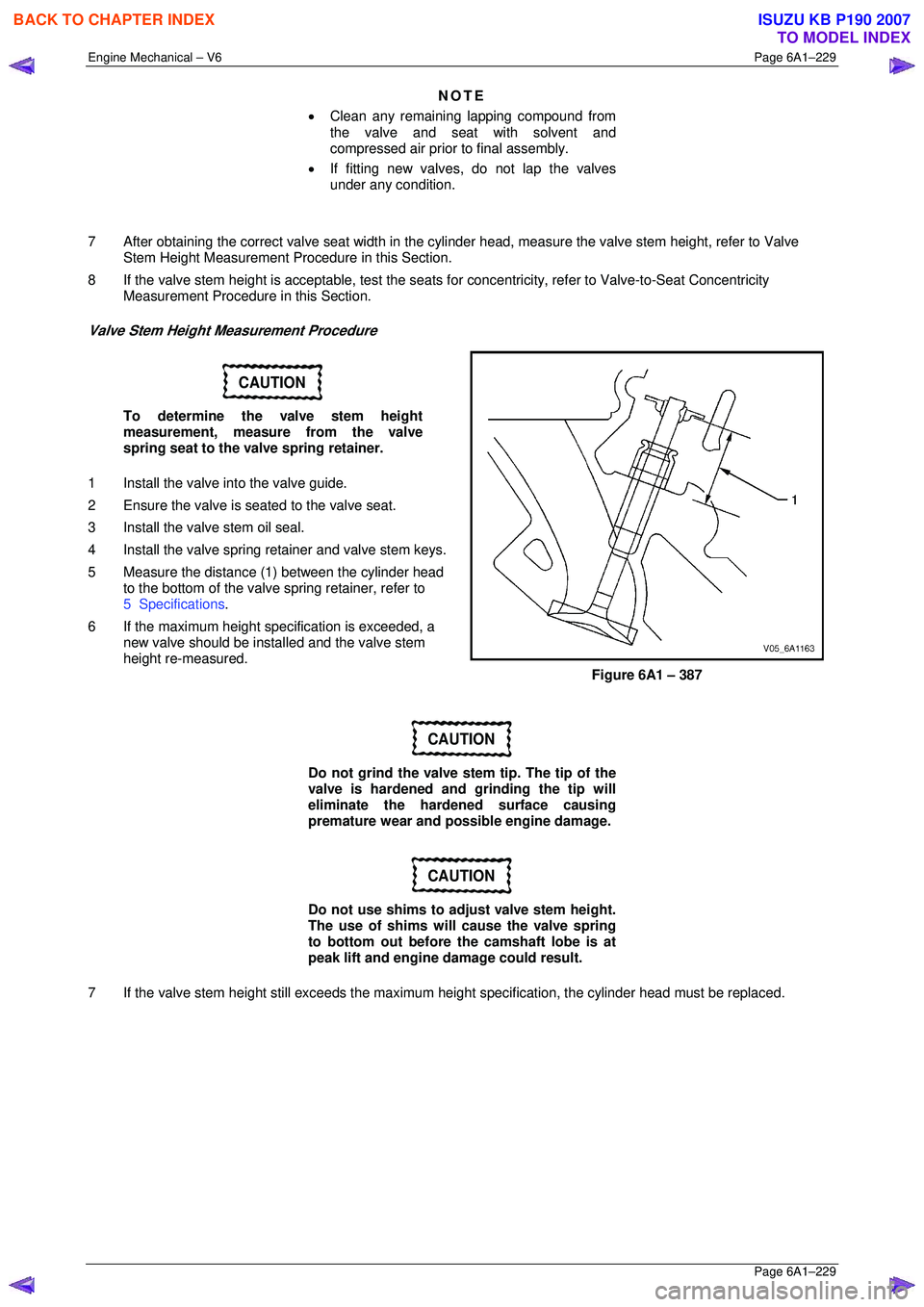
5 Measure the distance (1 ) between the cylinder head
to the bottom of the valve spring retainer, refer to
5 Specifications .
6 If the maximum height spec ification is exceeded, a
new valve should be installed and the valve stem
height re-measured.
Figure 6A1 – 387
CAUTION
Do not grind the valve stem tip. The tip of the
valve is hardened and grinding the tip will
eliminate the hardened surface causing
premature wear and possible engine damage.
CAUTION
Do not use shims to adjust valve stem height.
The use of shims will cause the valve spring
to bottom out before the camshaft lobe is at
peak lift and engine damage could result.
7 If the valve stem height still exceeds the maximum height specification, the cylinder head must be replaced.
BACK TO CHAPTER INDEX
TO MODEL INDEX
ISUZU KB P190 2007
Page 3042 of 6020
Engine Mechanical – V6 Page 6A1–265
Page 6A1–265
4.5 Pistons, Pins, Rings, Connecting Rods
and Big-end Bearings
Remove
1 Remove the engine assembly, refer to 4.1 Engine .
2 Remove both cylinder head assemblies, refer to 3.22 Cylinder Head Assembly.
3 Remove the oil pan assembly, refer to 4.2 Oil Pan and Oil Pump Suction Pipe Assembly .
4 Mark the top of the piston being remo ved to identify its specific bore.
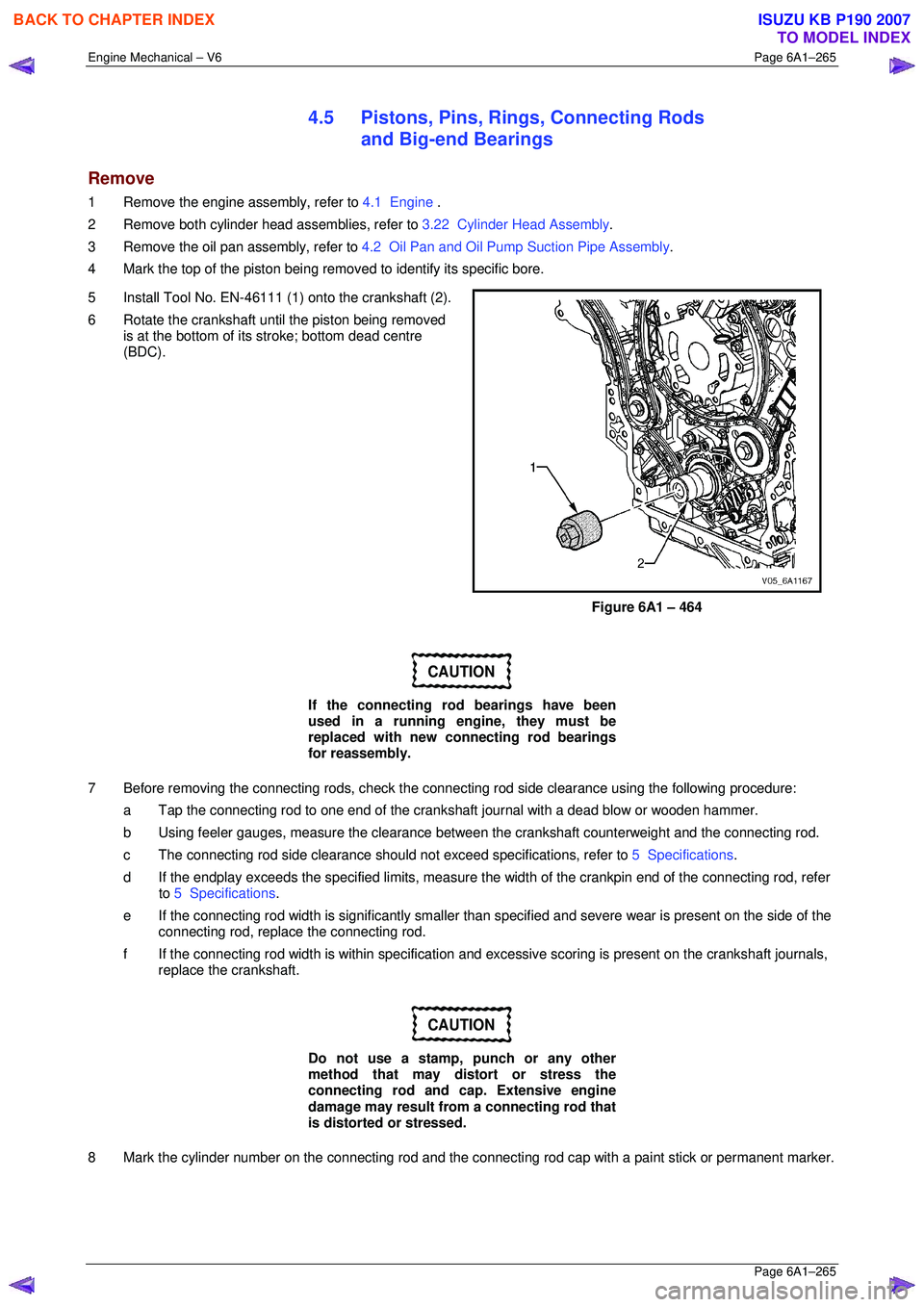
5 Install Tool No. EN-46111 (1) onto the crankshaft (2).
6 Rotate the crankshaft until the piston being removed is at the bottom of its stroke; bottom dead centre
(BDC).
Figure 6A1 – 464
CAUTION
If the connecting rod bearings have been
used in a running engine, they must be
replaced with new connecting rod bearings
for reassembly.
7 Before removing the connecting rods, check the connec ting rod side clearance using the following procedure:
a Tap the connecting rod to one end of the cranks haft journal with a dead blow or wooden hammer.
b Using feeler gauges, measure the clearance between the crankshaft counterweight and the connecting rod.
c The connecting rod side clearance should not exceed specifications, refer to 5 Specifications.
d If the endplay exceeds the specified limits, measure the width of the crankpin end of the connecting rod, refer
to 5 Specifications .
e If the connecting rod width is significantly smaller than specified and severe wear is present on the side of the
connecting rod, replac e the connecting rod.
f If the connecting rod width is within specification and excessive scoring is present on the crankshaft journals,
replace the crankshaft.
CAUTION
Do not use a stamp, punch or any other
method that may distort or stress the
connecting rod and cap. Extensive engine
damage may result from a connecting rod that
is distorted or stressed.
8 Mark the cylinder number on the connec ting rod and the connecting rod cap with a paint stick or permanent marker.
BACK TO CHAPTER INDEX
TO MODEL INDEX
ISUZU KB P190 2007
Page 3047 of 6020
Engine Mechanical – V6 Page 6A1–270
Page 6A1–270
Piston Measurement
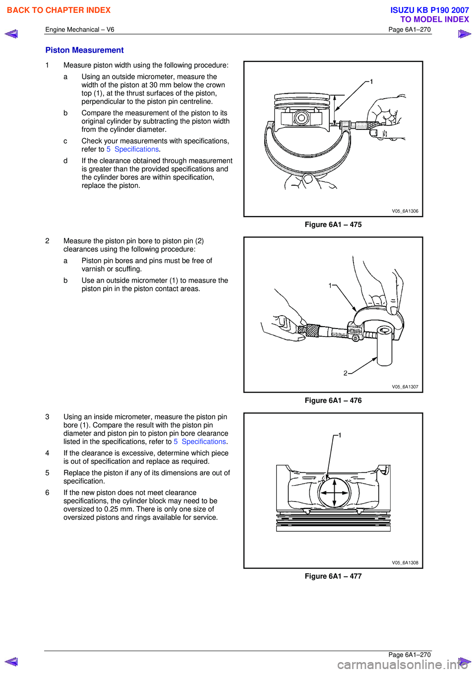
1 Measure piston width using the following procedure:
a Using an outside micr ometer, measure the
width of the piston at 30 mm below the crown
top (1), at the thrust surfaces of the piston,
perpendicular to the piston pin centreline.
b Compare the measurement of the piston to its
original cylinder by subtracting the piston width
from the cylinder diameter.
c Check your measurements with specifications, refer to 5 Specifications .
d If the clearance obtai ned through measurement
is greater than the prov ided specifications and
the cylinder bores are wi thin specification,
replace the piston.
Figure 6A1 – 475
2 Measure the piston pin bore to piston pin (2) clearances using the following procedure:
a Piston pin bores and pins must be free of varnish or scuffing.
b Use an outside micrometer (1) to measure the
piston pin in the piston contact areas.
Figure 6A1 – 476
3 Using an inside micrometer , measure the piston pin
bore (1). Compare the resu lt with the piston pin
diameter and piston pin to piston pin bore clearance
listed in the specifications, refer to 5 Specifications.
4 If the clearance is excessive, determine which piece is out of specification and replace as required.
5 Replace the piston if any of its dimensions are out of
specification.
6 If the new piston does not meet clearance specifications, the cylinder block may need to be
oversized to 0.25 mm. There is only one size of
oversized pistons and rings available for service.
Figure 6A1 – 477
BACK TO CHAPTER INDEX
TO MODEL INDEX
ISUZU KB P190 2007
Page 3056 of 6020
Engine Mechanical – V6 Page 6A1–279
Page 6A1–279
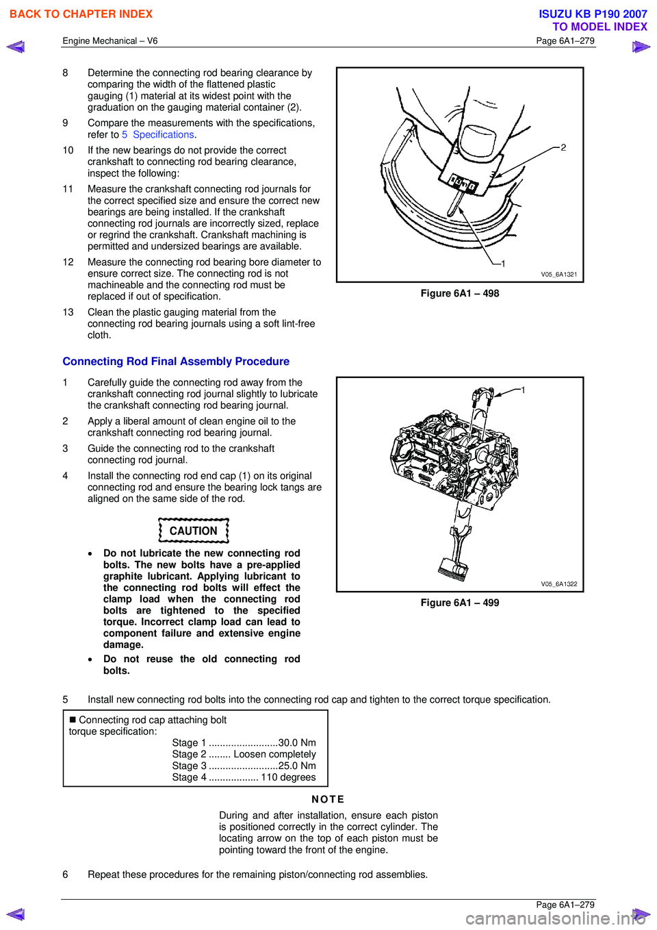
8 Determine the connecting rod bearing clearance by
comparing the width of the flattened plastic
gauging (1) material at its widest point with the
graduation on the gauging mate rial container (2).
9 Compare the measurements with the specifications,
refer to 5 Specifications .
10 If the new bearings do not provide the correct crankshaft to connecting rod bearing clearance,
inspect the following:
11 Measure the crankshaft connecting rod journals for the correct specified size and ensure the correct new
bearings are being installed. If the crankshaft
connecting rod journals are in correctly sized, replace
or regrind the crankshaft. Crankshaft machining is
permitted and undersized bearings are available.
12 Measure the connecting rod bearing bore diameter to
ensure correct size. The connecting rod is not
machineable and the connecting rod must be
replaced if out of specification.
13 Clean the plastic gauging material from the connecting rod bearing journals using a soft lint-free
cloth.
Figure 6A1 – 498
Connecting Rod Final Assembly Procedure
1 Carefully guide the connecting rod away from the crankshaft connecting rod journal slightly to lubricate
the crankshaft connecting rod bearing journal.
2 Apply a liberal amount of clean engine oil to the crankshaft connecting rod bearing journal.
3 Guide the connecting rod to the crankshaft connecting rod journal.
4 Install the connecting rod end cap (1) on its original
connecting rod and ensure t he bearing lock tangs are
aligned on the same side of the rod.
CAUTION
• Do not lubricate the new connecting rod
bolts. The new bolts have a pre-applied
graphite lubricant. Applying lubricant to
the connecting rod bolts will effect the
clamp load when the connecting rod
bolts are tightened to the specified
torque. Incorrect clamp load can lead to
component failure and extensive engine
damage.
• Do not reuse the old connecting rod
bolts.
Figure 6A1 – 499
5 Install new connecting rod bolts into the connecting r od cap and tighten to the correct torque specification.
�„ Connecting rod cap attaching bolt
torque specification:
Stage 1 .........................30.0 Nm
Stage 2 ........Loosen completely
Stage 3 .........................25.0 Nm
Stage 4 ..................110 degrees
NOTE
During and after installation, ensure each piston
is positioned correctly in the correct cylinder. The
locating arrow on the top of each piston must be
pointing toward the front of the engine.
6 Repeat these procedures for the rema ining piston/connecting rod assemblies.
BACK TO CHAPTER INDEX
TO MODEL INDEX
ISUZU KB P190 2007
Page 3064 of 6020
Engine Mechanical – V6 Page 6A1–287
Page 6A1–287
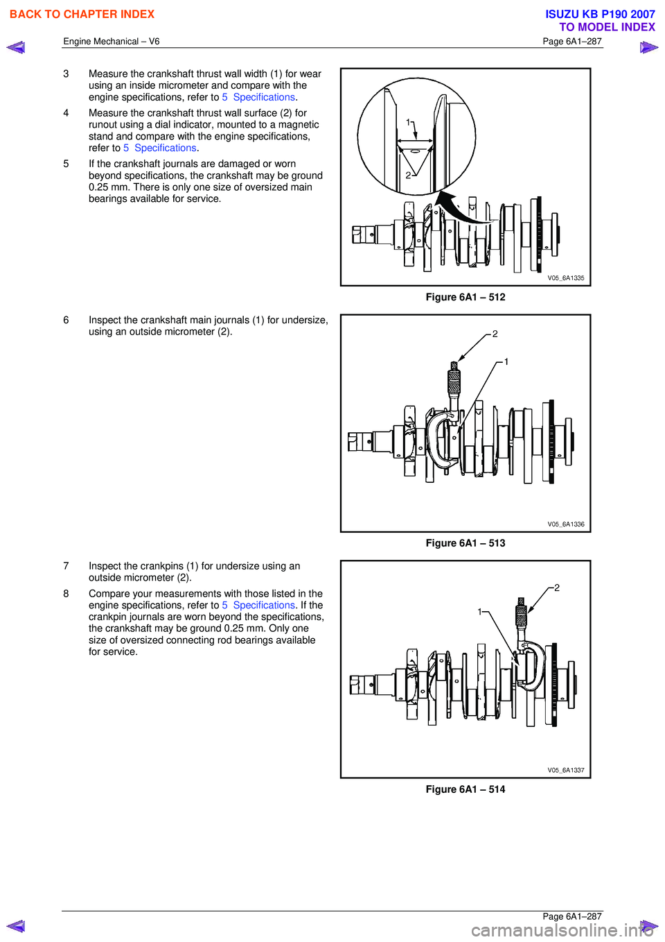
3 Measure the crankshaft thrust wall width (1) for wear
using an inside micrometer and compare with the
engine specifications, refer to 5 Specifications.
4 Measure the crankshaft thrust wall surface (2) for runout using a dial indica tor, mounted to a magnetic
stand and compare with t he engine specifications,
refer to 5 Specifications .
5 If the crankshaft journals are damaged or worn beyond specifications, t he crankshaft may be ground
0.25 mm. There is only one size of oversized main
bearings available for service.
Figure 6A1 – 512
6 Inspect the crankshaft main journals (1) for undersize, using an outside micrometer (2).
Figure 6A1 – 513
7 Inspect the crankpins (1) for undersize using an outside micrometer (2).
8 Compare your measurements with those listed in the
engine specifications, refer to 5 Specifications. If the
crankpin journals are worn beyond the specifications,
the crankshaft may be ground 0.25 mm. Only one
size of oversized connecting rod bearings available
for service.
Figure 6A1 – 514
BACK TO CHAPTER INDEX
TO MODEL INDEX
ISUZU KB P190 2007
Page 3067 of 6020
Engine Mechanical – V6 Page 6A1–290
Page 6A1–290
NOTE
Do not rotate the crankshaft.
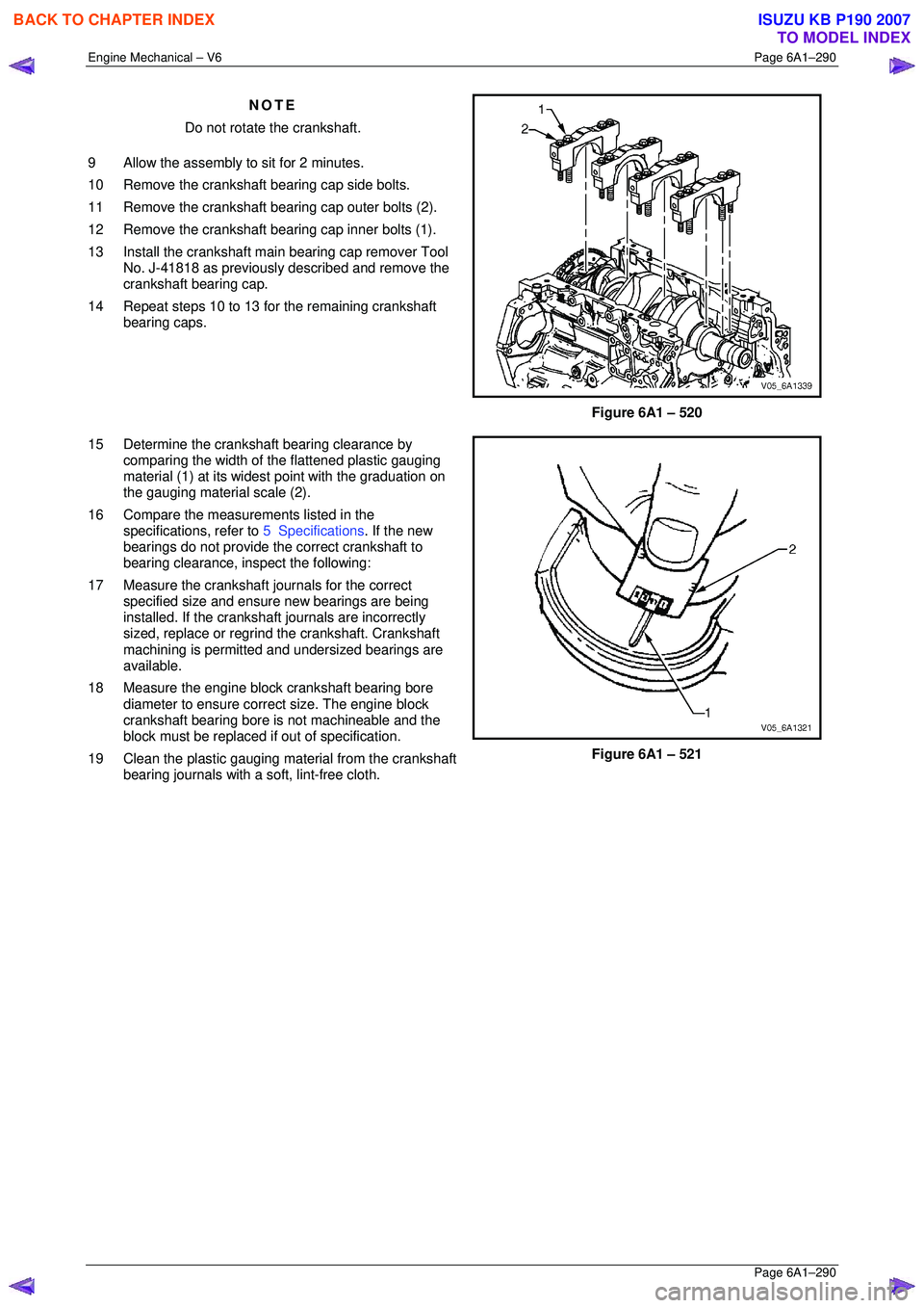
9 Allow the assembly to sit for 2 minutes.
10 Remove the crankshaft bearing cap side bolts.
11 Remove the crankshaft bearing cap outer bolts (2).
12 Remove the crankshaft bearing cap inner bolts (1).
13 Install the crankshaft main bearing cap remover Tool No. J-41818 as previously described and remove the
crankshaft bearing cap.
14 Repeat steps 10 to 13 for the remaining crankshaft bearing caps.
Figure 6A1 – 520
15 Determine the crankshaft bearing clearance by comparing the width of the flattened plastic gauging
material (1) at its widest point with the graduation on
the gauging material scale (2).
16 Compare the measur ements listed in the
specifications, refer to 5 Specifications. If the new
bearings do not provide the correct crankshaft to
bearing clearance, inspect the following:
17 Measure the crankshaft journals for the correct specified size and ensure new bearings are being
installed. If the crankshaft journals are incorrectly
sized, replace or regrind the crankshaft. Crankshaft
machining is permitted and undersized bearings are
available.
18 Measure the engine block crankshaft bearing bore diameter to ensure correct size. The engine block
crankshaft bearing bore is not machineable and the
block must be replaced if out of specification.
19 Clean the plastic gauging material from the crankshaft bearing journals with a soft, lint-free cloth.
Figure 6A1 – 521
BACK TO CHAPTER INDEX
TO MODEL INDEX
ISUZU KB P190 2007
Page 3124 of 6020
Engine Mechanical – V6 Page 6A1–347
Page 6A1–347
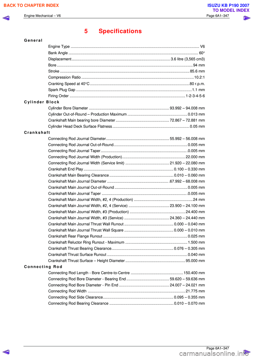
5 Specifications
General
Engine Type .................................................................................................................... .... V6
Bank An gle ..................................................................................................................... .... 60°
Displacement ............................................................................................ 3.6 litre (3,565 cm3)
Bore ........................................................................................................................... .... 94 mm
Stroke ......................................................................................................................... 85.6 mm
Compression Ratio......................................................................................................... 10. 2:1
Cranking Speed at 40 °C .............................................................................................80 r.p.m.
Spark Plug Gap ............................................................................................................ 1.1 mm
Firing Order ............................................................................................................ 1- 2-3-4-5-6
Cylinder Block
Cylinder Bore Diame ter ........................................................................... 93.992 – 94.008 mm
Cylinder Out-of-Round – Pr oduction Maximum ........................................................ 0.013 mm
Crankshaft Main bearing bor e Diameter .................................................. 72. 867 – 72.881 mm
Cylinder Head Deck Surf ace Flatness ........................................................................ 0. 05 mm
Crankshaft
Connecting Rod Journal Diameter........................................................... 55. 992 – 56.008 mm
Connecting Rod Journa l Out-of-Round..................................................................... 0.005 mm
Connecting Rod Jour nal Taper................................................................................ .0. 005 mm
Connecting Rod Journal Width (Production)........................................................... 22.000 mm
Connecting Rod Journal Width (Service limit)......................................... 21. 920 – 22.080 mm
Crankshaft End Pl ay .................................................................................... 0.100 – 0.330 mm
Crankshaft Main Bearing Clearance ............................................................ 0.010 – 0.060 mm
Crankshaft Main Journal Diameter......................................................... .67. 992 – 68.008 mm
Crankshaft Main Journa l Out-of-Round .................................................................... 0.005 mm
Crankshaft Main Journal Taper ............................................................................... .0. 005 mm
Crankshaft Main Journal Width, #2, 4 (Pr oduction)....................................................... 24 mm
Crankshaft Main Journal Width, #2, 4 (Service)...................................... 23. 900 – 24.100 mm
Crankshaft Main Journal Wi dth, #3 (Production) .................................................... 24.400 mm
Crankshaft Main Journal Width, #3 (Service).......................................... 24. 360 – 24.440 mm
Crankshaft Main Journal Thru st Wall Runout.............................................. 0.
000 – 0.040 mm
Crankshaft Main Journal Thru st Wall Square.............................................. 0. 000 – 0.010 mm
Crankshaft Rear Fl ange Runout............................................................................... 0. 025 mm
Crankshaft Reluctor Ring Ru nout - Maximum .......................................................... 1.500 mm
Crankshaft Thrust Bearin g Clearance.......................................................... 0. 076 – 0.305 mm
Crankshaft Thrust Su rface Runout........................................................................... 0. 040 mm
Crankshaft Thrust Surface – Height Diameter ........................................................ 95.000 mm
Connecting Rod
Connecting Rod Length - Bore Centre-to-Centre ................................................. 150.400 mm
Connecting Rod Bore Diameter - Bearing End........................................ 59. 620 – 59.636 mm
Connecting Rod Bore Diamet er - Pin End............................................... 24. 007 – 24.021 mm
Connecting Rod Width ........................................................................................... 21.775 mm
Connecting Rod Side Cl earance.................................................................. 0.095 – 0.355 mm
Connecting Rod Bearing Clearance ............................................................ 0.010 – 0.070 mm
BACK TO CHAPTER INDEX
TO MODEL INDEX
ISUZU KB P190 2007
Page 3125 of 6020
Engine Mechanical – V6 Page 6A1–348
Page 6A1–348
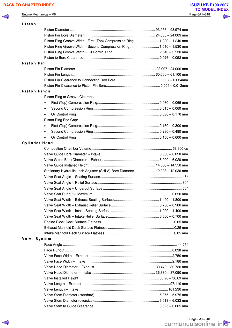
Piston
Piston Diameter ....................................................................................... 93. 956 – 93.974 mm
Piston Pin Bore Diame ter ........................................................................ 24.005 – 24.009 mm
Piston Ring Groove Width - First (Top) Compression Ring ......................... 1.220 – 1.240 mm
Piston Ring Groove Width - Second Compression Ring.............................. 1. 510 – 1.530 mm
Piston Ring Groove Width - Oil Control Ring ............................................... 2. 510 – 2.530 mm
Piston to Bore Clear ance ............................................................................. 0.026 – 0.052 mm
Piston Pin
Piston Pin Diamet er .................................................................................. 23.997 - 24.000 mm
Piston Pin Length ..................................................................................... 60. 600 – 61.100 mm
Piston Pin Clearance to Connec ting Rod Bore............................................. 0. 007 – 0.024mm
Piston Pin Clearance to Pist on Pin Bore....................................................... 0. 004 – 0.012mm
Piston Rings
Piston Ring to Groove Clearance:
• First (Top) Compression Ring............................................................... 0. 030 – 0.065 mm
• Second Compression Ring ................................................................... 0.015 – 0.060 mm
• Oil Control Ring .................................................................................... 0. 030 – 0.170 mm
Piston Ring End Gap:
• First (Top) Compression Ring............................................................... 0. 150 – 0.300 mm
• Second Compression Ring ................................................................... 0.280 – 0.480 mm
• Oil Control Ring .................................................................................... 0. 150 – 0.600 mm
Cylinder Head
Combustion Chambe r Volume.................................................................................. 53. 600 cc
Valve Guide Bore Diameter – Intake ........................................................... 6.000 – 6.020 mm
Valve Guide Bore Diameter – Exhaust ........................................................ 6.000 – 6.020 mm
Valve Guide Installed Height................................................................... 14. 050 – 14.550 mm
Stationary Hydraulic Lash Adjuster (S HLA) Bore Diameter .....................12.008 – 12.030 mm
Valve Seat Angle – Seating Surface ................................................................................... 45 °
Valve Seat Angle – Relief Surface...................................................................................... 30 °
Valve Seat Angle – Un dercut Surface ................................................................................ 60 °
Valve Seat Runout – Maximum................................................................................ 0. 050 mm
Valve Seat Width – Exhaust S eating Surface.............................................. 1. 400 – 1.800 mm
Valve Seat Width – Exhaust Re lief Surface................................................. 0. 700 – 0.900 mm
Valve Seat Width – Intake Se ating Surface................................................. 1. 000 – 1.400 mm
Valve Seat Width – Intake Relief Surface.................................................... 0. 500 – 0.700 mm
Engine Block Deck Surf ace Flatness .......................................................................... 0. 05 mm
Exhaust Manifold Deck Su rface Flatness ................................................................... 0. 25 mm
Intake Manifold Deck Su rface Flatness ...................................................................... 0. 05 mm
Valve System
Face Angle .................................................................................................................... 4 4.25°
Face Run out ............................................................................................................. 0.038 mm
Valve Face Width – Exhaust..................................................................................... 2. 750 mm
Valve Face Width – Intake........................................................................................ 2. 180 mm
Valve Head Diameter – Ex haust .............................................................. 30.470 – 30.730 mm
Valve Head Diameter – Intake ................................................................. 36. 830 – 37.090 mm
Valve Installed He ight .................................................................................. 35.26 – 36.69 mm
Valve Length – Exhaust.......................................................................................... 97. 110 mm
Valve Length – Intake ........................................................................................... 101.230 mm
Valve Stem Diameter (s tandard).................................................................. 5. 955 – 5.975 mm
Valve Stem Diameter (o versize).................................................................. 6.013 – 6.033 mm
Valve Stem to Guide Clearance................................................................... 0. 025 – 0.065 mm
BACK TO CHAPTER INDEX
TO MODEL INDEX
ISUZU KB P190 2007