2007 ISUZU KB P190 width
[x] Cancel search: widthPage 3413 of 6020
Engine Management – V6 – Diagnostics Page 6C1-2–135
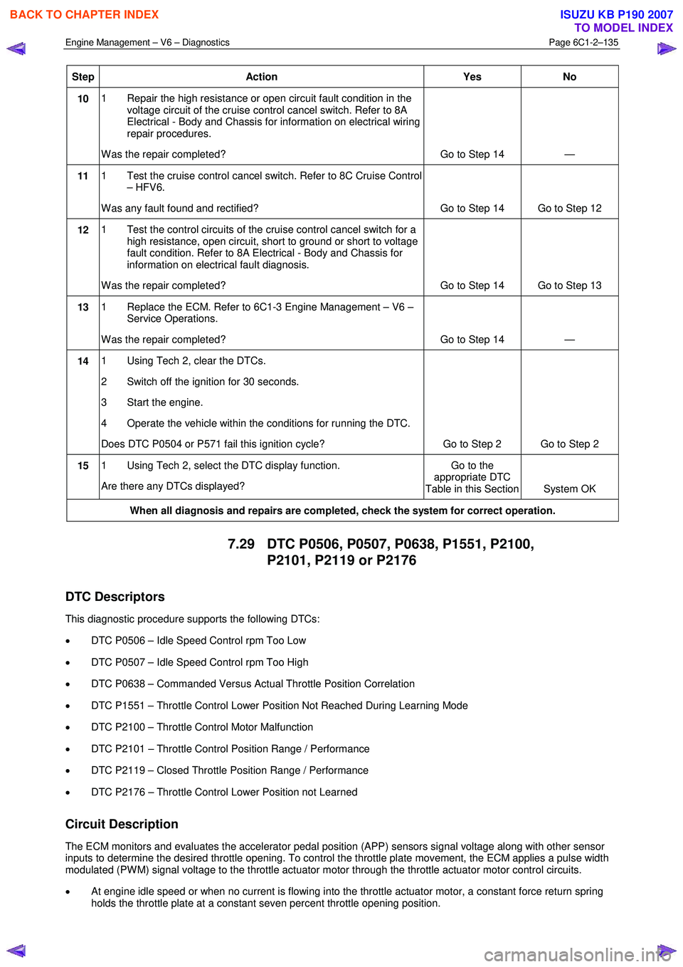
Step Action Yes No
10 1 Repair the high resistance or open circuit fault condition in the
voltage circuit of the cruise control cancel switch. Refer to 8A
Electrical - Body and Chassis for information on electrical wiring
repair procedures.
W as the repair completed? Go to Step 14 —
11 1 Test the cruise control cancel switch. Refer to 8C Cruise Control
– HFV6.
W as any fault found and rectified? Go to Step 14 Go to Step 12
12 1 Test the control circuits of the cruise control cancel switch for a
high resistance, open circuit, short to ground or short to voltage
fault condition. Refer to 8A Electrical - Body and Chassis for
information on electrical fault diagnosis.
W as the repair completed? Go to Step 14 Go to Step 13
13 1 Replace the ECM. Refer to 6C1-3 Engine Management – V6 –
Service Operations.
W as the repair completed? Go to Step 14 —
14 1 Using Tech 2, clear the DTCs.
2 Switch off the ignition for 30 seconds.
3 Start the engine.
4 Operate the vehicle within the conditions for running the DTC.
Does DTC P0504 or P571 fail this ignition cycle? Go to Step 2 Go to Step 2
15 1 Using Tech 2, select the DTC display function.
Are there any DTCs displayed? Go to the
appropriate DTC
Table in this Section System OK
When all diagnosis and repairs are completed, check the system for correct operation.
7.29 DTC P0506, P0507, P0638, P1551, P2100,
P2101, P2119 or P2176
DTC Descriptors
This diagnostic procedure supports the following DTCs:
• DTC P0506 – Idle Speed Control rpm Too Low
• DTC P0507 – Idle Speed Control rpm Too High
• DTC P0638 – Commanded Versus Actual Throttle Position Correlation
• DTC P1551 – Throttle Control Lower Position Not Reached During Learning Mode
• DTC P2100 – Throttle Control Motor Malfunction
• DTC P2101 – Throttle Control Position Range / Performance
• DTC P2119 – Closed Throttle Position Range / Performance
• DTC P2176 – Throttle Control Lower Position not Learned
Circuit Description
The ECM monitors and evaluates the accelerator pedal position (APP) sensors signal voltage along with other sensor
inputs to determine the desired throttle opening. To control the throttle plate movement, the ECM applies a pulse width
modulated (PW M) signal voltage to the throttle actuator motor through the throttle actuator motor control circuits.
• At engine idle speed or when no current is flowing into the throttle actuator motor, a constant force return spring
holds the throttle plate at a constant seven percent throttle opening position.
BACK TO CHAPTER INDEX
TO MODEL INDEX
ISUZU KB P190 2007
Page 3456 of 6020
Engine Management – V6 – Diagnostics Page 6C1-2–178
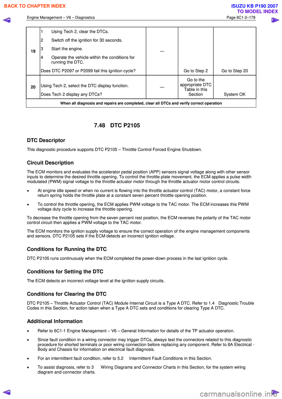
19 1 Using Tech 2, clear the DTCs.
2 Switch off the ignition for 30 seconds.
3 Start the engine.
4 Operate the vehicle within the conditions for running the DTC.
Does DTC P2097 or P2099 fail this ignition cycle? —
Go to Step 2 Go to Step 20
20 Using Tech 2, select the DTC display function.
Does Tech 2 display any DTCs? —
Go to the
appropriate DTC Table in this Section System OK
When all diagnosis and repairs are completed, clear all DTCs and verify correct operation
7.48 DTC P2105
DTC Descriptor
This diagnostic procedure supports DTC P2105 – Throttle Control Forced Engine Shutdown.
Circuit Description
The ECM monitors and evaluates the accelerator pedal position (APP) sensors signal voltage along with other sensor
inputs to determine the desired throttle opening. To control the throttle plate movement, the ECM applies a pulse width
modulated (PW M) signal voltage to the throttle actuator motor through the throttle actuator motor control circuits.
• At engine idle speed or when no current is flowing into the throttle actuator control (TAC) motor, a constant force
return spring holds the throttle plate at a constant seven percent throttle opening position.
• To control the throttle opening, the ECM applies PW M voltage to the TAC motor. The ECM increases this PW M
voltage duty cycle to increase the throttle opening.
To decrease the throttle opening from the seven percent rest position, the ECM reverses the polarity of the TAC motor
control circuit then applies a PW M voltage to the TAC motor.
The ECM monitors the ignition supply voltage to ensure the correct operation of the engine management components
and sensors. DTC P2105 sets if the ECM detects an incorrect ignition voltage.
Conditions for Running the DTC
DTC P2105 runs continuously when the ECM completed the power-down process in the last ignition cycle.
Conditions for Setting the DTC
The ECM detects an incorrect voltage level at the ignition supply circuits.
Conditions for Clearing the DTC
DTC P2105 – Throttle Actuator Control (TAC) Module Internal Circuit is a Type A DTC. Refer to 1.4 Diagnostic Trouble
Codes in this Section, for action taken when a Type A DTC sets and conditions for clearing Type A DTC.
Additional Information
• Refer to 6C1-1 Engine Management – V6 – General Information for details of the TP actuator operation.
• Since fault condition in a wiring connector may trigger DTCs, always test the connectors related to this diagnostic
procedure for shorted terminals or poor wiring connection before replacing any component. Refer to 8A Electrical -
Body and Chassis for information on electrical fault diagnosis.
• For an intermittent fault condition, refer to 5.2 Intermittent Fault Conditions in this Section.
• To assist diagnosis, refer to 3 W iring Diagrams and Connector Charts in this Section, for the system wiring
diagram and connector charts.
BACK TO CHAPTER INDEX
TO MODEL INDEX
ISUZU KB P190 2007
Page 3458 of 6020
Engine Management – V6 – Diagnostics Page 6C1-2–180
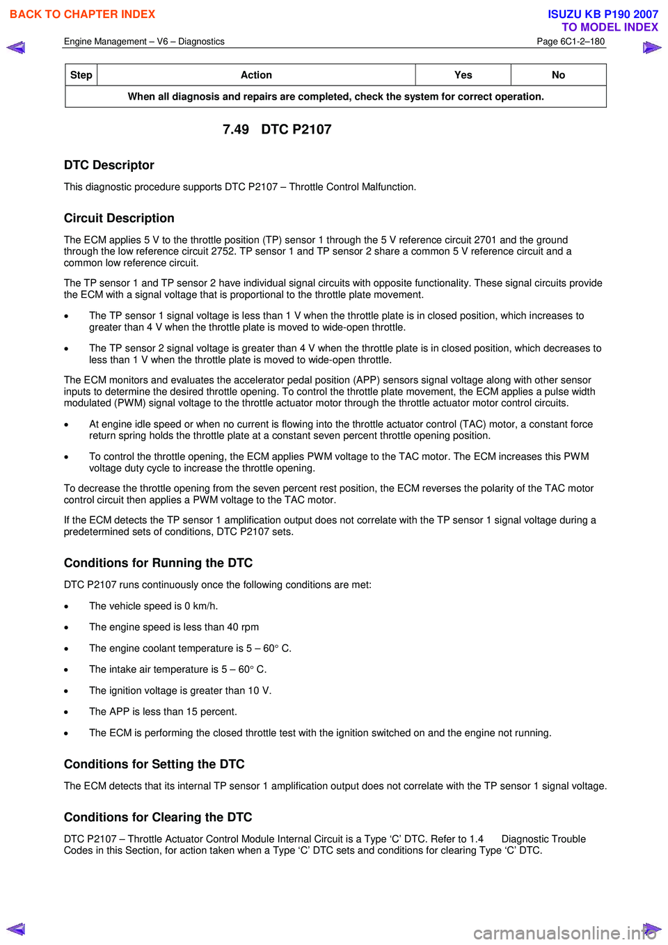
Step Action Yes
No
When all diagnosis and repairs are completed, check the system for correct operation.
7.49 DTC P2107
DTC Descriptor
This diagnostic procedure supports DTC P2107 – Throttle Control Malfunction.
Circuit Description
The ECM applies 5 V to the throttle position (TP) sensor 1 through the 5 V reference circuit 2701 and the ground
through the low reference circuit 2752. TP sensor 1 and TP sensor 2 share a common 5 V reference circuit and a
common low reference circuit.
The TP sensor 1 and TP sensor 2 have individual signal circuits with opposite functionality. These signal circuits provide
the ECM with a signal voltage that is proportional to the throttle plate movement.
• The TP sensor 1 signal voltage is less than 1 V when the throttle plate is in closed position, which increases to
greater than 4 V when the throttle plate is moved to wide-open throttle.
• The TP sensor 2 signal voltage is greater than 4 V when the throttle plate is in closed position, which decreases to
less than 1 V when the throttle plate is moved to wide-open throttle.
The ECM monitors and evaluates the accelerator pedal position (APP) sensors signal voltage along with other sensor
inputs to determine the desired throttle opening. To control the throttle plate movement, the ECM applies a pulse width
modulated (PW M) signal voltage to the throttle actuator motor through the throttle actuator motor control circuits.
• At engine idle speed or when no current is flowing into the throttle actuator control (TAC) motor, a constant force
return spring holds the throttle plate at a constant seven percent throttle opening position.
• To control the throttle opening, the ECM applies PW M voltage to the TAC motor. The ECM increases this PW M
voltage duty cycle to increase the throttle opening.
To decrease the throttle opening from the seven percent rest position, the ECM reverses the polarity of the TAC motor
control circuit then applies a PW M voltage to the TAC motor.
If the ECM detects the TP sensor 1 amplification output does not correlate with the TP sensor 1 signal voltage during a
predetermined sets of conditions, DTC P2107 sets.
Conditions for Running the DTC
DTC P2107 runs continuously once the following conditions are met:
• The vehicle speed is 0 km/h.
• The engine speed is less than 40 rpm
• The engine coolant temperature is 5 – 60 ° C.
• The intake air temperature is 5 – 60 ° C.
• The ignition voltage is greater than 10 V.
• The APP is less than 15 percent.
• The ECM is performing the closed throttle test with the ignition switched on and the engine not running.
Conditions for Setting the DTC
The ECM detects that its internal TP sensor 1 amplification output does not correlate with the TP sensor 1 signal voltage.
Conditions for Clearing the DTC
DTC P2107 – Throttle Actuator Control Module Internal Circuit is a Type ‘C’ DTC. Refer to 1.4 Diagnostic Trouble
Codes in this Section, for action taken when a Type ‘C’ DTC sets and conditions for clearing Type ‘C’ DTC.
BACK TO CHAPTER INDEX
TO MODEL INDEX
ISUZU KB P190 2007
Page 3486 of 6020
Engine Management – V6 – Diagnostics Page 6C1-2–208
Step Action Yes
No
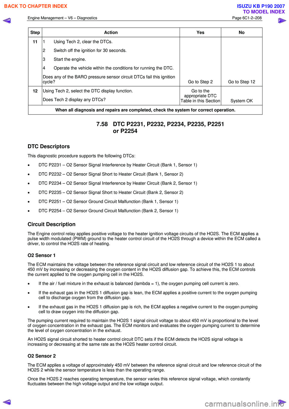
11 1 Using Tech 2, clear the DTCs.
2 Switch off the ignition for 30 seconds.
3 Start the engine.
4 Operate the vehicle within the conditions for running the DTC.
Does any of the BARO pressure sensor circuit DTCs fail this ignition
cycle? Go to Step 2 Go to Step 12
12 Using Tech 2, select the DTC display function.
Does Tech 2 display any DTCs? Go to the
appropriate DTC
Table in this Section System OK
When all diagnosis and repairs are completed, check the system for correct operation.
7.58 DTC P2231, P2232, P2234, P2235, P2251
or P2254
DTC Descriptors
This diagnostic procedure supports the following DTCs:
• DTC P2231 – O2 Sensor Signal Interference by Heater Circuit (Bank 1, Sensor 1)
• DTC P2232 – O2 Sensor Signal Short to Heater Circuit (Bank 1, Sensor 2)
• DTC P2234 – O2 Sensor Signal Interference by Heater Circuit (Bank 2, Sensor 1)
• DTC P2235 – O2 Sensor Signal Short to Heater Circuit (Bank 2, Sensor 2)
• DTC P2251 – O2 Sensor Ground Circuit Malfunction (Bank 1, Sensor 1)
• DTC P2254 – O2 Sensor Ground Circuit Malfunction (Bank 2, Sensor 1)
Circuit Description
The Engine control relay applies positive voltage to the heater ignition voltage circuits of the HO2S. The ECM applies a
pulse width modulated (PW M) ground to the heater control circuit of the HO2S through a device within the ECM called a
driver, to control the HO2S rate of heating.
O2 Sensor 1
The ECM maintains the voltage between the reference signal circuit and low reference circuit of the HO2S 1 to about
450 mV by increasing or decreasing the oxygen content in the HO2S diffusion gap. To achieve this, the ECM controls
the current applied to the oxygen pumping cell in the HO2S.
• If the air / fuel mixture in the exhaust is balanced (lambda = 1), the oxygen pumping cell current is zero.
• If the exhaust gas in the HO2S 1 diffusion gap is lean, the ECM applies a positive current to the oxygen pumping
cell to discharge oxygen from the diffusion gap.
• If the exhaust gas in the HO2S 1 diffusion gap is rich, the ECM applies a negative current to the oxygen pumping
cell to draw oxygen into the diffusion gap.
The pumping current required to maintain the HO2S 1 signal circuit voltage to about 450 mV is proportional to the level
of oxygen concentration in the exhaust gas. The ECM monitors and evaluates the oxygen pumping current to determine
the level of oxygen concentration in the exhaust.
An HO2S signal circuit shorted to heater control circuit DTC sets if the ECM detects the HO2S signal voltage is
increasing or decreasing at the same rate as the HO2S heater control circuit.
O2 Sensor 2
The ECM applies a voltage of approximately 450 mV between the reference signal circuit and low reference circuit of the
HO2S 2 while the sensor temperature is less than the operating range.
Once the HO2S 2 reaches operating temperature, the sensor varies this reference signal voltage, which constantly
fluctuates between the high voltage output and the low voltage output.
BACK TO CHAPTER INDEX
TO MODEL INDEX
ISUZU KB P190 2007
Page 3489 of 6020
Engine Management – V6 – Diagnostics Page 6C1-2–211
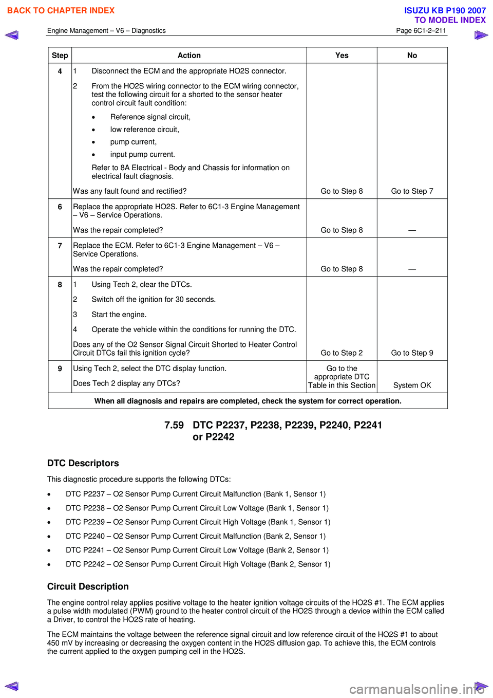
Step Action Yes No
4 1 Disconnect the ECM and the appropriate HO2S connector.
2 From the HO2S wiring connector to the ECM wiring connector, test the following circuit for a shorted to the sensor heater
control circuit fault condition:
• Reference signal circuit,
• low reference circuit,
• pump current,
• input pump current.
Refer to 8A Electrical - Body and Chassis for information on electrical fault diagnosis.
W as any fault found and rectified? Go to Step 8 Go to Step 7
6 Replace the appropriate HO2S. Refer to 6C1-3 Engine Management
– V6 – Service Operations.
W as the repair completed? Go to Step 8 —
7 Replace the ECM. Refer to 6C1-3 Engine Management – V6 –
Service Operations.
W as the repair completed? Go to Step 8 —
8 1 Using Tech 2, clear the DTCs.
2 Switch off the ignition for 30 seconds.
3 Start the engine.
4 Operate the vehicle within the conditions for running the DTC.
Does any of the O2 Sensor Signal Circuit Shorted to Heater Control
Circuit DTCs fail this ignition cycle? Go to Step 2 Go to Step 9
9 Using Tech 2, select the DTC display function.
Does Tech 2 display any DTCs? Go to the
appropriate DTC
Table in this Section System OK
When all diagnosis and repairs are completed, check the system for correct operation.
7.59 DTC P2237, P2238, P2239, P2240, P2241
or P2242
DTC Descriptors
This diagnostic procedure supports the following DTCs:
• DTC P2237 – O2 Sensor Pump Current Circuit Malfunction (Bank 1, Sensor 1)
• DTC P2238 – O2 Sensor Pump Current Circuit Low Voltage (Bank 1, Sensor 1)
• DTC P2239 – O2 Sensor Pump Current Circuit High Voltage (Bank 1, Sensor 1)
• DTC P2240 – O2 Sensor Pump Current Circuit Malfunction (Bank 2, Sensor 1)
• DTC P2241 – O2 Sensor Pump Current Circuit Low Voltage (Bank 2, Sensor 1)
• DTC P2242 – O2 Sensor Pump Current Circuit High Voltage (Bank 2, Sensor 1)
Circuit Description
The engine control relay applies positive voltage to the heater ignition voltage circuits of the HO2S #1. The ECM applies
a pulse width modulated (PW M) ground to the heater control circuit of the HO2S through a device within the ECM called
a Driver, to control the HO2S rate of heating.
The ECM maintains the voltage between the reference signal circuit and low reference circuit of the HO2S #1 to about
450 mV by increasing or decreasing the oxygen content in the HO2S diffusion gap. To achieve this, the ECM controls
the current applied to the oxygen pumping cell in the HO2S.
BACK TO CHAPTER INDEX
TO MODEL INDEX
ISUZU KB P190 2007
Page 3516 of 6020
Engine Management – V6 – Diagnostics Page 6C1-2–238
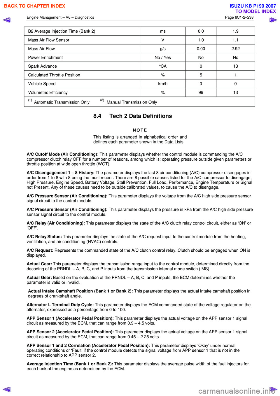
B2 Average Injection Time (Bank 2) ms 0.0 1.9
Mass Air Flow Sensor V 1.0 1.1
Mass Air Flow g/s 0.00 2.92
Power Enrichment No / Yes No No
Spark Advance °CA 0 13
Calculated Throttle Position % 5 1
Vehicle Speed km/h 0 0
Volumetric Efficiency % 99 13
(1) Automatic Transmission Only (2) Manual Transmission Only
8.4 Tech 2 Data Definitions
NOTE
This listing is arranged in alphabetical order and
defines each parameter shown in the Data Lists.
A/C Cutoff Mode (Air Conditioning): This parameter displays whether the control module is commanding the A/C
compressor clutch relay OFF for a number of reasons, among which is; operating pressure outside given parameters or
throttle position at wide open throttle (W OT).
A/C Disengagement 1 – 8 History: The parameter displays the last 8 air conditioning (A/C) compressor disengages in
order from 1 to 8 with 8 being the most recent. There are 8 possible causes listed for the A/C compressor to disengage;
High Pressure, Engine Speed, Battery Voltage, Stall Prevention, Full Load, Performance, Engine Temperature or Signal
not Present. Any of these causes need to be outside calibrated values, to cause the A/C to disengage.
A/C Pressure Sensor (Air Conditioning): This parameter displays the voltage from the A/C high side pressure sensor
signal circuit to the control module.
A/C Pressure Sensor (Air Conditioning): This parameter displays the pressure in kPa from the A/C high side pressure
sensor signal circuit to the control module.
A/C Relay (Air Conditioning): This parameter displays the state of the A/C clutch relay control circuit, either as ‘ON’ or
‘OFF’.
A/C Relay Status: This parameter displays the state of the A/C request input to the control module from the heating,
ventilation, and air conditioning (HVAC) controls.
A/C Request: Represents the commanded state of the A/C clutch control relay. Clutch should be engaged when ON is
displayed.
Actual Gear: This parameter displays the transmission range input to the control module, determined directly from the
decoding of the PRNDL – A, B, C, and P inputs from the transmission internal mode switch (IMS).
Actual Gear: Based on the evaluation of the PRNDL – A, B, C, and P inputs, the ECM determines whether the
parameter is valid or invalid.
Actual Intake Camshaft Position (Bank 1 or Bank 2): This parameter displays the actual intake camshaft position in
degrees of crankshaft angle.
Alternator L Terminal Duty Cycle: This parameter displays the ECM commanded state of the voltage regulator on the
alternator, expressed as a percentage from 0 to 100.
APP Sensor 1 (Accelerator Pedal Position): This parameter displays the actual voltage on the APP sensor 1 signal
circuit as measured by the ECM, that can range from 0.9 – 4.5 volts.
APP Sensor 2 (Accelerator Pedal Position): This parameter displays the actual voltage on the APP sensor 1 signal
circuit as measured by the ECM, that can range from 0.45 – 2.25 volts.
APP Sensor 1 and 2 Correlation (Accelerator Pedal Position): This parameter displays ‘Okay’ under normal
operating conditions or ‘Fault’ if the control module detects the signal voltage from APP sensor 1 that is not in the
correct relationship to APP sensor 2.
Average Injection Time (Bank 1 or Bank 2): This parameter displays the average pulse width of the fuel injectors for
each bank of the engine as determined by the ECM.
BACK TO CHAPTER INDEX
TO MODEL INDEX
ISUZU KB P190 2007
Page 3519 of 6020
Engine Management – V6 – Diagnostics Page 6C1-2–241
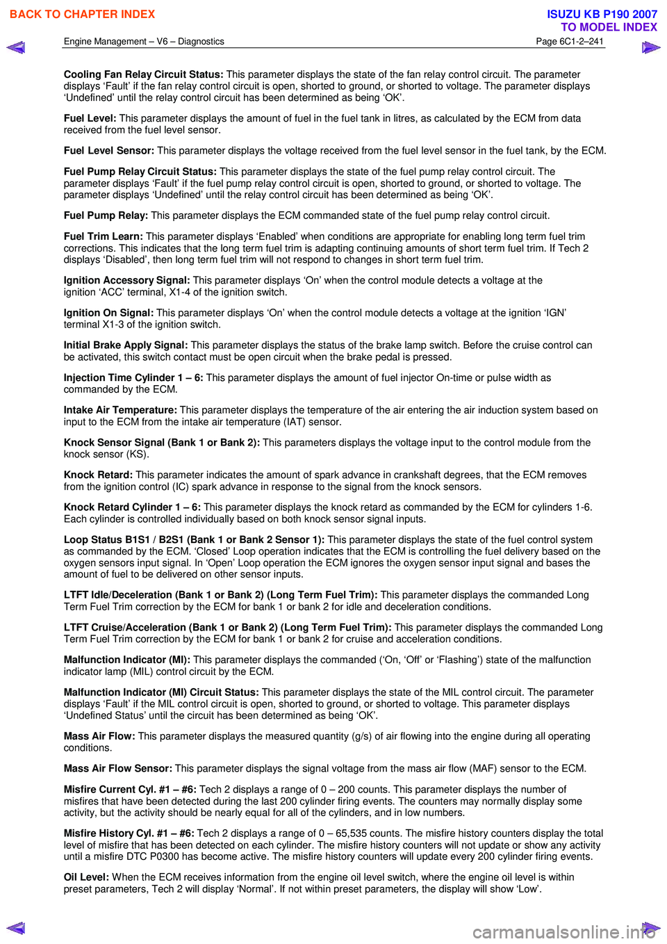
Cooling Fan Relay Circuit Status: This parameter displays the state of the fan relay control circuit. The parameter
displays ‘Fault’ if the fan relay control circuit is open, shorted to ground, or shorted to voltage. The parameter displays
‘Undefined’ until the relay control circuit has been determined as being ‘OK’.
Fuel Level: This parameter displays the amount of fuel in the fuel tank in litres, as calculated by the ECM from data
received from the fuel level sensor.
Fuel Level Sensor: This parameter displays the voltage received from the fuel level sensor in the fuel tank, by the ECM.
Fuel Pump Relay Circuit Status: This parameter displays the state of the fuel pump relay control circuit. The
parameter displays ‘Fault’ if the fuel pump relay control circuit is open, shorted to ground, or shorted to voltage. The
parameter displays ‘Undefined’ until the relay control circuit has been determined as being ‘OK’.
Fuel Pump Relay: This parameter displays the ECM commanded state of the fuel pump relay control circuit.
Fuel Trim Learn: This parameter displays ‘Enabled’ when conditions are appropriate for enabling long term fuel trim
corrections. This indicates that the long term fuel trim is adapting continuing amounts of short term fuel trim. If Tech 2
displays ‘Disabled’, then long term fuel trim will not respond to changes in short term fuel trim.
Ignition Accessory Signal: This parameter displays ‘On’ when the control module detects a voltage at the
ignition ‘ACC’ terminal, X1-4 of the ignition switch.
Ignition On Signal: This parameter displays ‘On’ when the control module detects a voltage at the ignition ‘IGN’
terminal X1-3 of the ignition switch.
Initial Brake Apply Signal: This parameter displays the status of the brake lamp switch. Before the cruise control can
be activated, this switch contact must be open circuit when the brake pedal is pressed.
Injection Time Cylinder 1 – 6: This parameter displays the amount of fuel injector On-time or pulse width as
commanded by the ECM.
Intake Air Temperature: This parameter displays the temperature of the air entering the air induction system based on
input to the ECM from the intake air temperature (IAT) sensor.
Knock Sensor Signal (Bank 1 or Bank 2): This parameters displays the voltage input to the control module from the
knock sensor (KS).
Knock Retard: This parameter indicates the amount of spark advance in crankshaft degrees, that the ECM removes
from the ignition control (IC) spark advance in response to the signal from the knock sensors.
Knock Retard Cylinder 1 – 6: This parameter displays the knock retard as commanded by the ECM for cylinders 1-6.
Each cylinder is controlled individually based on both knock sensor signal inputs.
Loop Status B1S1 / B2S1 (Bank 1 or Bank 2 Sensor 1): This parameter displays the state of the fuel control system
as commanded by the ECM. ‘Closed’ Loop operation indicates that the ECM is controlling the fuel delivery based on the
oxygen sensors input signal. In ‘Open’ Loop operation the ECM ignores the oxygen sensor input signal and bases the
amount of fuel to be delivered on other sensor inputs.
LTFT Idle/Deceleration (Bank 1 or Bank 2) (Long Term Fuel Trim): This parameter displays the commanded Long
Term Fuel Trim correction by the ECM for bank 1 or bank 2 for idle and deceleration conditions.
LTFT Cruise/Acceleration (Bank 1 or Bank 2) (Long Term Fuel Trim): This parameter displays the commanded Long
Term Fuel Trim correction by the ECM for bank 1 or bank 2 for cruise and acceleration conditions.
Malfunction Indicator (MI): This parameter displays the commanded (‘On, ‘Off’ or ‘Flashing’) state of the malfunction
indicator lamp (MIL) control circuit by the ECM.
Malfunction Indicator (MI) Circuit Status: This parameter displays the state of the MIL control circuit. The parameter
displays ‘Fault’ if the MIL control circuit is open, shorted to ground, or shorted to voltage. This parameter displays
‘Undefined Status’ until the circuit has been determined as being ‘OK’.
Mass Air Flow: This parameter displays the measured quantity (g/s) of air flowing into the engine during all operating
conditions.
Mass Air Flow Sensor: This parameter displays the signal voltage from the mass air flow (MAF) sensor to the ECM.
Misfire Current Cyl. #1 – #6: Tech 2 displays a range of 0 – 200 counts. This parameter displays the number of
misfires that have been detected during the last 200 cylinder firing events. The counters may normally display some
activity, but the activity should be nearly equal for all of the cylinders, and in low numbers.
Misfire History Cyl. #1 – #6: Tech 2 displays a range of 0 – 65,535 counts. The misfire history counters display the total
level of misfire that has been detected on each cylinder. The misfire history counters will not update or show any activity
until a misfire DTC P0300 has become active. The misfire history counters will update every 200 cylinder firing events.
Oil Level: W hen the ECM receives information from the engine oil level switch, where the engine oil level is within
preset parameters, Tech 2 will display ‘Normal’. If not within preset parameters, the display will show ‘Low’.
BACK TO CHAPTER INDEX
TO MODEL INDEX
ISUZU KB P190 2007
Page 3773 of 6020
Automatic Transmission – 4L60E – General Information Page 7C1–13
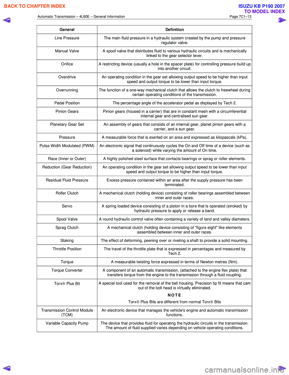
General Definition
Line Pressure The main fluid pressure in a hydraulic system created by the pump and pressure
regulator valve.
Manual Valve A spool valve that distributes fluid to various hydraulic circuits and is mechanically
linked to the gear selector lever.
Orifice A restricting device (usually a hole in the spacer plate) for controlling pressure build up
into another circuit.
Overdrive An operating condition in the gear set allowing output speed to be higher than input
speed and output torque to be lower than input torque.
Overrunning The function of a one-way mechanical clutch that allows the clutch to freewheel during certain operating conditions of the transmission.
Pedal Position The percentage angle of the accelerator pedal as displayed by Tech 2.
Pinion Gears Pinion gears (housed in a carrier) that are in constant mesh with a circumferential
internal gear and centralised sun gear.
Planetary Gear Set An assembly of gears that consists of an internal gear, planet pinion gears with a carrier, and a sun gear.
Pressure A measurable force that is exerted on an area and expressed as kilopascals (kPa).
Pulse Width Modulated (PW M) An electronic signal that continuously cycles the On and Off time of a device (such as
a solenoid) while varying the amount of On time.
Race (Inner or Outer) A highly polished steel surface that contacts bearings or sprag or roller elements.
Reduction (Gear Reduction) An operating condition in the gear set allowing output speed to be lower than input speed and output torque to be higher than input torque.
Residual Fluid Pressure Excess pressure contained within an area after the supply pressure has been terminated.
Roller Clutch A mechanical clutch (holding device) consisting of roller bearings assembled between inner and outer races.
Servo A spring loaded device consisting of a piston in a bore that is operated (stroked) by
hydraulic pressure to apply or release a band.
Spool Valve A round hydraulic control valve often containing a variety of land and valley diameters.
Sprag Clutch A mechanical clutch (holding device consisting of "figure eight" like elements
assembled between inner and outer races.
Staking The effect of deforming, peening over or riveting a shaft to provide a solid mounting.
Throttle Position The travel of the throttle plate that is expressed in percentages and measured by
Tech 2.
Torque A measurable twisting force expressed in terms of Newton metres (Nm).
Torque Converter A component of an automatic transmission, (attached to the engine flex plate) that
transfers torque from the engine to the transmission through a fluid coupling.
Torx Plus Bit A special tool used for the removal of the bell housing. Precision tip fit means that cam
out of the bolt head is virtually eliminated.
NOTE
Torx
Plus Bits are different from normal Torx
Bits
Transmission Control Module
(TCM) An electronic device that manages the vehicle's engine and automatic transmission
functions.
Variable Capacity Pump The device that provides fluid for operating the hydraulic circuits in the transmission. The amount of fluid supplied varies depending on vehicle operating conditions.
BACK TO CHAPTER INDEX
TO MODEL INDEX
ISUZU KB P190 2007