2007 ISUZU KB P190 width
[x] Cancel search: widthPage 3278 of 6020
Engine Management – V6 – General Information Page 6C1-1–36
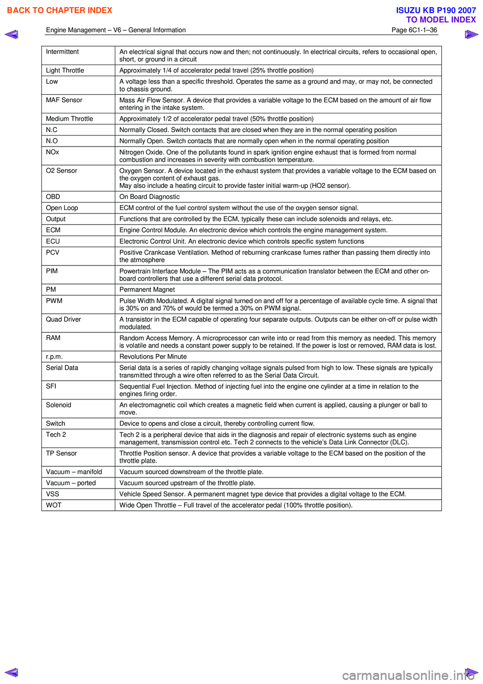
Intermittent
An electrical signal that occurs now and then; not continuously. In electrical circuits, refers to occasional open,
short, or ground in a circuit
Light Throttle Approximately 1/4 of accelerator pedal travel (25% throttle position)
Low
A voltage less than a specific threshold. Operates the same as a ground and may, or may not, be connected
to chassis ground.
MAF Sensor Mass Air Flow Sensor. A device that provides a variable voltage to the ECM based on the amount of air flow
entering in the intake system.
Medium Throttle Approximately 1/2 of accelerator pedal travel (50% throttle position)
N.C Normally Closed. Switch contacts that are closed when they are in the normal operating position
N.O Normally Open. Switch contacts that are normally open when in the normal operating position
NOx
Nitrogen Oxide. One of the pollutants found in spark ignition engine exhaust that is formed from normal
combustion and increases in severity with combustion temperature.
O2 Sensor Oxygen Sensor. A device located in the exhaust system that provides a variable voltage to the ECM based on
the oxygen content of exhaust gas.
May also include a heating circuit to provide faster initial warm-up (HO2 sensor).
OBD On Board Diagnostic
Open Loop ECM control of the fuel control system without the use of the oxygen sensor signal.
Output Functions that are controlled by the ECM, typically these can include solenoids and relays, etc.
ECM Engine Control Module. An electronic device which controls the engine management system.
ECU Electronic Control Unit. An electronic device which controls specific system functions
PCV
Positive Crankcase Ventilation. Method of reburning crankcase fumes rather than passing them directly into
the atmosphere
PIM Powertrain Interface Module – The PIM acts as a communication translator between the ECM and other on-
board controllers that use a different serial data protocol.
PM Permanent Magnet
PWM
Pulse Width Modulated. A digital signal turned on and off for a percentage of available cycle time. A signal that
is 30% on and 70% of would be termed a 30% on PWM signal.
Quad Driver A transistor in the ECM capable of operating four separate outputs. Outputs can be either on-off or pulse width
modulated.
RAM Random Access Memory. A microprocessor can write into or read from this memory as needed. This memory
is volatile and needs a constant power supply to be retained. If the power is lost or removed, RAM data is lost.
r.p.m. Revolutions Per Minute
Serial Data
Serial data is a series of rapidly changing voltage signals pulsed from high to low. These signals are typically
transmitted through a wire often referred to as the Serial Data Circuit.
SFI Sequential Fuel Injection. Method of injecting fuel into the engine one cylinder at a time in relation to the
engines firing order.
Solenoid An electromagnetic coil which creates a magnetic field when current is applied, causing a plunger or ball to
move.
Switch Device to opens and close a circuit, thereby controlling current flow.
Tech 2
Tech 2 is a peripheral device that aids in the diagnosis and repair of electronic systems such as engine
management, transmission control etc. Tech 2 connects to the vehicle’s Data Link Connector (DLC).
TP Sensor Throttle Position sensor. A device that provides a variable voltage to the ECM based on the position of the
throttle plate.
Vacuum – manifold Vacuum sourced downstream of the throttle plate.
Vacuum – ported Vacuum sourced upstream of the throttle plate.
VSS Vehicle Speed Sensor. A permanent magnet type device that provides a digital voltage to the ECM.
WOT Wide Open Throttle – Full travel of the accelerator pedal (100% throttle position).
BACK TO CHAPTER INDEX
TO MODEL INDEX
ISUZU KB P190 2007
Page 3338 of 6020
Engine Management – V6 – Diagnostics Page 6C1-2–60
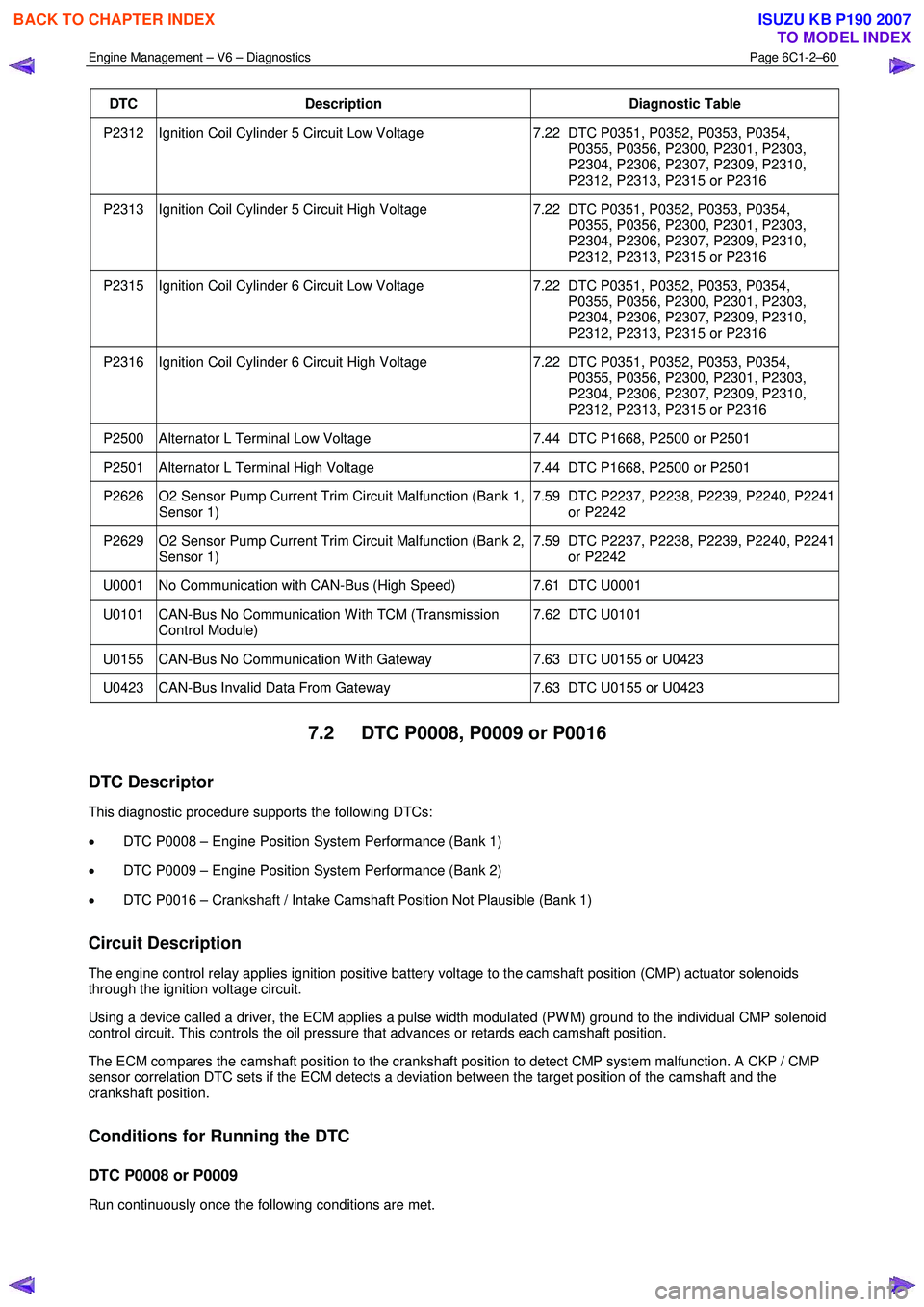
DTC Description Diagnostic Table
P2312 Ignition Coil Cylinder 5 Circuit Low Voltage 7.22 DTC P0351, P0352, P0353, P0354,
P0355, P0356, P2300, P2301, P2303,
P2304, P2306, P2307, P2309, P2310,
P2312, P2313, P2315 or P2316
P2313 Ignition Coil Cylinder 5 Circuit High Voltage 7.22 DTC P0351, P0352, P0353, P0354,
P0355, P0356, P2300, P2301, P2303,
P2304, P2306, P2307, P2309, P2310,
P2312, P2313, P2315 or P2316
P2315 Ignition Coil Cylinder 6 Circuit Low Voltage 7.22 DTC P0351, P0352, P0353, P0354,
P0355, P0356, P2300, P2301, P2303,
P2304, P2306, P2307, P2309, P2310,
P2312, P2313, P2315 or P2316
P2316 Ignition Coil Cylinder 6 Circuit High Voltage 7.22 DTC P0351, P0352, P0353, P0354,
P0355, P0356, P2300, P2301, P2303,
P2304, P2306, P2307, P2309, P2310,
P2312, P2313, P2315 or P2316
P2500 Alternator L Terminal Low Voltage 7.44 DTC P1668, P2500 or P2501
P2501 Alternator L Terminal High Voltage 7.44 DTC P1668, P2500 or P2501
P2626 O2 Sensor Pump Current Trim Circuit Malfunction (Bank 1,
Sensor 1) 7.59 DTC P2237, P2238, P2239, P2240, P2241
or P2242
P2629 O2 Sensor Pump Current Trim Circuit Malfunction (Bank 2, Sensor 1) 7.59 DTC P2237, P2238, P2239, P2240, P2241
or P2242
U0001 No Communication with CAN-Bus (High Speed) 7.61 DTC U0001
U0101 CAN-Bus No Communication W ith TCM (Transmission
Control Module) 7.62 DTC U0101
U0155 CAN-Bus No Communication W ith Gateway
7.63 DTC U0155 or U0423
U0423 CAN-Bus Invalid Data From Gateway 7.63 DTC U0155 or U0423
7.2 DTC P0008, P0009 or P0016
DTC Descriptor
This diagnostic procedure supports the following DTCs:
• DTC P0008 – Engine Position System Performance (Bank 1)
• DTC P0009 – Engine Position System Performance (Bank 2)
• DTC P0016 – Crankshaft / Intake Camshaft Position Not Plausible (Bank 1)
Circuit Description
The engine control relay applies ignition positive battery voltage to the camshaft position (CMP) actuator solenoids
through the ignition voltage circuit.
Using a device called a driver, the ECM applies a pulse width modulated (PW M) ground to the individual CMP solenoid
control circuit. This controls the oil pressure that advances or retards each camshaft position.
The ECM compares the camshaft position to the crankshaft position to detect CMP system malfunction. A CKP / CMP
sensor correlation DTC sets if the ECM detects a deviation between the target position of the camshaft and the
crankshaft position.
Conditions for Running the DTC
DTC P0008 or P0009
Run continuously once the following conditions are met.
BACK TO CHAPTER INDEX
TO MODEL INDEX
ISUZU KB P190 2007
Page 3341 of 6020
Engine Management – V6 – Diagnostics Page 6C1-2–63
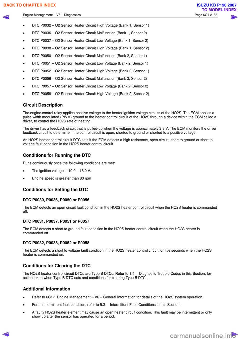
• DTC P0032 – O2 Sensor Heater Circuit High Voltage (Bank 1, Sensor 1)
• DTC P0036 – O2 Sensor Heater Circuit Malfunction (Bank 1, Sensor 2)
• DTC P0037 – O2 Sensor Heater Circuit Low Voltage (Bank 1, Sensor 2)
• DTC P0038 – O2 Sensor Heater Circuit High Voltage (Bank 1, Sensor 2)
• DTC P0050 – O2 Sensor Heater Circuit Malfunction (Bank 2, Sensor 1)
• DTC P0051 – O2 Sensor Heater Circuit Low Voltage (Bank 2, Sensor 1)
• DTC P0052 – O2 Sensor Heater Circuit High Voltage (Bank 2, Sensor 1)
• DTC P0056 – O2 Sensor Heater Circuit Malfunction (Bank 2, Sensor 2)
• DTC P0057 – O2 Sensor Heater Circuit Low Voltage (Bank 2, Sensor 2)
• DTC P0058 – O2 Sensor Heater Circuit High Voltage (Bank 2, Sensor 2)
Circuit Description
The engine control relay applies positive voltage to the heater ignition voltage circuits of the HO2S. The ECM applies a
pulse width modulated (PW M) ground to the heater control circuit of the HO2S through a device within the ECM called a
driver, to control the HO2S rate of heating.
The driver has a feedback circuit that is pulled-up when the voltage is approximately 3.3 V. The ECM monitors the driver
feedback circuit to determine if the control circuit is open, shorted to ground or shorted to a positive voltage.
An HO2S heater control circuit DTC sets if the ECM detects a high resistance, open circuit, short to ground or short to
voltage fault condition in the HO2S heater control circuit.
Conditions for Running the DTC
Runs continuously once the following conditions are met:
• The ignition voltage is 10.0 – 16.0 V.
• Engine speed is greater than 80 rpm
Conditions for Setting the DTC
DTC P0030, P0036, P0050 or P0056
The ECM detects an open circuit fault condition in the HO2S heater control circuit when the HO2S heater is commanded
off.
DTC P0031, P0037, P0051 or P0057
The ECM detects a short to ground fault condition in the HO2S heater control circuit when the HO2S heater is
commanded off.
DTC P0032, P0038, P0052 or P0058
The ECM detects a short to voltage fault condition in the HO2S heater control circuit for five seconds when the HO2S
heater is commanded on.
Conditions for Clearing the DTC
The HO2S heater control circuit DTCs are Type B DTCs. Refer to 1.4 Diagnostic Trouble Codes in this Section, for
action taken when Type B DTC sets and conditions for clearing Type B DTCs.
Additional Information
• Refer to 6C1-1 Engine Management – V6 – General Information for details of the HO2S system operation.
• For an intermittent fault condition, refer to 5.2 Intermittent Fault Conditions in this Section.
• A faulty HO2S heater element may cause an open heater circuit condition. This fault may be intermittent or only
show up after the sensor has operated for a period.
BACK TO CHAPTER INDEX
TO MODEL INDEX
ISUZU KB P190 2007
Page 3343 of 6020
Engine Management – V6 – Diagnostics Page 6C1-2–65
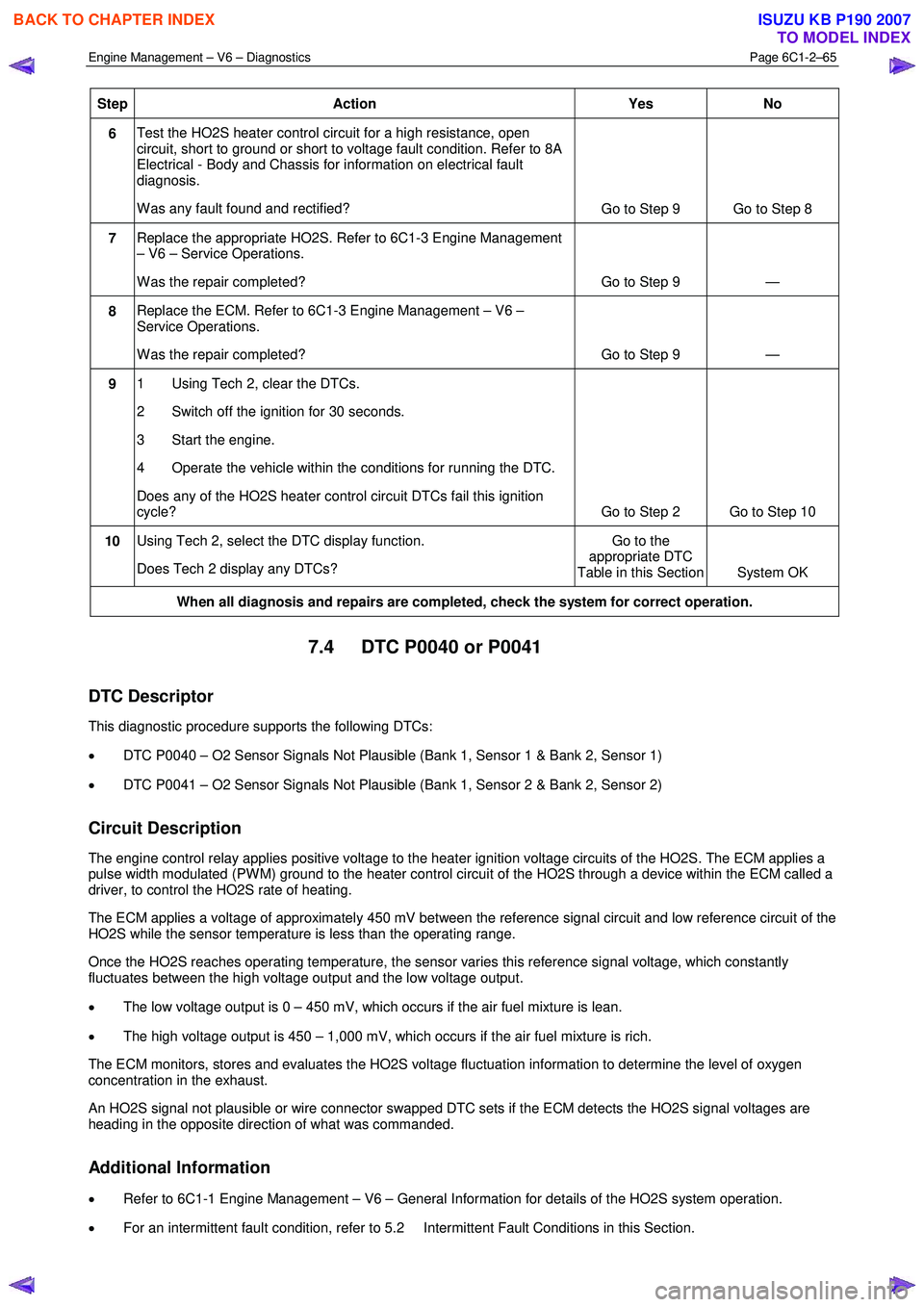
Step Action Yes No
6 Test the HO2S heater control circuit for a high resistance, open
circuit, short to ground or short to voltage fault condition. Refer to 8A
Electrical - Body and Chassis for information on electrical fault
diagnosis.
W as any fault found and rectified? Go to Step 9 Go to Step 8
7 Replace the appropriate HO2S. Refer to 6C1-3 Engine Management
– V6 – Service Operations.
W as the repair completed? Go to Step 9 —
8 Replace the ECM. Refer to 6C1-3 Engine Management – V6 –
Service Operations.
W as the repair completed? Go to Step 9 —
9 1 Using Tech 2, clear the DTCs.
2 Switch off the ignition for 30 seconds.
3 Start the engine.
4 Operate the vehicle within the conditions for running the DTC.
Does any of the HO2S heater control circuit DTCs fail this ignition
cycle? Go to Step 2 Go to Step 10
10 Using Tech 2, select the DTC display function.
Does Tech 2 display any DTCs? Go to the
appropriate DTC
Table in this Section System OK
When all diagnosis and repairs are completed, check the system for correct operation.
7.4 DTC P0040 or P0041
DTC Descriptor
This diagnostic procedure supports the following DTCs:
• DTC P0040 – O2 Sensor Signals Not Plausible (Bank 1, Sensor 1 & Bank 2, Sensor 1)
• DTC P0041 – O2 Sensor Signals Not Plausible (Bank 1, Sensor 2 & Bank 2, Sensor 2)
Circuit Description
The engine control relay applies positive voltage to the heater ignition voltage circuits of the HO2S. The ECM applies a
pulse width modulated (PW M) ground to the heater control circuit of the HO2S through a device within the ECM called a
driver, to control the HO2S rate of heating.
The ECM applies a voltage of approximately 450 mV between the reference signal circuit and low reference circuit of the
HO2S while the sensor temperature is less than the operating range.
Once the HO2S reaches operating temperature, the sensor varies this reference signal voltage, which constantly
fluctuates between the high voltage output and the low voltage output.
• The low voltage output is 0 – 450 mV, which occurs if the air fuel mixture is lean.
• The high voltage output is 450 – 1,000 mV, which occurs if the air fuel mixture is rich.
The ECM monitors, stores and evaluates the HO2S voltage fluctuation information to determine the level of oxygen
concentration in the exhaust.
An HO2S signal not plausible or wire connector swapped DTC sets if the ECM detects the HO2S signal voltages are
heading in the opposite direction of what was commanded.
Additional Information
• Refer to 6C1-1 Engine Management – V6 – General Information for details of the HO2S system operation.
• For an intermittent fault condition, refer to 5.2 Intermittent Fault Conditions in this Section.
BACK TO CHAPTER INDEX
TO MODEL INDEX
ISUZU KB P190 2007
Page 3345 of 6020
Engine Management – V6 – Diagnostics Page 6C1-2–67
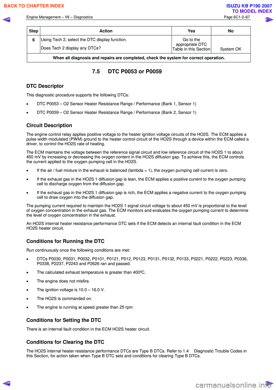
Step Action Yes No
6 Using Tech 2, select the DTC display function.
Does Tech 2 display any DTCs? Go to the
appropriate DTC
Table in this Section System OK
When all diagnosis and repairs are completed, check the system for correct operation.
7.5 DTC P0053 or P0059
DTC Descriptor
This diagnostic procedure supports the following DTCs:
• DTC P0053 – O2 Sensor Heater Resistance Range / Performance (Bank 1, Sensor 1)
• DTC P0059 – O2 Sensor Heater Resistance Range / Performance (Bank 2, Sensor 1)
Circuit Description
The engine control relay applies positive voltage to the heater ignition voltage circuits of the HO2S. The ECM applies a
pulse width modulated (PW M) ground to the heater control circuit of the HO2S through a device within the ECM called a
driver, to control the HO2S rate of heating.
The ECM maintains the voltage between the reference signal circuit and low reference circuit of the HO2S 1 to about
450 mV by increasing or decreasing the oxygen content in the HO2S diffusion gap. To achieve this, the ECM controls
the current applied to the oxygen pumping cell in the HO2S.
• If the air / fuel mixture in the exhaust is balanced (lambda = 1), the oxygen pumping cell current is zero.
• If the exhaust gas in the HO2S 1 diffusion gap is lean, the ECM applies a positive current to the oxygen pumping
cell to discharge oxygen from the diffusion gap.
• If the exhaust gas in the HO2S 1 diffusion gap is rich, the ECM applies a negative current to the oxygen pumping
cell to draw oxygen into the diffusion gap.
The pumping current required to maintain the HO2S 1 signal circuit voltage to about 450 mV is proportional to the level
of oxygen concentration in the exhaust gas. The ECM monitors and evaluates the oxygen pumping current to determine
the level of oxygen concentration in the exhaust.
An HO2S internal heater resistance performance DTC sets if the ECM detects an internal fault condition in the ECM
HO2S heater circuit.
Conditions for Running the DTC
Run continuously once the following conditions are met:
• DTCs P0030, P0031, P0032, P0101, P0121, P012, P0123, P0131, P0132, P0133, P0221, P0222, P0223, P0336,
P0338, P2237, P2243 and P2626 ran and passed.
• The calculated exhaust temperature is greater than 400ºC.
• The engine does not misfire.
• The ignition voltage is 10.0 – 16.0 V.
• The HO2S is commanded on.
• The engine is running at speed greater than 25 rpm
Conditions for Setting the DTC
There is an internal fault condition in the ECM HO2S heater circuit.
Conditions for Clearing the DTC
The HO2S internal heater resistance performance DTCs are Type B DTCs. Refer to 1.4 Diagnostic Trouble Codes in
this Section, for action taken when Type B DTC sets and conditions for clearing Type B DTCs.
BACK TO CHAPTER INDEX
TO MODEL INDEX
ISUZU KB P190 2007
Page 3360 of 6020
Engine Management – V6 – Diagnostics Page 6C1-2–82
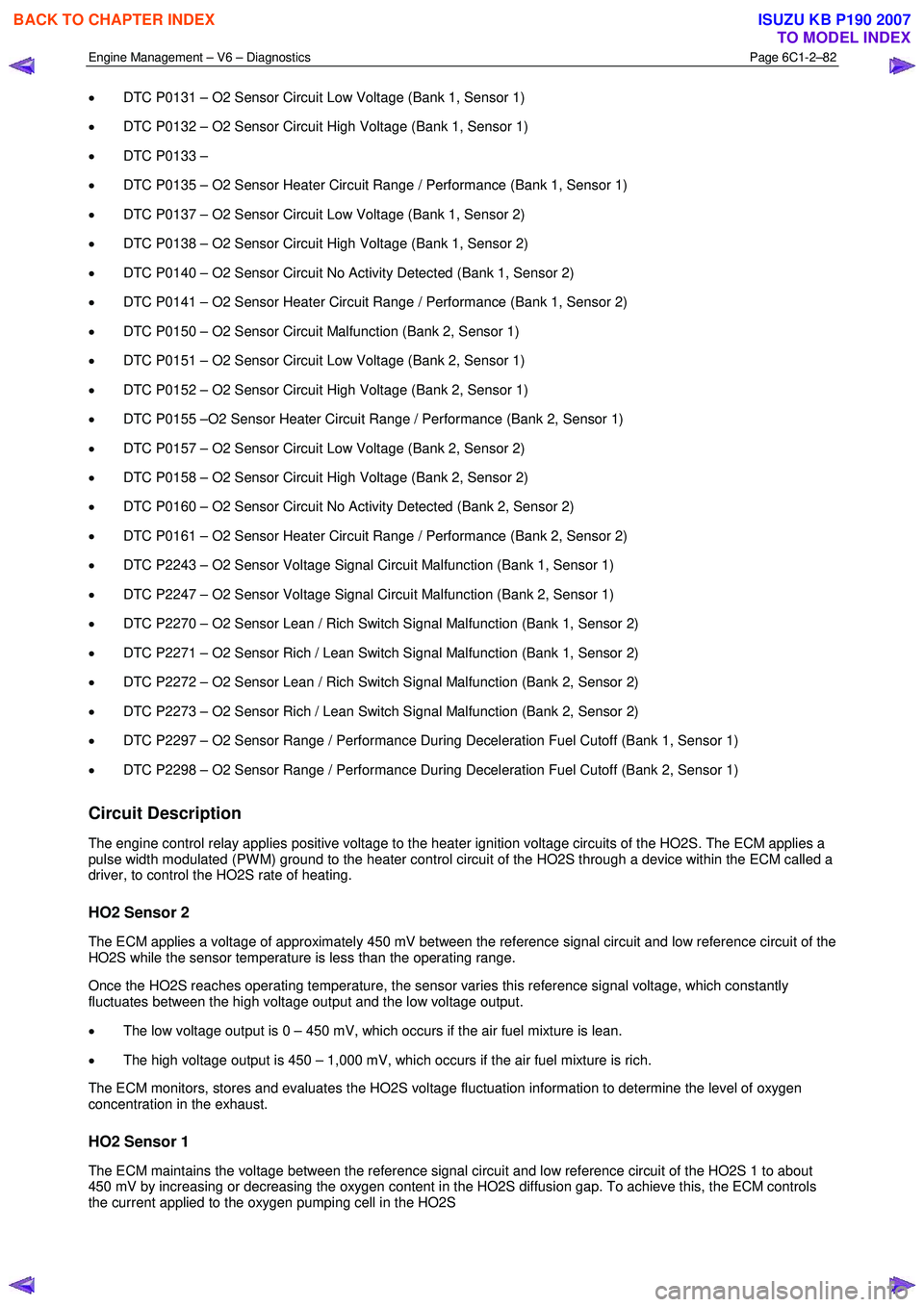
• DTC P0131 – O2 Sensor Circuit Low Voltage (Bank 1, Sensor 1)
• DTC P0132 – O2 Sensor Circuit High Voltage (Bank 1, Sensor 1)
• DTC P0133 –
• DTC P0135 – O2 Sensor Heater Circuit Range / Performance (Bank 1, Sensor 1)
• DTC P0137 – O2 Sensor Circuit Low Voltage (Bank 1, Sensor 2)
• DTC P0138 – O2 Sensor Circuit High Voltage (Bank 1, Sensor 2)
• DTC P0140 – O2 Sensor Circuit No Activity Detected (Bank 1, Sensor 2)
• DTC P0141 – O2 Sensor Heater Circuit Range / Performance (Bank 1, Sensor 2)
• DTC P0150 – O2 Sensor Circuit Malfunction (Bank 2, Sensor 1)
• DTC P0151 – O2 Sensor Circuit Low Voltage (Bank 2, Sensor 1)
• DTC P0152 – O2 Sensor Circuit High Voltage (Bank 2, Sensor 1)
• DTC P0155 –O2 Sensor Heater Circuit Range / Performance (Bank 2, Sensor 1)
• DTC P0157 – O2 Sensor Circuit Low Voltage (Bank 2, Sensor 2)
• DTC P0158 – O2 Sensor Circuit High Voltage (Bank 2, Sensor 2)
• DTC P0160 – O2 Sensor Circuit No Activity Detected (Bank 2, Sensor 2)
• DTC P0161 – O2 Sensor Heater Circuit Range / Performance (Bank 2, Sensor 2)
• DTC P2243 – O2 Sensor Voltage Signal Circuit Malfunction (Bank 1, Sensor 1)
• DTC P2247 – O2 Sensor Voltage Signal Circuit Malfunction (Bank 2, Sensor 1)
• DTC P2270 – O2 Sensor Lean / Rich Switch Signal Malfunction (Bank 1, Sensor 2)
• DTC P2271 – O2 Sensor Rich / Lean Switch Signal Malfunction (Bank 1, Sensor 2)
• DTC P2272 – O2 Sensor Lean / Rich Switch Signal Malfunction (Bank 2, Sensor 2)
• DTC P2273 – O2 Sensor Rich / Lean Switch Signal Malfunction (Bank 2, Sensor 2)
• DTC P2297 – O2 Sensor Range / Performance During Deceleration Fuel Cutoff (Bank 1, Sensor 1)
• DTC P2298 – O2 Sensor Range / Performance During Deceleration Fuel Cutoff (Bank 2, Sensor 1)
Circuit Description
The engine control relay applies positive voltage to the heater ignition voltage circuits of the HO2S. The ECM applies a
pulse width modulated (PW M) ground to the heater control circuit of the HO2S through a device within the ECM called a
driver, to control the HO2S rate of heating.
HO2 Sensor 2
The ECM applies a voltage of approximately 450 mV between the reference signal circuit and low reference circuit of the
HO2S while the sensor temperature is less than the operating range.
Once the HO2S reaches operating temperature, the sensor varies this reference signal voltage, which constantly
fluctuates between the high voltage output and the low voltage output.
• The low voltage output is 0 – 450 mV, which occurs if the air fuel mixture is lean.
• The high voltage output is 450 – 1,000 mV, which occurs if the air fuel mixture is rich.
The ECM monitors, stores and evaluates the HO2S voltage fluctuation information to determine the level of oxygen
concentration in the exhaust.
HO2 Sensor 1
The ECM maintains the voltage between the reference signal circuit and low reference circuit of the HO2S 1 to about
450 mV by increasing or decreasing the oxygen content in the HO2S diffusion gap. To achieve this, the ECM controls
the current applied to the oxygen pumping cell in the HO2S
BACK TO CHAPTER INDEX
TO MODEL INDEX
ISUZU KB P190 2007
Page 3376 of 6020
Engine Management – V6 – Diagnostics Page 6C1-2–98
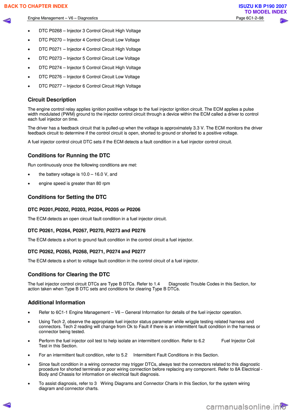
• DTC P0268 – Injector 3 Control Circuit High Voltage
• DTC P0270 – Injector 4 Control Circuit Low Voltage
• DTC P0271 – Injector 4 Control Circuit High Voltage
• DTC P0273 – Injector 5 Control Circuit Low Voltage
• DTC P0274 – Injector 5 Control Circuit High Voltage
• DTC P0276 – Injector 6 Control Circuit Low Voltage
• DTC P0277 – Injector 6 Control Circuit High Voltage
Circuit Description
The engine control relay applies ignition positive voltage to the fuel injector ignition circuit. The ECM applies a pulse
width modulated (PW M) ground to the injector control circuit through a device within the ECM called a driver to control
each fuel injector on time.
The driver has a feedback circuit that is pulled-up when the voltage is approximately 3.3 V. The ECM monitors the driver
feedback circuit to determine if the control circuit is open, shorted to ground or shorted to a positive voltage.
A fuel injector control circuit DTC sets if the ECM detects a fault condition in a fuel injector control circuit.
Conditions for Running the DTC
Run continuously once the following conditions are met:
• the battery voltage is 10.0 – 16.0 V, and
• engine speed is greater than 80 rpm
Conditions for Setting the DTC
DTC P0201,P0202, P0203, P0204, P0205 or P0206
The ECM detects an open circuit fault condition in a fuel injector circuit.
DTC P0261, P0264, P0267, P0270, P0273 and P0276
The ECM detects a short to ground fault condition in the control circuit a fuel injector.
DTC P0262, P0265, P0268, P0271, P0274 and P0277
The ECM detects a short to voltage fault condition in the control circuit of a fuel injector.
Conditions for Clearing the DTC
The fuel injector control circuit DTCs are Type B DTCs. Refer to 1.4 Diagnostic Trouble Codes in this Section, for
action taken when Type B DTC sets and conditions for clearing Type B DTCs.
Additional Information
• Refer to 6C1-1 Engine Management – V6 – General Information for details of the fuel injector operation.
• Using Tech 2, observe the appropriate fuel injector status parameter while wriggle testing related harness and
connectors. Tech 2 reading will change from Ok to Fault if there is an intermittent fault condition in the harness or
connector being tested.
• Perform the fuel injector coil test to help isolate an intermittent condition. Refer to 6.2 Fuel Injector Coil
Test in this Section.
• For an intermittent fault condition, refer to 5.2 Intermittent Fault Conditions in this Section.
• Since fault condition in a wiring connector may trigger DTCs, always test the connectors related to this diagnostic
procedure for shorted terminals or poor wiring connection before replacing any component. Refer to 8A Electrical -
Body and Chassis for information on electrical fault diagnosis.
• To assist diagnosis, refer to 3 W iring Diagrams and Connector Charts in this Section, for the system wiring
diagram and connector charts.
BACK TO CHAPTER INDEX
TO MODEL INDEX
ISUZU KB P190 2007
Page 3401 of 6020
Engine Management – V6 – Diagnostics Page 6C1-2–123
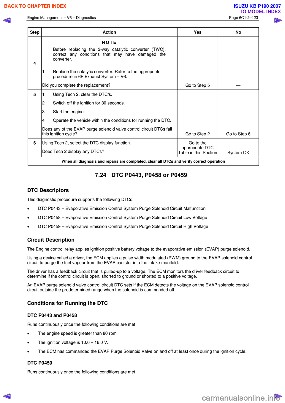
Step Action Yes No
4 NOTE
Before replacing the 3-way catalytic converter (TW C),
correct any conditions that may have damaged the
converter.
1 Replace the catalytic converter. Refer to the appropriate procedure in 6F Exhaust System – V6.
Did you complete the replacement? Go to Step 5 —
5 1 Using Tech 2, clear the DTC/s.
2 Switch off the ignition for 30 seconds.
3 Start the engine.
4 Operate the vehicle within the conditions for running the DTC.
Does any of the EVAP purge solenoid valve control circuit DTCs fail
this ignition cycle? Go to Step 2 Go to Step 6
6 Using Tech 2, select the DTC display function.
Does Tech 2 display any DTCs? Go to the
appropriate DTC
Table in this Section System OK
When all diagnosis and repairs are completed, clear all DTCs and verify correct operation
7.24 DTC P0443, P0458 or P0459
DTC Descriptors
This diagnostic procedure supports the following DTCs:
• DTC P0443 – Evaporative Emission Control System Purge Solenoid Circuit Malfunction
• DTC P0458 – Evaporative Emission Control System Purge Solenoid Circuit Low Voltage
• DTC P0459 – Evaporative Emission Control System Purge Solenoid Circuit High Voltage
Circuit Description
The Engine control relay applies ignition positive battery voltage to the evaporative emission (EVAP) purge solenoid.
Using a device called a driver, the ECM applies a pulse width modulated (PW M) ground to the EVAP solenoid control
circuit to purge the fuel vapour from the EVAP canister into the intake manifold.
The driver has a feedback circuit that is pulled-up to a voltage. The ECM monitors the driver feedback circuit to
determine if the control circuit is open, shorted to ground or shorted to a positive voltage.
An EVAP purge solenoid valve control circuit DTC sets if the ECM detects the voltage on the EVAP solenoid control
circuit outside the predetermined range when the solenoid is commanded off.
Conditions for Running the DTC
DTC P0443 and P0458
Runs continuously once the following conditions are met:
• The engine speed is greater than 80 rpm
• The ignition voltage is 10.0 – 16.0 V.
• The ECM has commanded the EVAP Purge Solenoid Valve on and off at least once during the ignition cycle.
DTC P0459
Runs continuously once the following conditions are met:
BACK TO CHAPTER INDEX
TO MODEL INDEX
ISUZU KB P190 2007