2007 ISUZU KB P190 width
[x] Cancel search: widthPage 2651 of 6020
Engine Mechanical – V6 Page 6A1–172
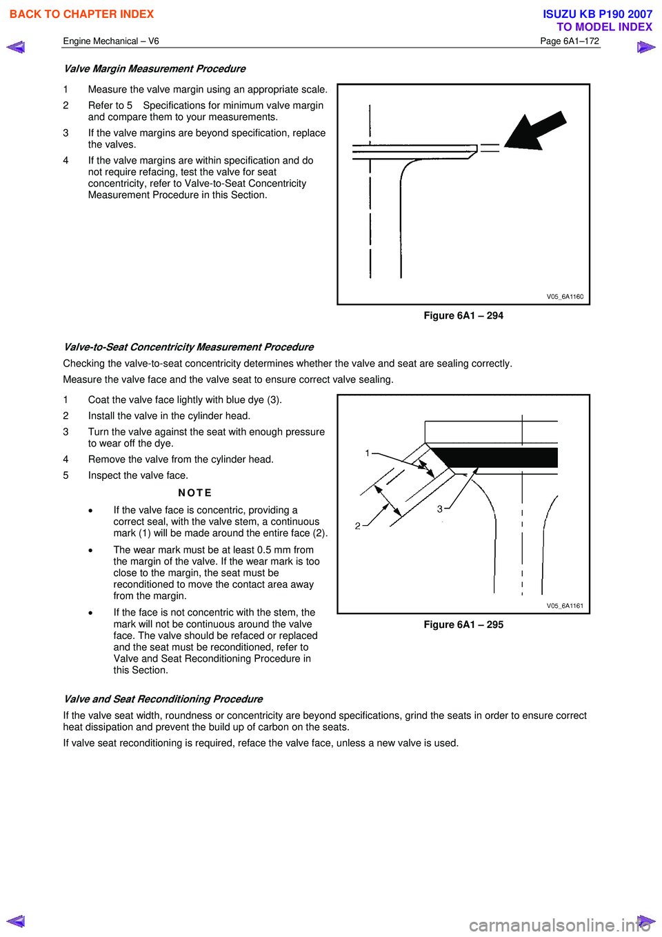
Valve Margin Measurement Procedure
1 Measure the valve margin using an appropriate scale.
2 Refer to 5 Specifications for minimum valve margin and compare them to your measurements.
3 If the valve margins are beyond specification, replace the valves.
4 If the valve margins are within specification and do not require refacing, test the valve for seat
concentricity, refer to Valve-to-Seat Concentricity
Measurement Procedure in this Section.
Figure 6A1 – 294
Valve-to-Seat Concentricity Measurement Procedure
Checking the valve-to-seat concentricity determines whether the valve and seat are sealing correctly.
Measure the valve face and the valve seat to ensure correct valve sealing.
1 Coat the valve face lightly with blue dye (3).
2 Install the valve in the cylinder head.
3 Turn the valve against the seat with enough pressure to wear off the dye.
4 Remove the valve from the cylinder head.
5 Inspect the valve face.
NOTE
• If the valve face is concentric, providing a
correct seal, with the valve stem, a continuous
mark (1) will be made around the entire face (2).
• The wear mark must be at least 0.5 mm from
the margin of the valve. If the wear mark is too
close to the margin, the seat must be
reconditioned to move the contact area away
from the margin.
• If the face is not concentric with the stem, the
mark will not be continuous around the valve
face. The valve should be refaced or replaced
and the seat must be reconditioned, refer to
Valve and Seat Reconditioning Procedure in
this Section.
Figure 6A1 – 295
Valve and Seat Reconditioning Procedure
If the valve seat width, roundness or concentricity are beyond specifications, grind the seats in order to ensure correct
heat dissipation and prevent the build up of carbon on the seats.
If valve seat reconditioning is required, reface the valve face, unless a new valve is used.
BACK TO CHAPTER INDEX
TO MODEL INDEX
ISUZU KB P190 2007
Page 2652 of 6020
Engine Mechanical – V6 Page 6A1–173
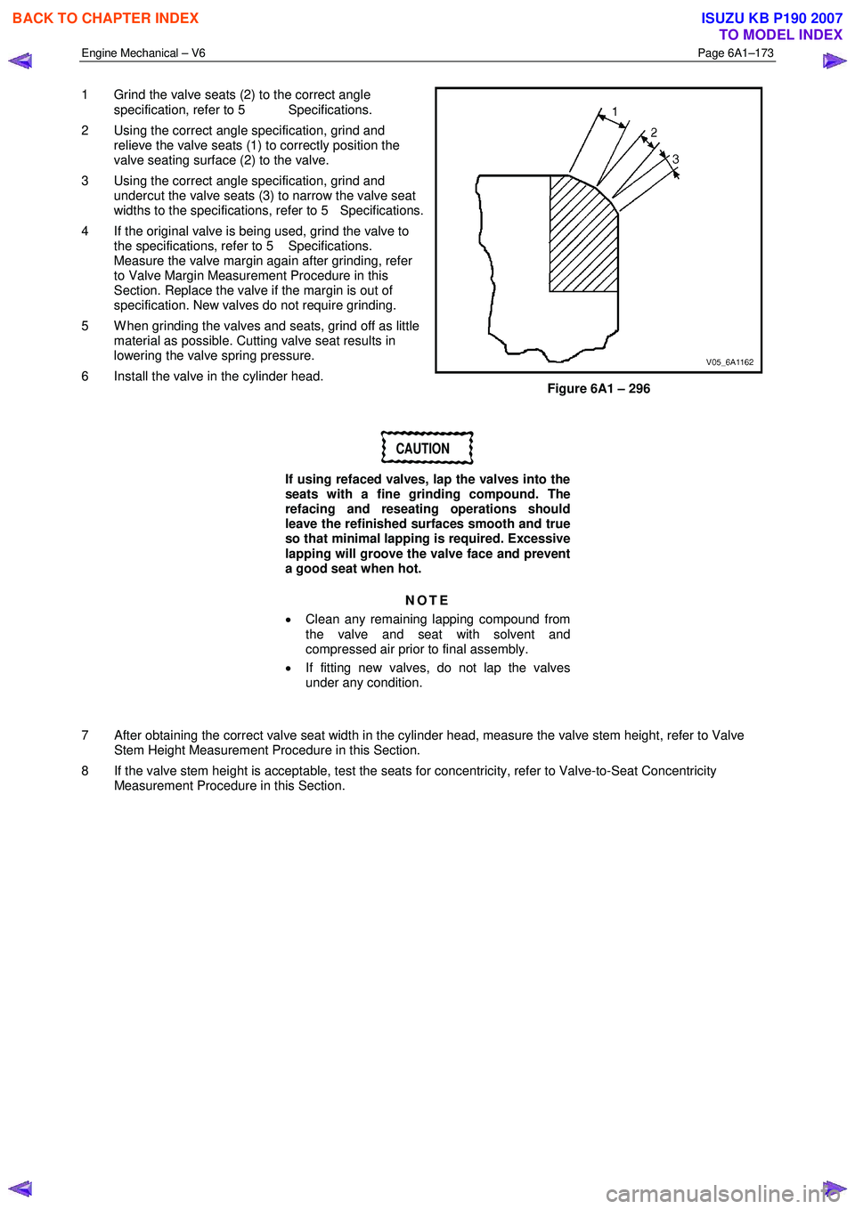
1 Grind the valve seats (2) to the correct angle
specification, refer to 5 Specifications.
2 Using the correct angle specification, grind and relieve the valve seats (1) to correctly position the
valve seating surface (2) to the valve.
3 Using the correct angle specification, grind and undercut the valve seats (3) to narrow the valve seat
widths to the specifications, refer to 5 Specifications.
4 If the original valve is being used, grind the valve to the specifications, refer to 5 Specifications.
Measure the valve margin again after grinding, refer
to Valve Margin Measurement Procedure in this
Section. Replace the valve if the margin is out of
specification. New valves do not require grinding.
5 W hen grinding the valves and seats, grind off as little material as possible. Cutting valve seat results in
lowering the valve spring pressure.
6 Install the valve in the cylinder head.
Figure 6A1 – 296
CAUTION
If using refaced valves, lap the valves into the
seats with a fine grinding compound. The
refacing and reseating operations should
leave the refinished surfaces smooth and true
so that minimal lapping is required. Excessive
lapping will groove the valve face and prevent
a good seat when hot.
NOTE
• Clean any remaining lapping compound from
the valve and seat with solvent and
compressed air prior to final assembly.
• If fitting new valves, do not lap the valves
under any condition.
7 After obtaining the correct valve seat width in the cylinder head, measure the valve stem height, refer to Valve Stem Height Measurement Procedure in this Section.
8 If the valve stem height is acceptable, test the seats for concentricity, refer to Valve-to-Seat Concentricity Measurement Procedure in this Section.
BACK TO CHAPTER INDEX
TO MODEL INDEX
ISUZU KB P190 2007
Page 2688 of 6020
Engine Mechanical – V6 Page 6A1–209
d If the endplay exceeds the specified limits, measure the width of the crankpin end of the connecting rod, refer
to 5 Specifications.
e If the connecting rod width is significantly smaller than specified and severe wear is present on the side of the connecting rod, replace the connecting rod.
f If the connecting rod width is within specification and excessive scoring is present on the crankshaft journals, replace the crankshaft.
CAUTION
Do not use a stamp, punch or any other
method that may distort or stress the
connecting rod and cap. Extensive engine
damage may result from a connecting rod that
is distorted or stressed.
8 Mark the cylinder number on the connecting rod and the connecting rod cap with a paint stick or permanent marker.
CAUTION
Powdered metal connecting rods have rod
bolts which yield when tighten to the
specified torque. If the bolts are loosened or
removed they must be replaced. Rod bolts
that are not replaced will not torque to the
correct clamp load and can lead to serious
engine damage.
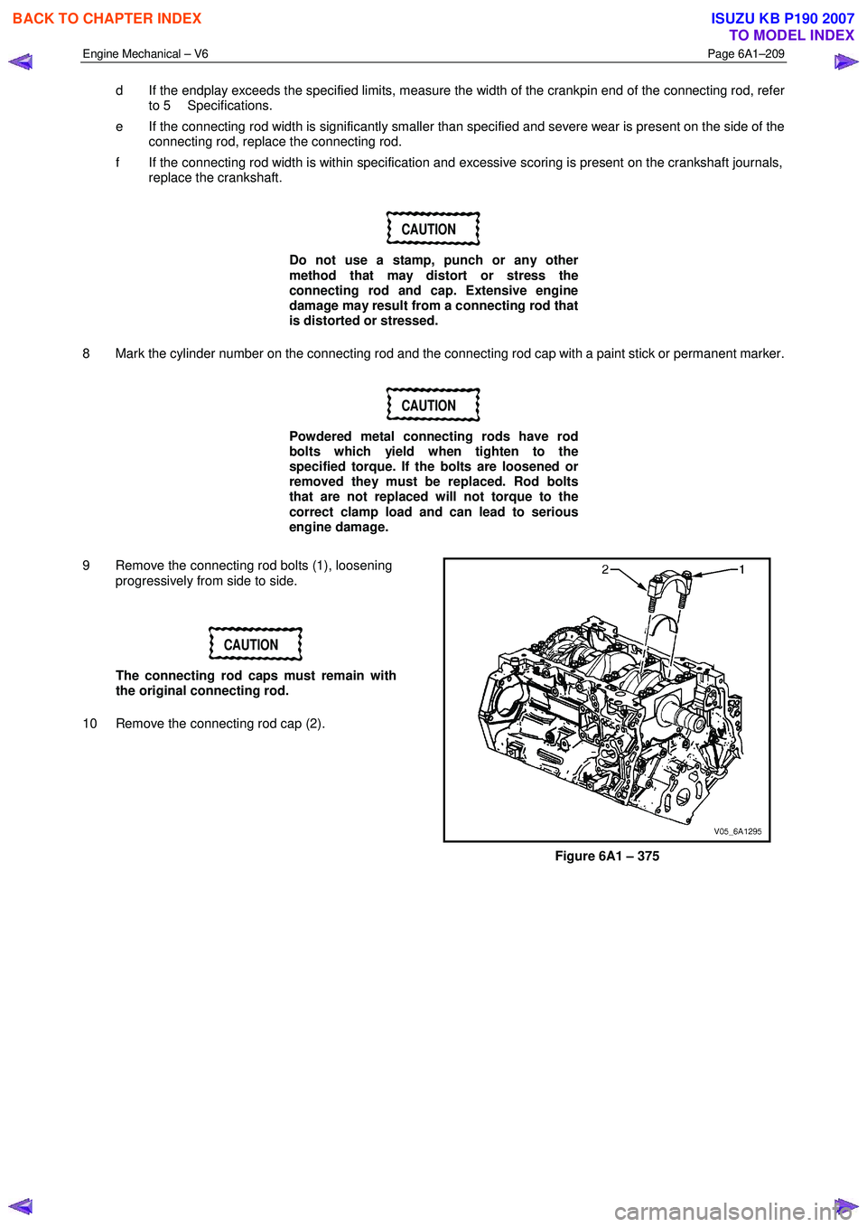
9 Remove the connecting rod bolts (1), loosening progressively from side to side.
CAUTION
The connecting rod caps must remain with
the original connecting rod.
10 Remove the connecting rod cap (2).
Figure 6A1 – 375
BACK TO CHAPTER INDEX
TO MODEL INDEX
ISUZU KB P190 2007
Page 2692 of 6020
Engine Mechanical – V6 Page 6A1–213
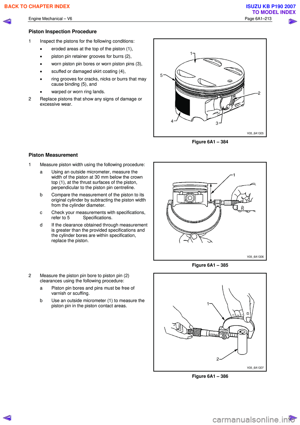
Piston Inspection Procedure
1 Inspect the pistons for the following conditions:
• eroded areas at the top of the piston (1),
• piston pin retainer grooves for burrs (2),
• worn piston pin bores or worn piston pins (3),
• scuffed or damaged skirt coating (4),
• ring grooves for cracks, nicks or burrs that may
cause binding (5), and
• warped or worn ring lands.
2 Replace pistons that show any signs of damage or excessive wear.
Figure 6A1 – 384
Piston Measurement
1 Measure piston width using the following procedure:
a Using an outside micrometer, measure the width of the piston at 30 mm below the crown
top (1), at the thrust surfaces of the piston,
perpendicular to the piston pin centreline.
b Compare the measurement of the piston to its original cylinder by subtracting the piston width
from the cylinder diameter.
c Check your measurements with specifications, refer to 5 Specifications.
d If the clearance obtained through measurement is greater than the provided specifications and
the cylinder bores are within specification,
replace the piston.
Figure 6A1 – 385
2 Measure the piston pin bore to piston pin (2) clearances using the following procedure:
a Piston pin bores and pins must be free of varnish or scuffing.
b Use an outside micrometer (1) to measure the piston pin in the piston contact areas.
Figure 6A1 – 386
BACK TO CHAPTER INDEX
TO MODEL INDEX
ISUZU KB P190 2007
Page 2701 of 6020
Engine Mechanical – V6 Page 6A1–222
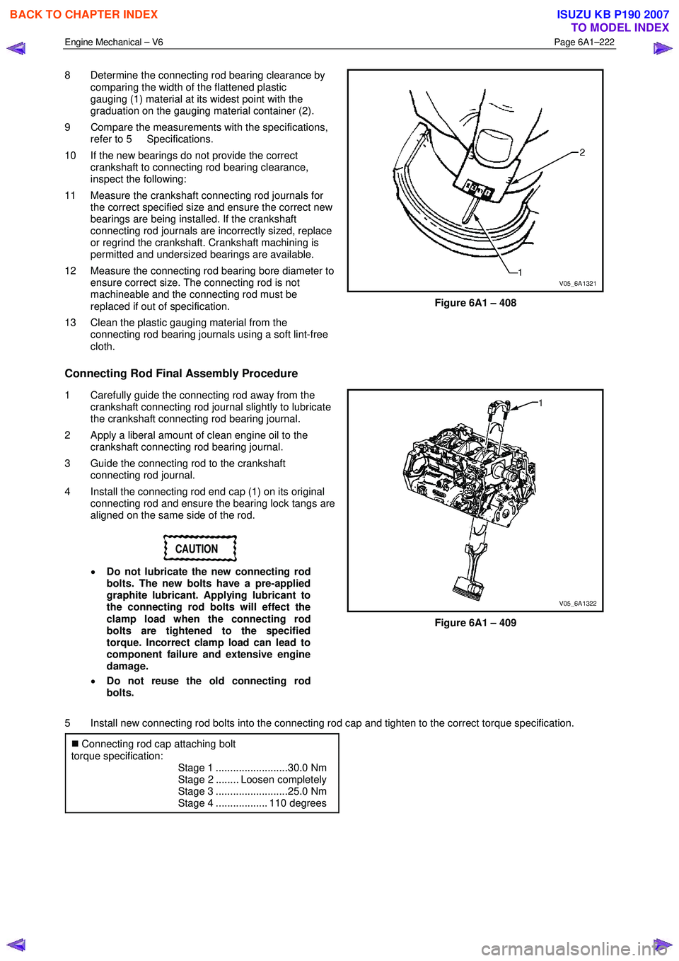
8 Determine the connecting rod bearing clearance by
comparing the width of the flattened plastic
gauging (1) material at its widest point with the
graduation on the gauging material container (2).
9 Compare the measurements with the specifications, refer to 5 Specifications.
10 If the new bearings do not provide the correct crankshaft to connecting rod bearing clearance,
inspect the following:
11 Measure the crankshaft connecting rod journals for the correct specified size and ensure the correct new
bearings are being installed. If the crankshaft
connecting rod journals are incorrectly sized, replace
or regrind the crankshaft. Crankshaft machining is
permitted and undersized bearings are available.
12 Measure the connecting rod bearing bore diameter to ensure correct size. The connecting rod is not
machineable and the connecting rod must be
replaced if out of specification.
13 Clean the plastic gauging material from the connecting rod bearing journals using a soft lint-free
cloth.
Figure 6A1 – 408
Connecting Rod Final Assembly Procedure
1 Carefully guide the connecting rod away from the crankshaft connecting rod journal slightly to lubricate
the crankshaft connecting rod bearing journal.
2 Apply a liberal amount of clean engine oil to the crankshaft connecting rod bearing journal.
3 Guide the connecting rod to the crankshaft connecting rod journal.
4 Install the connecting rod end cap (1) on its original connecting rod and ensure the bearing lock tangs are
aligned on the same side of the rod.
CAUTION
• Do not lubricate the new connecting rod
bolts. The new bolts have a pre-applied
graphite lubricant. Applying lubricant to
the connecting rod bolts will effect the
clamp load when the connecting rod
bolts are tightened to the specified
torque. Incorrect clamp load can lead to
component failure and extensive engine
damage.
• Do not reuse the old connecting rod
bolts.
Figure 6A1 – 409
5 Install new connecting rod bolts into the connecting rod cap and tighten to the correct torque specification. �„ Connecting rod cap attaching bolt
torque specification:
Stage 1 .........................30.0 Nm
Stage 2 ........ Loosen completely
Stage 3 .........................25.0 Nm
Stage 4 .................. 110 degrees
BACK TO CHAPTER INDEX
TO MODEL INDEX
ISUZU KB P190 2007
Page 2708 of 6020
Engine Mechanical – V6 Page 6A1–229
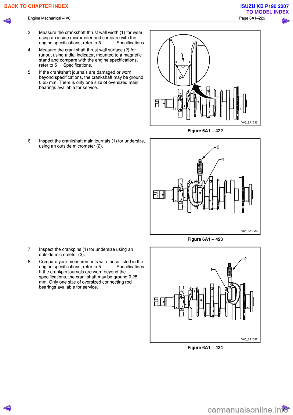
3 Measure the crankshaft thrust wall width (1) for wear
using an inside micrometer and compare with the
engine specifications, refer to 5 Specifications.
4 Measure the crankshaft thrust wall surface (2) for runout using a dial indicator, mounted to a magnetic
stand and compare with the engine specifications,
refer to 5 Specifications.
5 If the crankshaft journals are damaged or worn beyond specifications, the crankshaft may be ground
0.25 mm. There is only one size of oversized main
bearings available for service.
Figure 6A1 – 422
6 Inspect the crankshaft main journals (1) for undersize, using an outside micrometer (2).
Figure 6A1 – 423
7 Inspect the crankpins (1) for undersize using an outside micrometer (2).
8 Compare your measurements with those listed in the engine specifications, refer to 5 Specifications.
If the crankpin journals are worn beyond the
specifications, the crankshaft may be ground 0.25
mm. Only one size of oversized connecting rod
bearings available for service.
Figure 6A1 – 424
BACK TO CHAPTER INDEX
TO MODEL INDEX
ISUZU KB P190 2007
Page 2711 of 6020

Engine Mechanical – V6 Page 6A1–232
NOTE
Do not rotate the crankshaft.
9 Allow the assembly to sit for 2 minutes.
10 Remove the crankshaft bearing cap side bolts.
11 Remove the crankshaft bearing cap outer bolts (2).
12 Remove the crankshaft bearing cap inner bolts (1).
13 Install the crankshaft main bearing cap remover Tool No. J-41818 as previously described and remove the
crankshaft bearing cap.
14 Repeat steps 10 to 13 for the remaining crankshaft bearing caps.
Figure 6A1 – 430
15 Determine the crankshaft bearing clearance by comparing the width of the flattened plastic gauging
material (1) at its widest point with the graduation on
the gauging material scale (2).
16 Compare the measurements listed in the specifications, refer to 5 Specifications. If the
new bearings do not provide the correct crankshaft to
bearing clearance, inspect the following:
17 Measure the crankshaft journals for the correct specified size and ensure new bearings are being
installed. If the crankshaft journals are incorrectly
sized, replace or regrind the crankshaft. Crankshaft
machining is permitted and undersized bearings are
available.
18 Measure the engine block crankshaft bearing bore diameter to ensure correct size. The engine block
crankshaft bearing bore is not machineable and the
block must be replaced if out of specification.
19 Clean the plastic gauging material from the crankshaft bearing journals with a soft, lint-free cloth.
Figure 6A1 – 431
BACK TO CHAPTER INDEX
TO MODEL INDEX
ISUZU KB P190 2007
Page 2767 of 6020
Engine Mechanical – V6 Page 6A1–288
5 Specifications
General
Engine Type.................................................................................................................... ..... V6
Bank Angle ..................................................................................................................... .... 60°
Displacement ............................................................................................ 3.6 litre (3,565 cm3)
Bore ........................................................................................................................... .... 94 mm
Stroke ......................................................................................................................... 85.6 mm
Compression Ratio ......................................................................................................... 10.2: 1
Cranking Speed at 40 °C .............................................................................................80 r.p.m.
Spark Plug Gap ............................................................................................................ 1.1 m m
Firing Order............................................................................................................. 1-2-3- 4-5-6
Cylinder Block
Cylinder Bore Diameter ........................................................................... 93.992 – 94.008 mm
Cylinder Out-of-Round – Production Maximum ........................................................ 0.013 mm
Crankshaft Main bearing bore Diameter .................................................. 72.867 – 72.881 mm
Cylinder Head Deck Surface Flatness ........................................................................ 0.05 mm
Crankshaft
Connecting Rod Journal Diameter ........................................................... 55.992 – 56.008 mm
Connecting Rod Journal Out-of-Round..................................................................... 0.005 mm
Connecting Rod Journal Taper ................................................................................ .0.005 mm
Connecting Rod Journal Width (Production)........................................................... 22.000 mm
Connecting Rod Journal Width (Service limit).......................................... 21.920 – 22.080 mm
Crankshaft End Play .................................................................................... 0.100 – 0.330 mm
Crankshaft Main Bearing Clearance ............................................................ 0.010 – 0.060 mm
Crankshaft Main Journal Diameter ......................................................... .67.992 – 68.008 mm
Crankshaft Main Journal Out-of-Round .................................................................... 0.005 mm
Crankshaft Main Journal Taper................................................................................ .0.005 mm
Crankshaft Main Journal Width, #2, 4 (Production) ....................................................... 24 mm
Crankshaft Main Journal Width, #2, 4 (Service)....................................... 23.900 – 24.100 mm
Crankshaft Main Journal Width, #3 (Production) .................................................... 24.400 mm
Crankshaft Main Journal Width, #3 (Service) .......................................... 24.360 – 24.440 mm
Crankshaft Main Journal Thrust Wall Runout .............................................. 0.000 – 0.040 mm
Crankshaft Main Journal Thrust Wall Square .............................................. 0.000 – 0.010 mm
Crankshaft Rear Flange Runout ............................................................................... 0.025 mm
Crankshaft Reluctor Ring Runout - Maximum........................................................... 1.500 mm
Crankshaft Thrust Bearing Clearance.......................................................... 0.076 – 0.305 mm
Crankshaft Thrust Surface Runout ........................................................................... 0.040 mm
Crankshaft Thrust Surface – Height Diameter ........................................................ 95.000 mm
Connecting Rod
Connecting Rod Length - Bore Centre-to-Centre.................................................. 150.400 mm
Connecting Rod Bore Diameter - Bearing End ........................................ 59.620 – 59.636 mm
Connecting Rod Bore Diameter - Pin End ............................................... 24.007 – 24.021 mm
Connecting Rod Width ........................................................................................... 21.775 mm
Connecting Rod Side Clearance.................................................................. 0.095 – 0.355 mm
Connecting Rod Bearing Clearance ............................................................ 0.010 – 0.070 mm
Piston
Piston Diameter ....................................................................................... 93.956 – 93.974 mm
Piston Pin Bore Diameter ........................................................................ 24.005 – 24.009 mm
Piston Ring Groove Width - First (Top) Compression Ring ......................... 1.220 – 1.240 mm
Piston Ring Groove Width - Second Compression Ring .............................. 1.510 – 1.530 mm
BACK TO CHAPTER INDEX
TO MODEL INDEX
ISUZU KB P190 2007