2007 ISUZU KB P190 width
[x] Cancel search: widthPage 2321 of 6020
ENGINE DRIVEABILITY AND EMISSIONS 6E–151
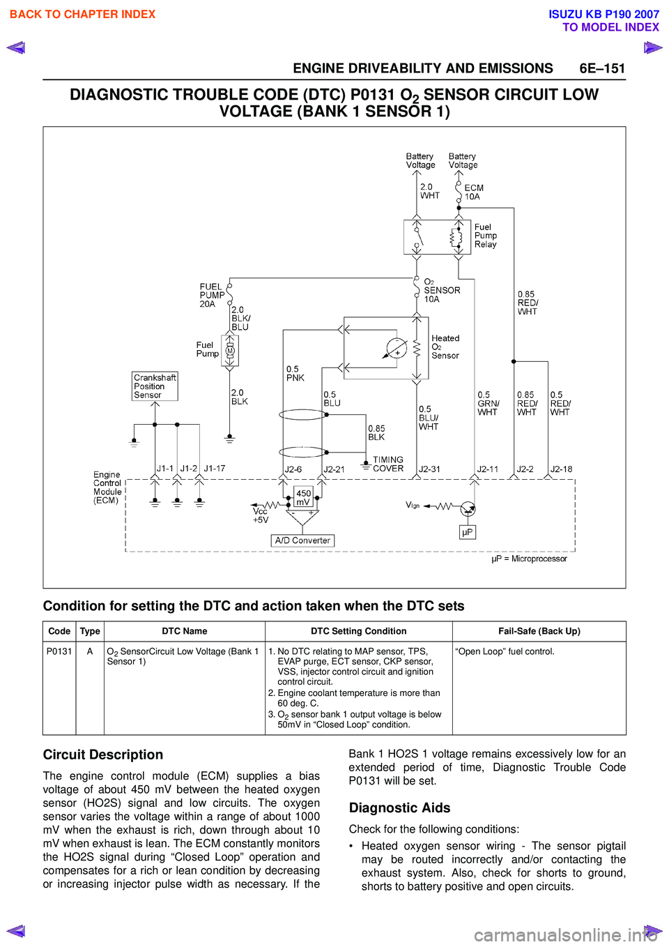
DIAGNOSTIC TROUBLE CODE (DTC) P0131 O2 SENSOR CIRCUIT LOW
VOLTAGE (BANK 1 SENSOR 1)
Condition for setting the DTC and action taken when the DTC sets
Circuit Description
The engine control module (ECM) supplies a bias
voltage of about 450 mV between the heated oxygen
sensor (HO2S) signal and low circuits. The oxygen
sensor varies the voltage within a range of about 1000
mV when the exhaust is rich, down through about 10
mV when exhaust is lean. The ECM constantly monitors
the HO2S signal during “Closed Loop” operation and
compensates for a rich or lean condition by decreasing
or increasing injector pulse width as necessary. If the Bank 1 HO2S 1 voltage remains excessively low for an
extended period of time, Diagnostic Trouble Code
P0131 will be set.
Diagnostic Aids
Check for the following conditions:
• Heated oxygen sensor wiring - The sensor pigtail may be routed incorrectly and/or contacting the
exhaust system. Also, check for shorts to ground,
shorts to battery positive and open circuits.
Code Type DTC Name DTC Setting Condition Fail-Safe (Back Up)
P0131 A O
2 SensorCircuit Low Voltage (Bank 1
Sensor 1) 1. No DTC relating to MAP sensor, TPS,
EVAP purge, ECT sensor, CKP sensor,
VSS, injector control circuit and ignition
control circuit.
2. Engine coolant temperature is more than 60 deg. C.
3. O
2 sensor bank 1 output voltage is below
50mV in “Closed Loop” condition. “Open Loop” fuel control.
BACK TO CHAPTER INDEX
TO MODEL INDEX
ISUZU KB P190 2007
Page 2325 of 6020

ENGINE DRIVEABILITY AND EMISSIONS 6E–155
DIAGNOSTIC TROUBLE CODE (DTC) P0132 O2 SENSOR CIRCUIT HIGH
VOLTAGE (BANK 1 SENSOR 1)
Condition for setting the DTC and action taken when the DTC sets
Circuit Description
The engine control module (ECM) supplies a bias
voltage of about 450 mV between the heated oxygen
sensor (HO2S) signal and low circuits. The oxygen
sensor varies the voltage within a range of about 1000
mV when the exhaust is rich, down through about 10
mV when exhaust is lean. The ECM constantly monitors
the HO2S signal during “Closed Loop” operation and
compensates for a rich or lean condition by decreasing
or increasing injector pulse width as necessary. If the Bank 1 HO2S 1 voltage remains excessively high for an
extended period of time, Diagnostic Trouble Code
P0132 will be set.
Diagnostic Aids
Check the following items:
• Fuel pressure - The system will go rich if pressure is too high. The ECM can compensate for some
increase. However, if fuel pressure is too high, a
Diagnostic Trouble Code P0132 may be set. Refer to
Code Type DTC Name DTC Setting Condition Fail-Safe (Back Up)
P0132 A O
2 Sensor Circuit High Voltage (Bank 1
Sensor 1) 1. No DTC relating to MAP sensor, TPS,
EVAP purge, ECT sensor, CKP sensor,
VSS, injector control circuit and ignition
control circuit.
2. Engine coolant temperature is more than 60 deg. C.
3. O
2 sensor bank 1 output voltage is more
than 952mV in “Closed Loop” condition. “Open Loop” fuel control.
BACK TO CHAPTER INDEX
TO MODEL INDEX
ISUZU KB P190 2007
Page 2329 of 6020
ENGINE DRIVEABILITY AND EMISSIONS 6E–159
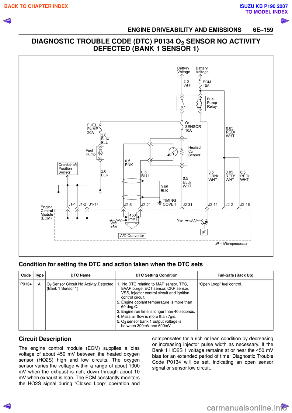
DIAGNOSTIC TROUBLE CODE (DTC) P0134 O2 SENSOR NO ACTIVITY
DEFECTED (BANK 1 SENSOR 1)
Condition for setting the DTC and action taken when the DTC sets
Circuit Description
The engine control module (ECM) supplies a bias
voltage of about 450 mV between the heated oxygen
sensor (HO2S) high and low circuits. The oxygen
sensor varies the voltage within a range of about 1000
mV when the exhaust is rich, down through about 10
mV when exhaust is lean. The ECM constantly monitors
the HO2S signal during “Closed Loop” operation and compensates for a rich or lean condition by decreasing
or increasing injector pulse width as necessary. If the
Bank 1 HO2S 1 voltage remains at or near the 450 mV
bias for an extended period of time, Diagnostic Trouble
Code P0134 will be set, indicating an open sensor
signal or sensor low circuit.
Code Type DTC Name DTC Setting Condition Fail-Safe (Back Up)
P0134 A O
2 Sensor Circuit No Activity Detected
(Bank 1 Sensor 1) 1. No DTC relating to MAP sensor, TPS,
EVAP purge, ECT sensor, CKP sensor,
VSS, injector control circuit and ignition
control circuit.
2. Engine coolant temperature is more than 60 deg.C.
3. Engine run time is longer than 40 seconds.
4. Mass air flow is more than 7g/s.
5. O
2 sensor bank 1 output voltage is
between 300mV and 600mV. “Open Loop” fuel control.
BACK TO CHAPTER INDEX
TO MODEL INDEX
ISUZU KB P190 2007
Page 2525 of 6020
Engine Mechanical – V6 Page 6A1–46
7 Misalignment of the pulleys may be caused by one of the following:
• Incorrect mounting of an accessory drive component,
• Incorrect installation of an accessory drive pulley or,
• Bent or damaged pulley.
Test for a misaligned pulley using a straight edge in the pulley grooves across 2 or 3 pulleys. If a misaligned pulley is found, refer to the relevant component service information for the correct installation and removal procedures.
8 This test is to confirm the pulleys are the correct diameter and/or width. Using a known good vehicle, compare the pulley sizes.
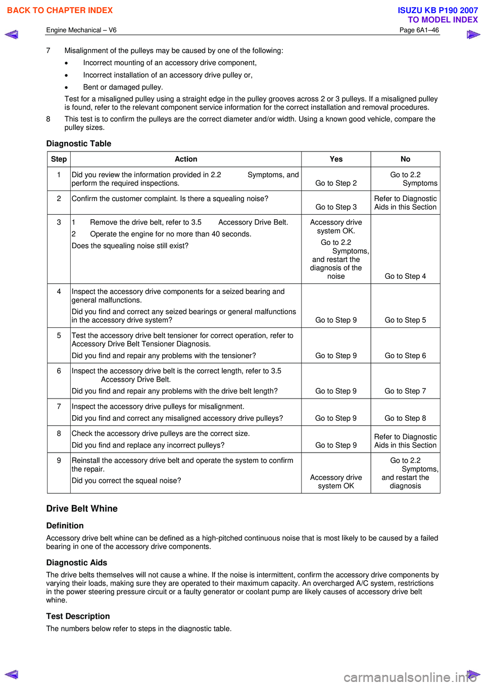
Diagnostic Table
Step Action Yes No
1 Did you review the information provided in 2.2 Symptoms, and
perform the required inspections. Go to Step 2 Go to 2.2
Symptoms
2 Confirm the customer complaint. Is there a squealing noise? Go to Step 3 Refer to Diagnostic
Aids in this Section
3 1 Remove the drive belt, refer to 3.5 Accessory Drive Belt.
2 Operate the engine for no more than 40 seconds.
Does the squealing noise still exist? Accessory drive
system OK.
Go to 2.2
Symptoms, and restart the
diagnosis of the noise Go to Step 4
4 Inspect the accessory drive components for a seized bearing and
general malfunctions.
Did you find and correct any seized bearings or general malfunctions
in the accessory drive system? Go to Step 9 Go to Step 5
5 Test the accessory drive belt tensioner for correct operation, refer to
Accessory Drive Belt Tensioner Diagnosis.
Did you find and repair any problems with the tensioner? Go to Step 9 Go to Step 6
6 Inspect the accessory drive belt is the correct length, refer to 3.5
Accessory Drive Belt.
Did you find and repair any problems with the drive belt length? Go to Step 9 Go to Step 7
7 Inspect the accessory drive pulleys for misalignment.
Did you find and correct any misaligned accessory drive pulleys? Go to Step 9 Go to Step 8
8 Check the accessory drive pulleys are the correct size. Did you find and replace any incorrect pulleys? Go to Step 9 Refer to Diagnostic
Aids in this Section
9 Reinstall the accessory drive belt and operate the system to confirm
the repair.
Did you correct the squeal noise? Accessory drive
system OK Go to 2.2
Symptoms, and restart the diagnosis
Drive Belt Whine
Definition
Accessory drive belt whine can be defined as a high-pitched continuous noise that is most likely to be caused by a failed
bearing in one of the accessory drive components.
Diagnostic Aids
The drive belts themselves will not cause a whine. If the noise is intermittent, confirm the accessory drive components by
varying their loads, making sure they are operated to their maximum capacity. An overcharged A/C system, restrictions
in the power steering pressure circuit or a faulty generator or coolant pump are likely causes of accessory drive belt
whine.
Test Description
The numbers below refer to steps in the diagnostic table.
BACK TO CHAPTER INDEX
TO MODEL INDEX
ISUZU KB P190 2007
Page 2531 of 6020
Engine Mechanical – V6 Page 6A1–52
Diagnostic Aids
Excessive wear of a drive belt is usually caused by an incorrect installation or an incorrect drive belt fitted. Minor pulley
misalignment will not cause excessive wear, but will cause the drive belt to fall off. Major pulley misalignment may cause
excessive wear, but would also result in the drive belt falling off.
Test Description
The numbers below refer to steps in the diagnostic table.
2 Confirms the drive belt is correctly installed onto all of the accessory drive system pulleys. W ear on the drive belt may be caused by incorrectly positioning the drive belt by one or more grooves to a particular pulley.
3 The installation of the drive belt that is the incorrect width will cause wear on the drive belt. The drive belt ribs should match all the grooves on all the pulleys in the accessory drive system.
4 Confirms the drive belt is not contacting any parts of the engine or body while the engine is running. There should be sufficient clearance when the accessory drive component loads varies. The drive belt should not come into
contact with any engine or body parts.
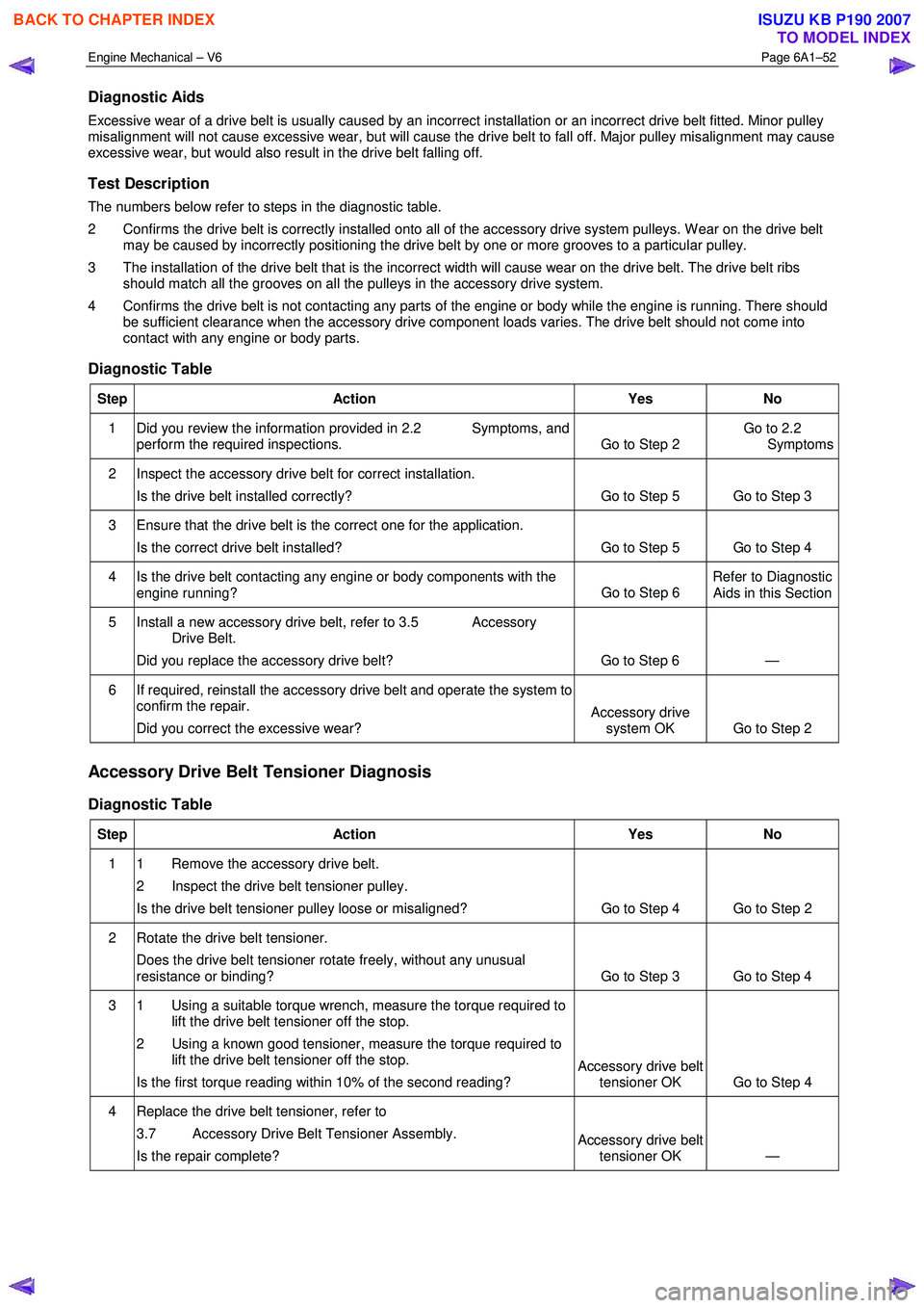
Diagnostic Table
Step Action Yes No
1 Did you review the information provided in 2.2 Symptoms, and
perform the required inspections. Go to Step 2 Go to 2.2
Symptoms
2 Inspect the accessory drive belt for correct installation.
Is the drive belt installed correctly? Go to Step 5 Go to Step 3
3 Ensure that the drive belt is the correct one for the application. Is the correct drive belt installed? Go to Step 5 Go to Step 4
4 Is the drive belt contacting any engine or body components with the engine running? Go to Step 6 Refer to Diagnostic
Aids in this Section
5 Install a new accessory drive belt, refer to 3.5 Accessory Drive Belt.
Did you replace the accessory drive belt? Go to Step 6 —
6 If required, reinstall the accessory drive belt and operate the system to confirm the repair.
Did you correct the excessive wear? Accessory drive
system OK Go to Step 2
Accessory Drive Belt Tensioner Diagnosis
Diagnostic Table
Step Action Yes No
1 1 Remove the accessory drive belt.
2 Inspect the drive belt tensioner pulley.
Is the drive belt tensioner pulley loose or misaligned? Go to Step 4 Go to Step 2
2 Rotate the drive belt tensioner.
Does the drive belt tensioner rotate freely, without any unusual
resistance or binding? Go to Step 3 Go to Step 4
3 1 Using a suitable torque wrench, measure the torque required to
lift the drive belt tensioner off the stop.
2 Using a known good tensioner, measure the torque required to lift the drive belt tensioner off the stop.
Is the first torque reading within 10% of the second reading?
Accessory drive belt tensioner OK Go to Step 4
4 Replace the drive belt tensioner, refer to
3.7 Accessory Drive Belt Tensioner Assembly.
Is the repair complete?
Accessory drive belt tensioner OK —
BACK TO CHAPTER INDEX
TO MODEL INDEX
ISUZU KB P190 2007
Page 2631 of 6020
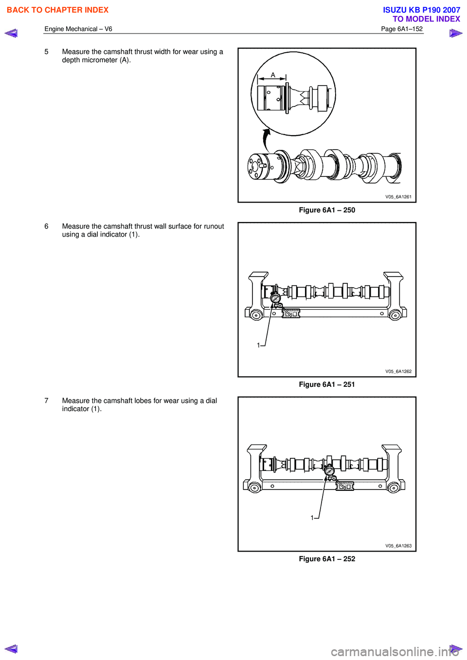
Engine Mechanical – V6 Page 6A1–152
5 Measure the camshaft thrust width for wear using a
depth micrometer (A).
Figure 6A1 – 250
6 Measure the camshaft thrust wall surface for runout using a dial indicator (1).
Figure 6A1 – 251
7 Measure the camshaft lobes for wear using a dial indicator (1).
Figure 6A1 – 252
BACK TO CHAPTER INDEX
TO MODEL INDEX
ISUZU KB P190 2007
Page 2638 of 6020
Engine Mechanical – V6 Page 6A1–159
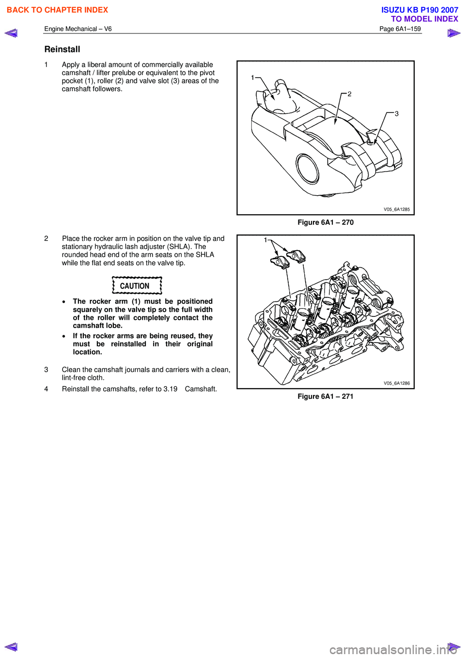
Reinstall
1 Apply a liberal amount of commercially available
camshaft / lifter prelube or equivalent to the pivot
pocket (1), roller (2) and valve slot (3) areas of the
camshaft followers.
Figure 6A1 – 270
2 Place the rocker arm in position on the valve tip and stationary hydraulic lash adjuster (SHLA). The
rounded head end of the arm seats on the SHLA
while the flat end seats on the valve tip.
CAUTION
• The rocker arm (1) must be positioned
squarely on the valve tip so the full width
of the roller will completely contact the
camshaft lobe.
• If the rocker arms are being reused, they
must be reinstalled in their original
location.
3 Clean the camshaft journals and carriers with a clean, lint-free cloth.
4 Reinstall the camshafts, refer to 3.19 Camshaft.
Figure 6A1 – 271
BACK TO CHAPTER INDEX
TO MODEL INDEX
ISUZU KB P190 2007
Page 2650 of 6020
Engine Mechanical – V6 Page 6A1–171
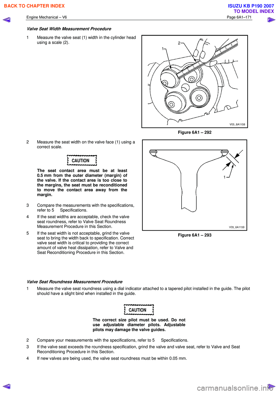
Valve Seat Width Measurement Procedure
1 Measure the valve seat (1) width in the cylinder head
using a scale (2).
Figure 6A1 – 292
2 Measure the seat width on the valve face (1) using a correct scale.
CAUTION
The seat contact area must be at least
0.5 mm from the outer diameter (margin) of
the valve. If the contact area is too close to
the margins, the seat must be reconditioned
to move the contact area away from the
margin.
3 Compare the measurements with the specifications, refer to 5 Specifications.
4 If the seat widths are acceptable, check the valve seat roundness, refer to Valve Seat Roundness
Measurement Procedure in this Section.
5 If the seat width is not acceptable, grind the valve seat to bring the width back to specification. Correct
valve seat width is critical to providing the correct
amount of valve heat dissipation, refer to Valve and
Seat Reconditioning Procedure in this Section.
Figure 6A1 – 293
Valve Seat Roundness Measurement Procedure
1 Measure the valve seat roundness using a dial indicator attached to a tapered pilot installed in the guide. The pilot should have a slight bind when installed in the guide.
CAUTION
The correct size pilot must be used. Do not
use adjustable diameter pilots. Adjustable
pilots may damage the valve guides.
2 Compare your measurements with the specifications, refer to 5 Specifications.
3 If the valve seat exceeds the roundness specification, grind the valve and valve seat, refer to Valve and Seat Reconditioning Procedure in this Section.
4 If new valves are being used, the valve seat roundness must be within 0.05 mm.
BACK TO CHAPTER INDEX
TO MODEL INDEX
ISUZU KB P190 2007