2007 ISUZU KB P190 width
[x] Cancel search: widthPage 2122 of 6020
6C-4 ENGINE FUEL (C24SE)
Fuel Metering
Engine Control Module (ECM) is in complete control of this fuel
delivery system during normal driving conditions.
The intake manifold function, like that of a diesel, is used onl
y
to let air into the engine. The fuel is injected by separate
injectors that are mounted over the intake manifold.
The Manifold Absolute Pressure (MAP) sensor measures the
changes in the intake manifold pressure which result from
engine load and speed changes, which the MAP senso
r
converts to a voltage output.
This sensor generates the voltage to change corresponding to
the flow of the air drawn into the engine.
The changing voltage is transformed into an electric signal and
provided to the ECM.
W ith receipt of the signals sent from the MAP sensor, Intake
Air Temperature sensor and others, the ECM determines an
appropriate fuel injection pulse width feeding such information
to the fuel injector valves to effect an appropriate air/fuel ratio.
The Multiport Fuel Injection system utilizes an injection system
where the injectors turn on at every crankshaft revolution. The
ECM controls the injector on time so that the correct amount o
f
fuel is metered depending on driving conditions.
Two interchangeable "O" rings are used on the injector that
must be replaced when the injectors are removed.
The fuel rail is attached to the top of the intake manifold and
supplies fuel to all the injectors.
Fuel is recirculated through the rail continually while the engine
is running. This removes air and vapors from the fuel as well
as keeping the fuel cool during hot weather operation.
The fuel pressure control valve that is mounted on the fuel rail
maintains a pressure differential across the injectors under all
operating conditions. It is accomplished by controlling the
amount of fuel that is recirculated back to the fuel tank based
on engine demand.
See Section "Driveability and Emission" for more information
and diagnosis.
BACK TO CHAPTER INDEX
TO MODEL INDEX
ISUZU KB P190 2007
Page 2221 of 6020
ENGINE DRIVEABILITY AND EMISSIONS 6E–51
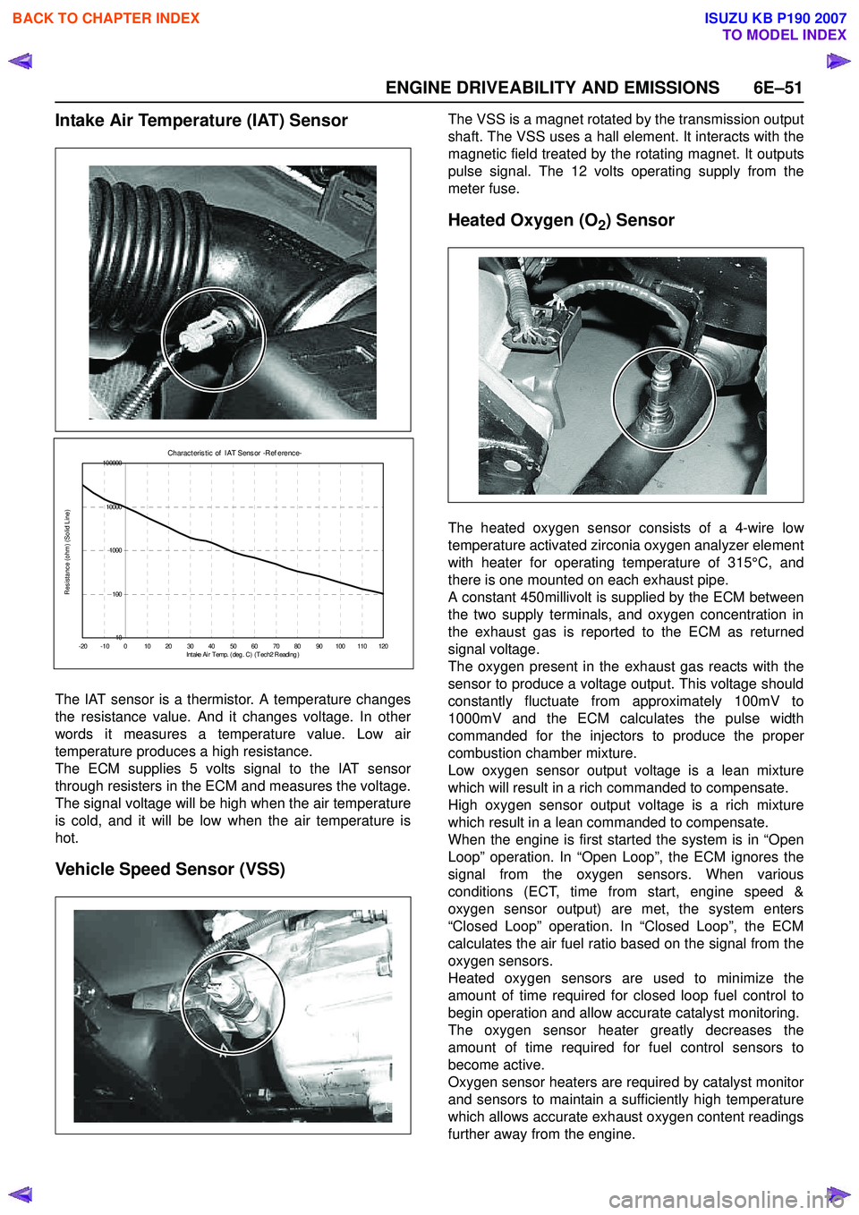
Intake Air Temperature (IAT) Sensor
The IAT sensor is a thermistor. A temperature changes
the resistance value. And it changes voltage. In other
words it measures a temperature value. Low air
temperature produces a high resistance.
The ECM supplies 5 volts signal to the IAT sensor
through resisters in the ECM and measures the voltage.
The signal voltage will be high when the air temperature
is cold, and it will be low when the air temperature is
hot.
Vehicle Speed Sensor (VSS)
The VSS is a magnet rotated by the transmission output
shaft. The VSS uses a hall element. It interacts with the
magnetic field treated by the rotating magnet. It outputs
pulse signal. The 12 volts operating supply from the
meter fuse.
Heated Oxygen (O2) Sensor
The heated oxygen sensor consists of a 4-wire low
temperature activated zirconia oxygen analyzer element
with heater for operating temperature of 315°C, and
there is one mounted on each exhaust pipe.
A constant 450millivolt is supplied by the ECM between
the two supply terminals, and oxygen concentration in
the exhaust gas is reported to the ECM as returned
signal voltage.
The oxygen present in the exhaust gas reacts with the
sensor to produce a voltage output. This voltage should
constantly fluctuate from approximately 100mV to
1000mV and the ECM calculates the pulse width
commanded for the injectors to produce the proper
combustion chamber mixture.
Low oxygen sensor output voltage is a lean mixture
which will result in a rich commanded to compensate.
High oxygen sensor output voltage is a rich mixture
which result in a lean commanded to compensate.
When the engine is first started the system is in “Open
Loop” operation. In “Open Loop”, the ECM ignores the
signal from the oxygen sensors. When various
conditions (ECT, time from start, engine speed &
oxygen sensor output) are met, the system enters
“Closed Loop” operation. In “Closed Loop”, the ECM
calculates the air fuel ratio based on the signal from the
oxygen sensors.
Heated oxygen sensors are used to minimize the
amount of time required for closed loop fuel control to
begin operation and allow accurate catalyst monitoring.
The oxygen sensor heater greatly decreases the
amount of time required for fuel control sensors to
become active.
Oxygen sensor heaters are required by catalyst monitor
and sensors to maintain a sufficiently high temperature
which allows accurate exhaust oxygen content readings
further away from the engine.
Charac t eris t ic of I AT Sens or -R ef erenc e-
10
100
1000
10000
100000
- 20 - 10 0 10 20 30 40 50 60 70 80 90 100 110 120 Intake Ai r T emp. ( deg . C ) ( T ec h2 R eadi ng )
Resistance (ohm) (Solid Line)
BACK TO CHAPTER INDEX
TO MODEL INDEX
ISUZU KB P190 2007
Page 2227 of 6020
ENGINE DRIVEABILITY AND EMISSIONS 6E–57
GENERAL DESCRIPTION FOR
EVAPORATIVE EMISSION SYSTEM
EVAP Emission Control System Purpose
The basic evaporative emission control system used on
the charcoal canister storage method. The method
transfers fuel vapor from the fuel tank to an activated
carbon (charcoal) storage devise to hold the vapors
when the vehicle is not operating.
The canister is located on the rear axle housing by the
frame cross-member.
When the engine is running, the fuel vapor is purged
from the carbon element by intake air flow and
consumed in the normal combustion process.
EVAP Emission Control System Operation
The EVAP canister purge is controlled by a solenoid
valve that allows the manifold vacuum to purge the
canister. The engine control module (ECM) supplies a
ground to energize the solenoid valve (purge on). The
EVAP purge solenoid control is pulse-width modulated
(PWM) (turned on and off several times a second). The
duty cycle (pulse width) is determined by engine
operating conditions including load, throttle position,
coolant temperature and ambient temperature. The duty
cycle is calculated by the ECM. the output is
commanded when the appropriate conditions have
been met. These conditions are:
• The engine is fully warmed up.
• The engine has been running for a specified time.
• The IAT reading is above 10°C (50°F).
• Purge/Vacuum Hoses. Made of rubber compounds, these hoses route the gasoline fumes from their
sources to the canister and from the canister to the
intake air flow.
• EVAP Canister. Mounted on a bracket ahead of the fuel tank, the canister stores fuel vapors until the
ECM determined that engine conditions are right for
them to be removed and burned.
Poor idle, stalling and Poor driveability can be caused
by:
• A malfunctioning purge solenoid.
• A damaged canister.
• Hoses that are split, cracked, or not connected properly.
System Fault Detection
The EVAP leak detection strategy is based on applying
vacuum to the EVAP system and monitoring vacuum
decay. At an appropriate time, the EVAP purge solenoid
is turned “ON,” allowing the engine vacuum to draw a
small vacuum on the entire evaporative emission
system.
After the desired vacuum level has been achieved, the
EVAP purge solenoid is turned “OFF,” sealing the
system. A leak is detected by monitoring for a decrease
in vacuum level over a given time period, all other
variables remaining constant.
If the desired vacuum level cannot be achieved in the
test described above, a large leak or a faulty EVAP
purge control solenoid valve is indicated.
Leaks can be caused by the following conditions:
• Missing or faulty fuel cap
• Disconnected, damaged, pinched, or blocked EVAP purge line
• Disconnected, damaged, pinched, or blocked fuel tank vapor line
• Disconnected or faulty EVAP purge control solenoid valve
• Open ignition feed circuit to the purge solenoid
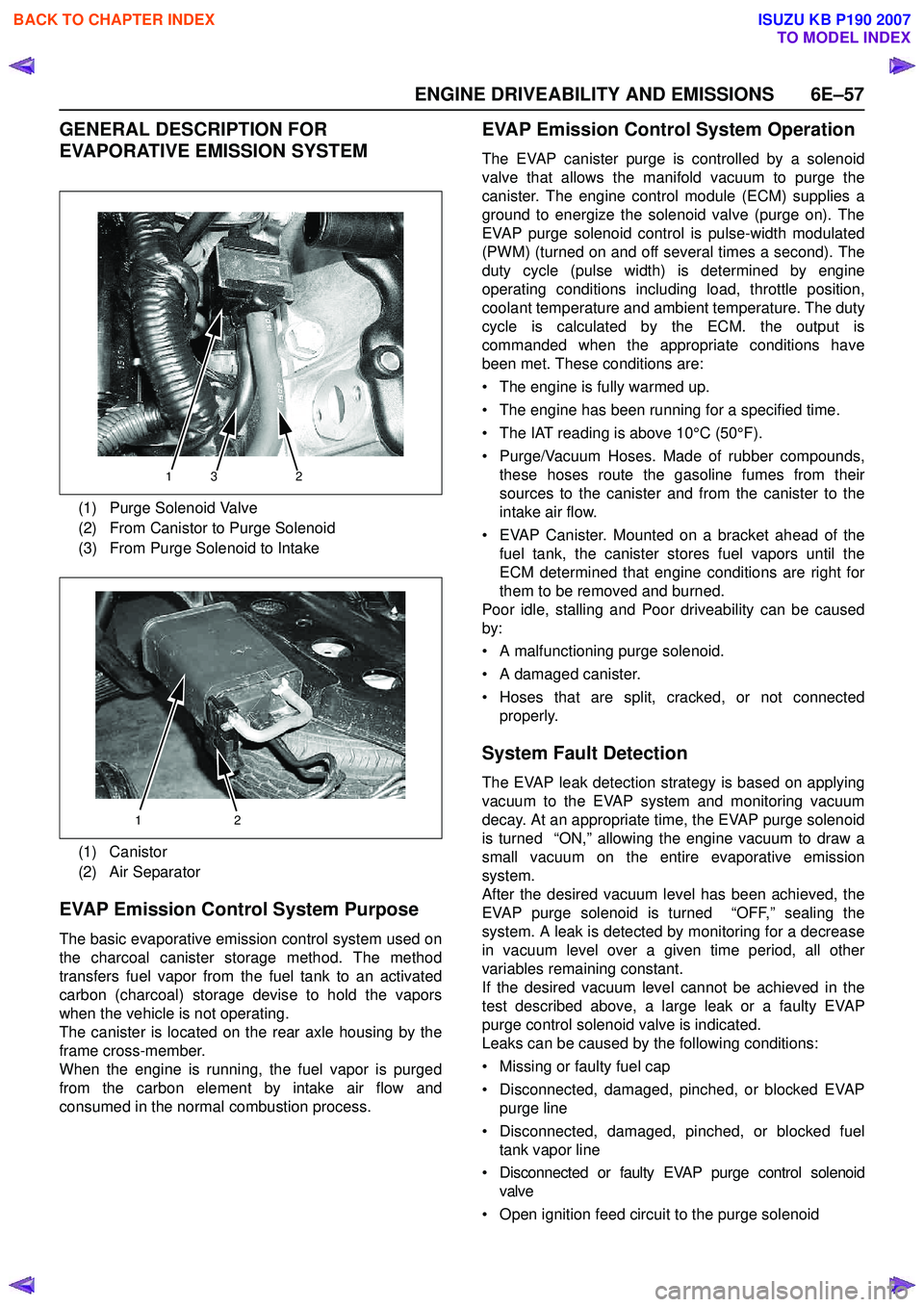
(1) Purge Solenoid Valve
(2) From Canistor to Purge Solenoid
(3) From Purge Solenoid to Intake
(1) Canistor
(2) Air Separator
132
12
BACK TO CHAPTER INDEX
TO MODEL INDEX
ISUZU KB P190 2007
Page 2228 of 6020
6E–58 ENGINE DRIVEABILITY AND EMISSIONS
• Damaged EVAP canister
• Leaking fuel sender assembly O-ring
• Leaking fuel tank or fuel filler neck
The ECM supplies a ground to energize the purge
control solenoid valve (purge “ON” ). The EVAP purge
control is turned “ON” and “OFF,” several times a
second. The duty cycle (pulse width) is determined by
engine operating conditions including load, throttle
position, coolant temperature and ambient temperature.
The duty cycle is calculated by the ECM and the output
is commanded when the appropriate conditions have
been met.
The system checks for conditions that cause the EVAP
system to purge continuously by commanding the EVAP
purge solenoid “OFF”, EVAP purge solenoid duty ratio
“0%”. If fuel tank vacuum level increases during the test,
a continuous purge flow condition is indicated. This can
be caused by the following conditions:
• EVAP purge solenoid leaking
• EVAP purge and engine vacuum lines switched at the EVAP purge control solenoid valve
• EVAP purge control solenoid valve driver circuit grounded
BACK TO CHAPTER INDEX
TO MODEL INDEX
ISUZU KB P190 2007
Page 2242 of 6020
6E–72 ENGINE DRIVEABILITY AND EMISSIONS
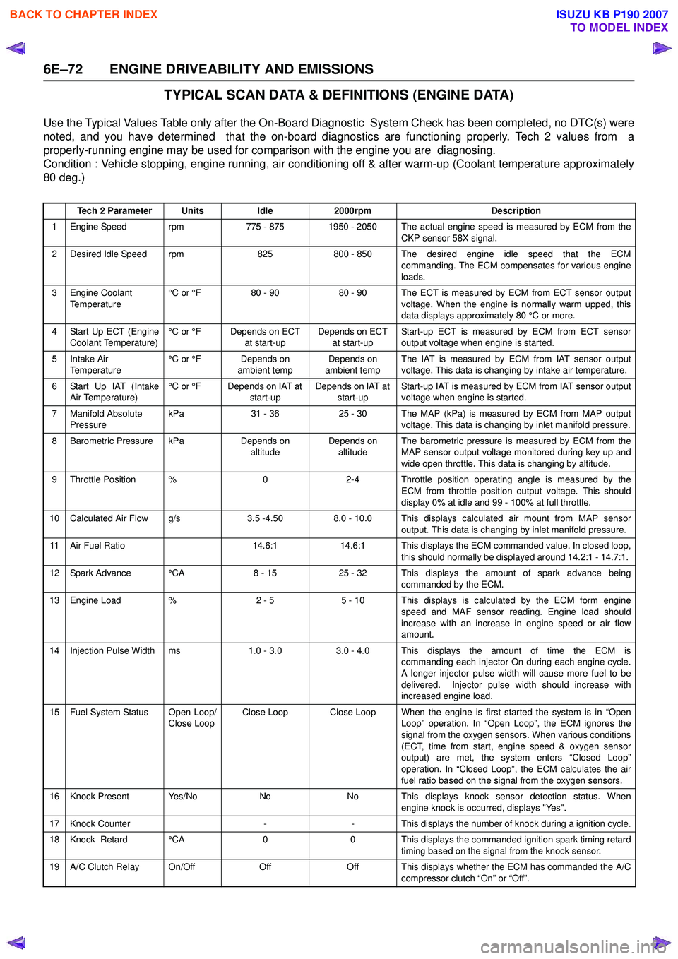
TYPICAL SCAN DATA & DEFINITIONS (ENGINE DATA)
Use the Typical Values Table only after the On-Board Diagnostic System Check has been completed, no DTC(s) were
noted, and you have determined that the on-board diagnostics are functioning properly. Tech 2 values from a
properly-running engine may be used for comparison with the engine you are diagnosing.
Condition : Vehicle stopping, engine running, air conditioning off & after warm-up (Coolant temperature approximately
80 deg.)
Tech 2 ParameterUnitsIdle2000rpmDescription
1 Engine Speed rpm775 - 8751950 - 2050 The actual engine speed is measured by ECM from the
CKP sensor 58X signal.
2 Desired Idle Speed rpm825800 - 850 The desired engine idle speed that the ECMcommanding. The ECM compensates for various engine
loads.
3 Engine Coolant Temperature °C or °F80 - 9080 - 90 The ECT is measured by ECM from ECT sensor output
voltage. When the engine is normally warm upped, this
data displays approximately 80 °C or more.
4 Start Up ECT (Engine Coolant Temperature) °C or °FDepends on ECT
at start-upDepends on ECT at start-up Start-up ECT is measured by ECM from ECT sensor
output voltage when engine is started.
5Intake Air
Temperature °C or °FDepends on
ambient tempDepends on
ambient temp The IAT is measured by ECM from IAT sensor output
voltage. This data is changing by intake air temperature.
6 Start Up IAT (Intake Air Temperature) °C or °FDepends on IAT at
start-upDepends on IAT at start-up Start-up IAT is measured by ECM from IAT sensor output
voltage when engine is started.
7 Manifold Absolute Pressure kPa31 - 3625 - 30The MAP (kPa) is measured by ECM from MAP output
voltage. This data is changing by inlet manifold pressure.
8 Barometric Pressure kPaDepends on altitudeDepends on altitude The barometric pressure is measured by ECM from the
MAP sensor output voltage monitored during key up and
wide open throttle. This data is changing by altitude.
9 Throttle Position %02-4 Throttle position operating angle is measured by the ECM from throttle position output voltage. This should
display 0% at idle and 99 - 100% at full throttle.
10 Calculated Air Flow g/s3.5 -4.508.0 - 10.0 This displays calculated air mount from MAP sensor output. This data is changing by inlet manifold pressure.
11 Air Fuel Ratio14.6:114.6:1 This displays the ECM commanded value. In closed loop,this should normally be displayed around 14.2:1 - 14.7:1.
12 Spark Advance °CA8 - 1525 - 32 This displays the amount of spark advance being commanded by the ECM.
13 Engine Load %2 - 55 - 10 This displays is calculated by the ECM form engine
speed and MAF sensor reading. Engine load should
increase with an increase in engine speed or air flow
amount.
14 Injection Pulse Width ms1.0 - 3.0 3.0 - 4.0 This displays the amount of time the ECM is commanding each injector On during each engine cycle.
A longer injector pulse width will cause more fuel to be
delivered. Injector pulse width should increase with
increased engine load.
15 Fuel System Status Open Loop/ Close LoopClose LoopClose Loop When the engine is first started the system is in “OpenLoop” operation. In “Open Loop”, the ECM ignores the
signal from the oxygen sensors. When various conditions
(ECT, time from start, engine speed & oxygen sensor
output) are met, the system enters “Closed Loop”
operation. In “Closed Loop”, the ECM calculates the air
fuel ratio based on the signal from the oxygen sensors.
16 Knock Present Yes/NoNoNo This displays knock sensor detection status. When engine knock is occurred, displays "Yes".
17 Knock Counter--This displays the number of knock during a ignition cycle.
18 Knock Retard °CA00 This displays the commanded ignition spark timing retard
timing based on the signal from the knock sensor.
19 A/C Clutch Relay On/OffOffOff This displays whether the ECM has commanded the A/C compressor clutch “On” or “Off”.
BACK TO CHAPTER INDEX
TO MODEL INDEX
ISUZU KB P190 2007
Page 2245 of 6020
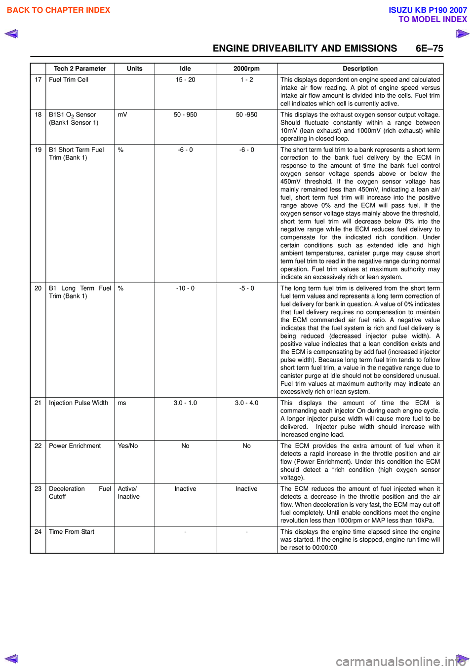
ENGINE DRIVEABILITY AND EMISSIONS 6E–75
17 Fuel Trim Cell15 - 201 - 2 This displays dependent on engine speed and calculatedintake air flow reading. A plot of engine speed versus
intake air flow amount is divided into the cells. Fuel trim
cell indicates which cell is currently active.
18B1S1 O2 Sensor
(Bank1 Sensor 1)mV50 - 95050 -950 This displays the exhaust oxygen sensor output voltage. Should fluctuate constantly within a range between
10mV (lean exhaust) and 1000mV (rich exhaust) while
operating in closed loop.
19B1 Short Term Fuel
Trim (Bank 1)%-6 - 0-6 - 0 The short term fuel trim to a bank represents a short term correction to the bank fuel delivery by the ECM in
response to the amount of time the bank fuel control
oxygen sensor voltage spends above or below the
450mV threshold. If the oxygen sensor voltage has
mainly remained less than 450mV, indicating a lean air/
fuel, short term fuel trim will increase into the positive
range above 0% and the ECM will pass fuel. If the
oxygen sensor voltage stays mainly above the threshold,
short term fuel trim will decrease below 0% into the
negative range while the ECM reduces fuel delivery to
compensate for the indicated rich condition. Under
certain conditions such as extended idle and high
ambient temperatures, canister purge may cause short
term fuel trim to read in the negative range during normal
operation. Fuel trim values at maximum authority may
indicate an excessively rich or lean system.
20B1 Long Term Fuel
Trim (Bank 1)%-10 - 0-5 - 0 The long term fuel trim is delivered from the short term fuel term values and represents a long term correction of
fuel delivery for bank in question. A value of 0% indicates
that fuel delivery requires no compensation to maintain
the ECM commanded air fuel ratio. A negative value
indicates that the fuel system is rich and fuel delivery is
being reduced (decreased injector pulse width). A
positive value indicates that a lean condition exists and
the ECM is compensating by add fuel (increased injector
pulse width). Because long term fuel trim tends to follow
short term fuel trim, a value in the negative range due to
canister purge at idle should not be considered unusual.
Fuel trim values at maximum authority may indicate an
excessively rich or lean system.
21Injection Pulse Widthms3.0 - 1.03.0 - 4.0 This displays the amount of time the ECM is commanding each injector On during each engine cycle.
A longer injector pulse width will cause more fuel to be
delivered. Injector pulse width should increase with
increased engine load.
22Power EnrichmentYe s / N oNoNo The ECM provides the extra amount of fuel when it detects a rapid increase in the throttle position and air
flow (Power Enrichment). Under this condition the ECM
should detect a “rich condition (high oxygen sensor
voltage).
23Deceleration Fuel
Cutoff Active/
InactiveInactiveInactiveThe ECM reduces the amount of fuel injected when it
detects a decrease in the throttle position and the air
flow. When deceleration is very fast, the ECM may cut off
fuel completely. Until enable conditions meet the engine
revolution less than 1000rpm or MAP less than 10kPa.
24Time From Start--This displays the engine time elapsed since the engine
was started. If the engine is stopped, engine run time will
be reset to 00:00:00
Tech 2 ParameterUnitsIdle2000rpmDescription
BACK TO CHAPTER INDEX
TO MODEL INDEX
ISUZU KB P190 2007
Page 2268 of 6020
6E–98 ENGINE DRIVEABILITY AND EMISSIONS
FUEL METERING SYSTEM CHECK
Some failures of the fuel metering system will result in
an “Engine Cranks But Will Not Run” symptom. If this
condition exists, refer to the Cranks But Will Not Run
chart. This chart will determine if the problem is caused
by the ignition system, the ECM, or the fuel pump
electrical circuit.
Refer to Fuel System Electrical Test for the fuel system
wiring schematic.
If there is a fuel delivery problem, refer to Fuel System
Diagnosis , which diagnoses the fuel injectors, the fuel
pressure regulator, and the fuel pump.
Followings are applicable to the vehicles with
closed Loop System:
If a malfunction occurs in the fuel metering system, it
usually results in either a rich HO2S signal or a lean
HO2S signal. This condition is indicated by the HO2S
voltage, which causes the ECM to change the fuel
calculation (fuel injector pulse width) based on the
HO2S reading. Changes made to the fuel calculation
will be indicated by a change in the long term fuel trim
values which can be monitored with a Scan Tool. Ideal
long term fuel trim values are around 0%; for a lean
HO2S signal, the ECM will add fuel, resulting in a fuel
trim value above 0%. Some variations in fuel trim values
are normal because all engines are not exactly the
same. If the evaporative emission canister purge is 02
status may be rich condition. 02 status indicates the
lean condition, refer to DTC P1171 for items which can
cause a lean HO2S signal.
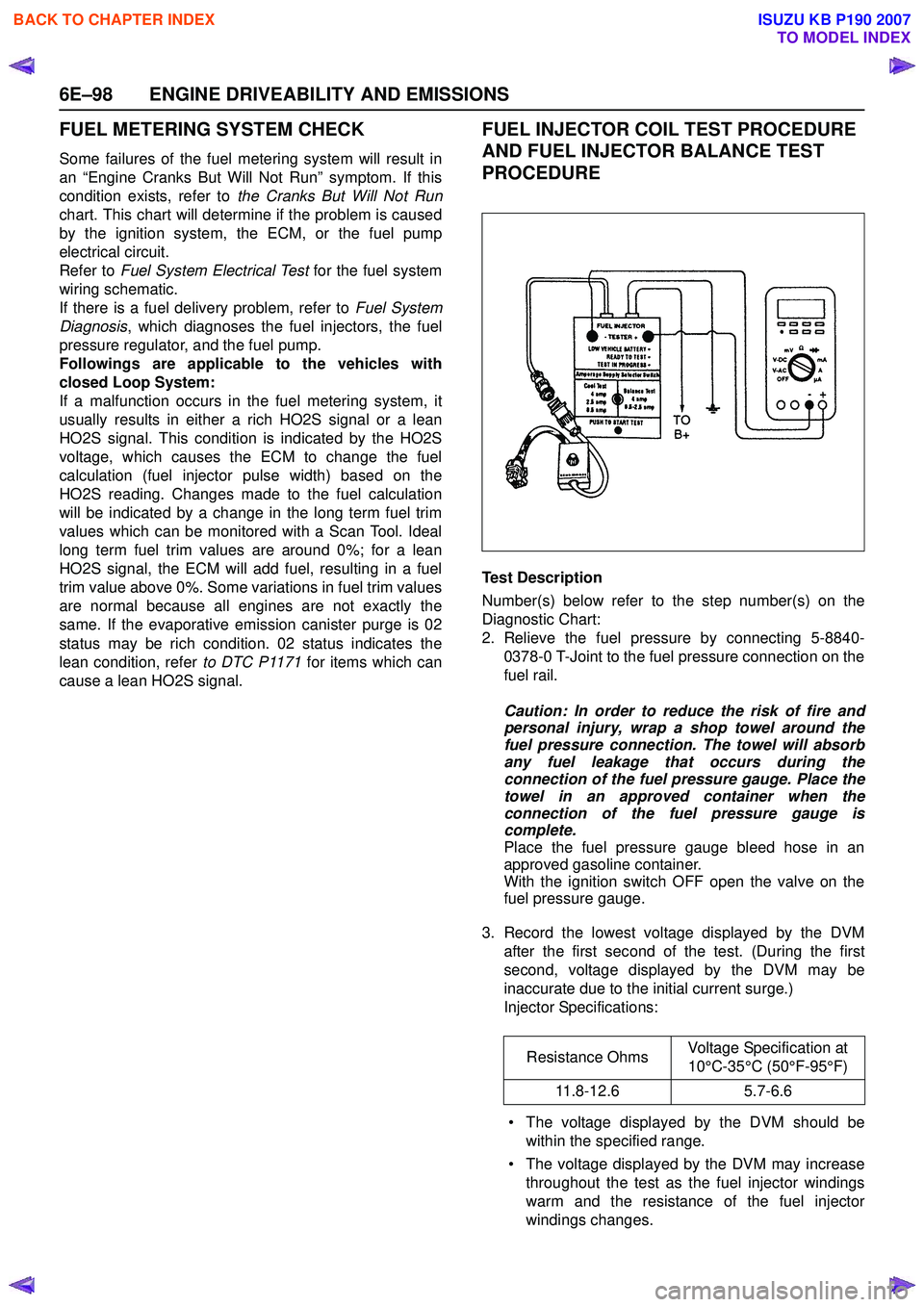
FUEL INJECTOR COIL TEST PROCEDURE
AND FUEL INJECTOR BALANCE TEST
PROCEDURE
Test Description
Number(s) below refer to the step number(s) on the
Diagnostic Chart:
2. Relieve the fuel pressure by connecting 5-8840- 0378-0 T-Joint to the fuel pressure connection on the
fuel rail.
Caution: In order to reduce the risk of fire and
personal injury, wrap a shop towel around the
fuel pressure connection. The towel will absorb
any fuel leakage that occurs during the
connection of the fuel pressure gauge. Place the
towel in an approved container when the
connection of the fuel pressure gauge is
complete.
Place the fuel pressure gauge bleed hose in an
approved gasoline container.
With the ignition switch OFF open the valve on the
fuel pressure gauge.
3. Record the lowest voltage displayed by the DVM after the first second of the test. (During the first
second, voltage displayed by the DVM may be
inaccurate due to the initial current surge.)
Injector Specifications:
• The voltage displayed by the DVM should be within the specified range.
• The voltage displayed by the DVM may increase throughout the test as the fuel injector windings
warm and the resistance of the fuel injector
windings changes. Resistance Ohms
Voltage Specification at
10°C-35°C (50°F-95°F)
11.8-12.6 5.7-6.6
BACK TO CHAPTER INDEX
TO MODEL INDEX
ISUZU KB P190 2007
Page 2279 of 6020
ENGINE DRIVEABILITY AND EMISSIONS 6E–109
• The fuel injector(s).
4. Fuel pressure that drops off during acceleration, cruise, or hard cornering may case a lean condition.
A lean condition can cause a loss of power, surging,
or misfire. A lean condition can be diagnosed using a
Tech 2 Scan Tool.
Following are applicable to the vehicle with
closed Loop System:
If an extremely lean condition occurs, the oxygen
sensor(s) will stop toggling. The oxygen sensor
output voltage(s) will drop below 500 mV. Also, the
fuel injector pulse width will increase.
Important: Make sure the fuel system is not
operating in the “Fuel Cut-Off Mode.”
When the engine is at idle, the manifold pressure is
low (high vacuum). This low pressure (high vacuum)
is applied to the fuel pressure regulator diaphragm.
The low pressure (high vacuum) will offset the
pressure being applied to the fuel pressure regulator
diaphragm by the spring inside the fuel pressure
regulator. When this happens, the result is lower fuel
pressure. The fuel pressure at idle will vary slightly
as the barometric pressure changes, but the fuel
pressure at idle should always be less than the fuel
pressure noted in step 2 with the engine OFF.
16.Check the spark plug associated with a particular
fuel injector for fouling or saturation in order to
determine if that particular fuel injector is leaking. If
checking the spark plug associated with a particular
fuel injector for fouling or saturation does not
determine that a particular fuel injector is leaking,
use the following procedure:
• Remove the fuel rail, but leave the fuel lines and injectors connected to the fuel rail. Refer to Fuel
Rail Assembly in On-Vehicle Service .
• Lift the fuel rail just enough to leave the fuel injector nozzles in the fuel injector ports.
Caution: In order to reduce the risk of fire and
personal injury that may result from fuel
spraying on the engine, verify that the fuel rail is
positioned over the fuel injector ports and verify
that the fuel injector retaining clips are intact.
• Pressurize the fuel system by connecting a 20 amp fused jumper between B+ and the fuel
pump relay connector.
• Visually and physically inspect the fuel injector nozzles for leaks.
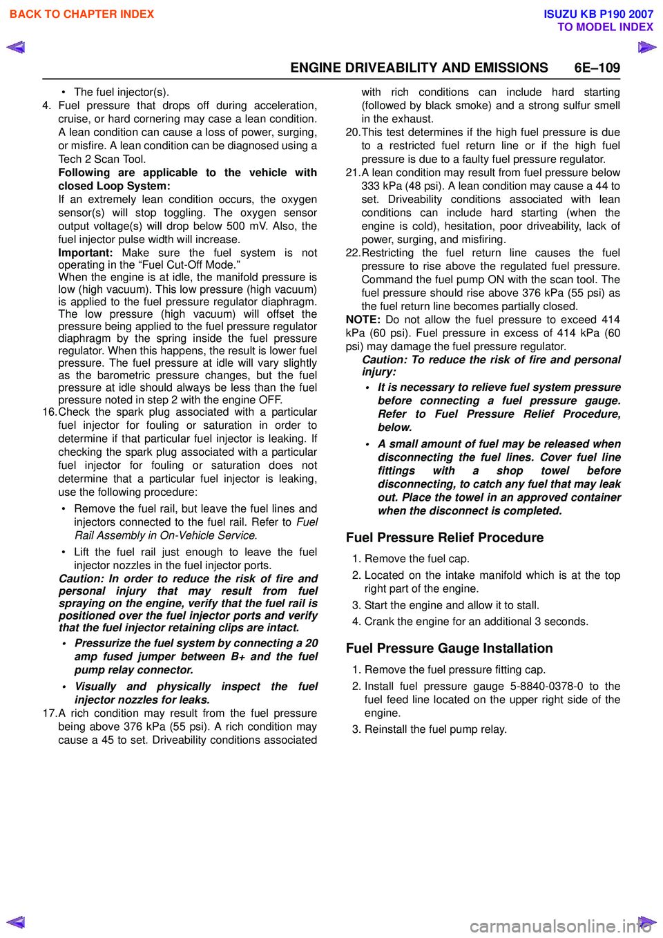
17.A rich condition may result from the fuel pressure being above 376 kPa (55 psi). A rich condition may
cause a 45 to set. Driveability conditions associated with rich conditions can include hard starting
(followed by black smoke) and a strong sulfur smell
in the exhaust.
20.This test determines if the high fuel pressure is due to a restricted fuel return line or if the high fuel
pressure is due to a faulty fuel pressure regulator.
21.A lean condition may result from fuel pressure below 333 kPa (48 psi). A lean condition may cause a 44 to
set. Driveability conditions associated with lean
conditions can include hard starting (when the
engine is cold), hesitation, poor driveability, lack of
power, surging, and misfiring.
22.Restricting the fuel return line causes the fuel pressure to rise above the regulated fuel pressure.
Command the fuel pump ON with the scan tool. The
fuel pressure should rise above 376 kPa (55 psi) as
the fuel return line becomes partially closed.
NOTE: Do not allow the fuel pressure to exceed 414
kPa (60 psi). Fuel pressure in excess of 414 kPa (60
psi) may damage the fuel pressure regulator. Caution: To reduce the risk of fire and personal
injury:
• It is necessary to relieve fuel system pressure before connecting a fuel pressure gauge.
Refer to Fuel Pressure Relief Procedure,
below.
• A small amount of fuel may be released when disconnecting the fuel lines. Cover fuel line
fittings with a shop towel before
disconnecting, to catch any fuel that may leak
out. Place the towel in an approved container
when the disconnect is completed.
Fuel Pressure Relief Procedure
1. Remove the fuel cap.
2. Located on the intake manifold which is at the top right part of the engine.
3. Start the engine and allow it to stall.
4. Crank the engine for an additional 3 seconds.
Fuel Pressure Gauge Installation
1. Remove the fuel pressure fitting cap.
2. Install fuel pressure gauge 5-8840-0378-0 to the fuel feed line located on the upper right side of the
engine.
3. Reinstall the fuel pump relay.
BACK TO CHAPTER INDEX
TO MODEL INDEX
ISUZU KB P190 2007