2007 ISUZU KB P190 width
[x] Cancel search: widthPage 2768 of 6020
Engine Mechanical – V6 Page 6A1–289
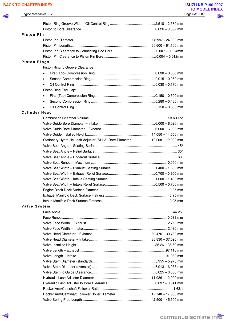
Piston Ring Groove Width - Oil Control Ring ............................................... 2.510 – 2.530 mm
Piston to Bore Clearance ............................................................................. 0.026 – 0.052 mm
Piston Pin
Piston Pin Diameter ..................................................................................23.997 - 24.000 mm
Piston Pin Length..................................................................................... 60.600 – 61.100 mm
Piston Pin Clearance to Connecting Rod Bore ............................................. 0.007 – 0.024mm
Piston Pin Clearance to Piston Pin Bore....................................................... 0.004 – 0.012mm
Piston Rings
Piston Ring to Groove Clearance:
• First (Top) Compression Ring............................................................... 0.030 – 0.065 mm
• Second Compression Ring ................................................................... 0.015 – 0.060 mm
• Oil Control Ring .................................................................................... 0.030 – 0.170 mm
Piston Ring End Gap:
• First (Top) Compression Ring............................................................... 0.150 – 0.300 mm
• Second Compression Ring ................................................................... 0.280 – 0.480 mm
• Oil Control Ring .................................................................................... 0.150 – 0.600 mm
Cylinder Head
Combustion Chamber Volume.................................................................................. 53.600 cc
Valve Guide Bore Diameter – Intake ........................................................... 6.000 – 6.020 mm
Valve Guide Bore Diameter – Exhaust ........................................................ 6.000 – 6.020 mm
Valve Guide Installed Height.................................................................... 14.050 – 14.550 mm
Stationary Hydraulic Lash Adjuster (SHLA) Bore Diameter ..................... 12.008 – 12.030 mm
Valve Seat Angle – Seating Surface ................................................................................... 45 °
Valve Seat Angle – Relief Surface ...................................................................................... 30 °
Valve Seat Angle – Undercut Surface ................................................................................ 60 °
Valve Seat Runout – Maximum ................................................................................ 0.050 mm
Valve Seat Width – Exhaust Seating Surface .............................................. 1.400 – 1.800 mm
Valve Seat Width – Exhaust Relief Surface ................................................. 0.700 – 0.900 mm
Valve Seat Width – Intake Seating Surface ................................................. 1.000 – 1.400 mm
Valve Seat Width – Intake Relief Surface .................................................... 0.500 – 0.700 mm
Engine Block Deck Surface Flatness .......................................................................... 0.05 mm
Exhaust Manifold Deck Surface Flatness ................................................................... 0.25 mm
Intake Manifold Deck Surface Flatness ...................................................................... 0.05 mm
Valve System
Face Angle..................................................................................................................... 44.25°
Face Runout ............................................................................................................. 0.038 m m
Valve Face Width – Exhaust..................................................................................... 2.750 mm
Valve Face Width – Intake ........................................................................................ 2.180 mm
Valve Head Diameter – Exhaust .............................................................. 30.470 – 30.730 mm
Valve Head Diameter – Intake ................................................................. 36.830 – 37.090 mm
Valve Installed Height .................................................................................. 35.26 – 36.69 mm
Valve Length – Exhaust .......................................................................................... 97.110 mm
Valve Length – Intake ........................................................................................... 101.230 mm
Valve Stem Diameter (standard).................................................................. 5.955 – 5.975 mm
Valve Stem Diameter (oversize) .................................................................. 6.013 – 6.033 mm
Valve Stem to Guide Clearance................................................................... 0.025 – 0.065 mm
Hydraulic Lash Adjuster Diameter ........................................................... 11.986 – 12.000 mm
Hydraulic Lash Adjuster to Bore Clearance ................................................. 0.037 – 0.041 mm
Rocker Arm/Camshaft Follower Ratio............................................................................. 1.68:1
Rocker Arm/Camshaft Follower Roller Diameter ..................................... 17.740 – 17.800 mm
Valve Spring Free Length ........................................................................ 42.500 – 45.500 mm
BACK TO CHAPTER INDEX
TO MODEL INDEX
ISUZU KB P190 2007
Page 2832 of 6020
Engine Mechanical – V6 Page 6A1–55
Page 6A1–55
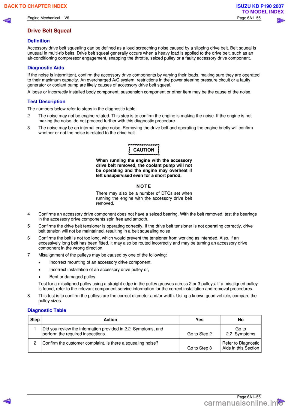
Drive Belt Squeal
Definition
Accessory drive belt squealing can be defined as a loud screeching noise caused by a slipping drive belt. Belt squeal is
unusual in multi-rib belts. Drive belt squeal generally occurs when a heavy load is applied to the drive belt, such as an
air-conditioning compressor engagement, snapping the throttle, se ized pulley or a faulty accessory drive component.
Diagnostic Aids
If the noise is intermittent, confirm the accessory drive components by varying t heir loads, making sure they are operated
to their maximum capacity. An overcharged A/C system, restrictions in the power steering pressure circuit or a faulty
generator or coolant pump are likely c auses of accessory drive belt squeal.
A loose or incorrectly installed body component, suspension component or other item may be the cause of the noise.
Test Description
The numbers below refer to steps in the diagnostic table.
2 The noise may not be engine related. This step is to confirm the engine is making t he noise. If the engine is not
making the noise, do not proceed further with this diagnostic procedure.
3 The noise may be an internal engine noise. Removing the drive belt and operating the engine briefly will confirm
whether or not the noise is related to the drive belt.
CAUTION
When running the engine with the accessory
drive belt removed, the coolant pump will not
be operating and the engine may overheat if
left unsupervised even for a short period.
NOTE
There may also be a number of DTCs set when
running the engine with the accessory drive belt
removed.
4 Confirms an accessory drive component does not have a se ized bearing. With the belt removed, test the bearings
in the accessory drive co mponents spin free and smooth.
5 Confirms the drive belt tensioner is operating correctly. If the drive belt tensioner is not operating correctly, drive
belt tension will not be maintained, resulting in a belt squealing noise
6 Confirms the belt is not too long, which would prevent the tensioner from working as intended. Also, if an
excessively long belt has been fitted, it may also be r outed incorrectly and may be turning an accessory drive
component in the wrong direction.
7 Misalignment of the pulleys may be caused by one of the following:
• Incorrect mounting of an accessory drive component,
• Incorrect installation of an accessory drive pulley or,
• Bent or damaged pulley.
Test for a misaligned pulley using a straight edge in the pulley grooves across 2 or 3 pulleys. If a misaligned pulley is found, refer to the relevant component service info rmation for the correct installation and removal procedures.
8 This test is to confirm the pulleys are the correct di ameter and/or width. Using a known good vehicle, compare the
pulley sizes.
Diagnostic Table
Step Action Yes No
1
Did you review the information provided in 2.2 Symptoms, and
perform the required inspections. Go to Step 2 Go to
2.2 Symptoms
2 Confirm the customer compla int. Is there a squealing noise?
Go to Step 3 Refer to Diagnostic
Aids in this Section
BACK TO CHAPTER INDEX
TO MODEL INDEX
ISUZU KB P190 2007
Page 2841 of 6020
Engine Mechanical – V6 Page 6A1–64
Page 6A1–64
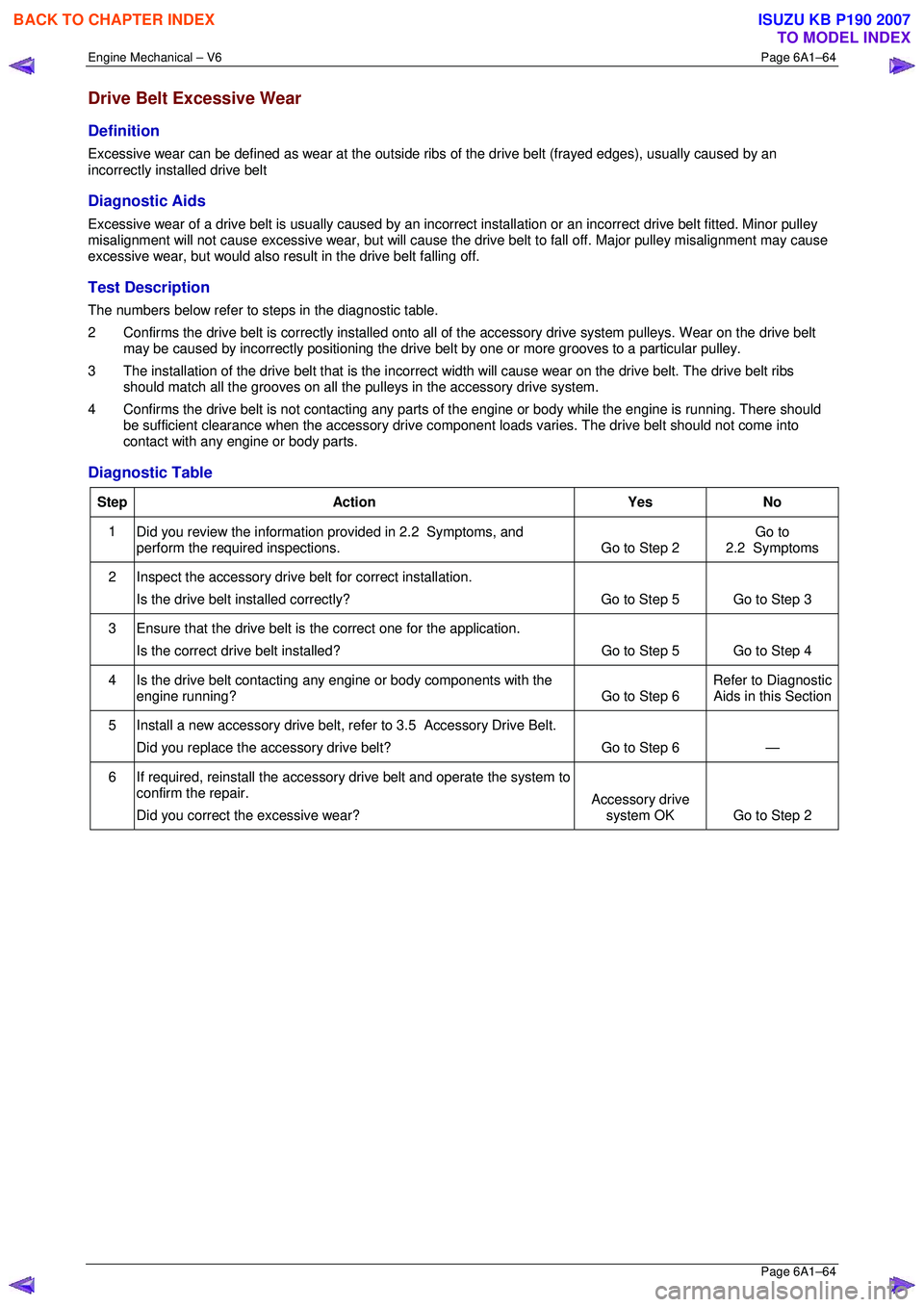
Drive Belt Excessive Wear
Definition
Excessive wear can be defined as wear at the outside ribs of the drive belt (frayed edges), usually caused by an
incorrectly installed drive belt
Diagnostic Aids
Excessive wear of a drive belt is usually caused by an incorre ct installation or an incorrect drive belt fitted. Minor pulley
misalignment will not cause excessive wear, but will cause the drive belt to fall off. Major pulley misalignment may cause
excessive wear, but would also re sult in the drive belt falling off.
Test Description
The numbers below refer to steps in the diagnostic table.
2 Confirms the drive belt is correctly installed onto all of the accessory drive system pulleys. Wear on the drive belt
may be caused by incorrectly positioning the drive belt by one or more grooves to a particular pulley.
3 The installation of the drive belt that is the incorrect width will cause wear on the drive belt. The drive belt ribs
should match all the grooves on all the pu lleys in the accessory drive system.
4 Confirms the drive belt is not cont acting any parts of the engine or body wh ile the engine is running. There should
be sufficient clearance when the accessory drive component loads varies. The drive belt should not come into
contact with any engine or body parts.
Diagnostic Table
Step Action Yes No
1
Did you review the information provided in 2.2 Symptoms, and
perform the required inspections. Go to Step 2 Go to
2.2 Symptoms
2 Inspect the accessory drive belt for correct installation.
Is the drive belt installed correctly? Go to Step 5 Go to Step 3
3 Ensure that the drive belt is
the correct one for the application.
Is the correct drive belt installed? Go to Step 5 Go to Step 4
4 Is the drive belt contacting any engine or body components with the
engine running? Go to Step 6 Refer to Diagnostic
Aids in this Section
5 Install a new accessory drive belt, re fer to 3.5 Accessory Drive Belt.
Did you replace the accessory drive belt? Go to Step 6 —
6 If required, reinstall the accessory drive belt and operate the system to
confirm the repair.
Did you correct the excessive wear? Accessory drive
system OK Go to Step 2
BACK TO CHAPTER INDEX
TO MODEL INDEX
ISUZU KB P190 2007
Page 2983 of 6020
Engine Mechanical – V6 Page 6A1–206
Page 6A1–206
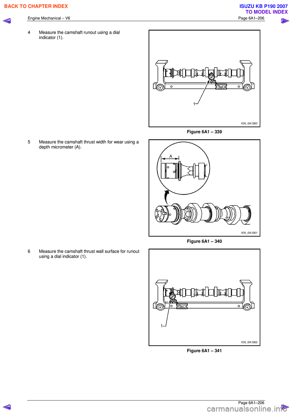
4 Measure the camshaft runout using a dial
indicator (1).
Figure 6A1 – 339
5 Measure the camshaft thrust width for wear using a depth micrometer (A).
Figure 6A1 – 340
6 Measure the camshaft thrust wall surface for runout using a dial indicator (1).
Figure 6A1 – 341
BACK TO CHAPTER INDEX
TO MODEL INDEX
ISUZU KB P190 2007
Page 2991 of 6020
Engine Mechanical – V6 Page 6A1–214
Page 6A1–214
Reinstall
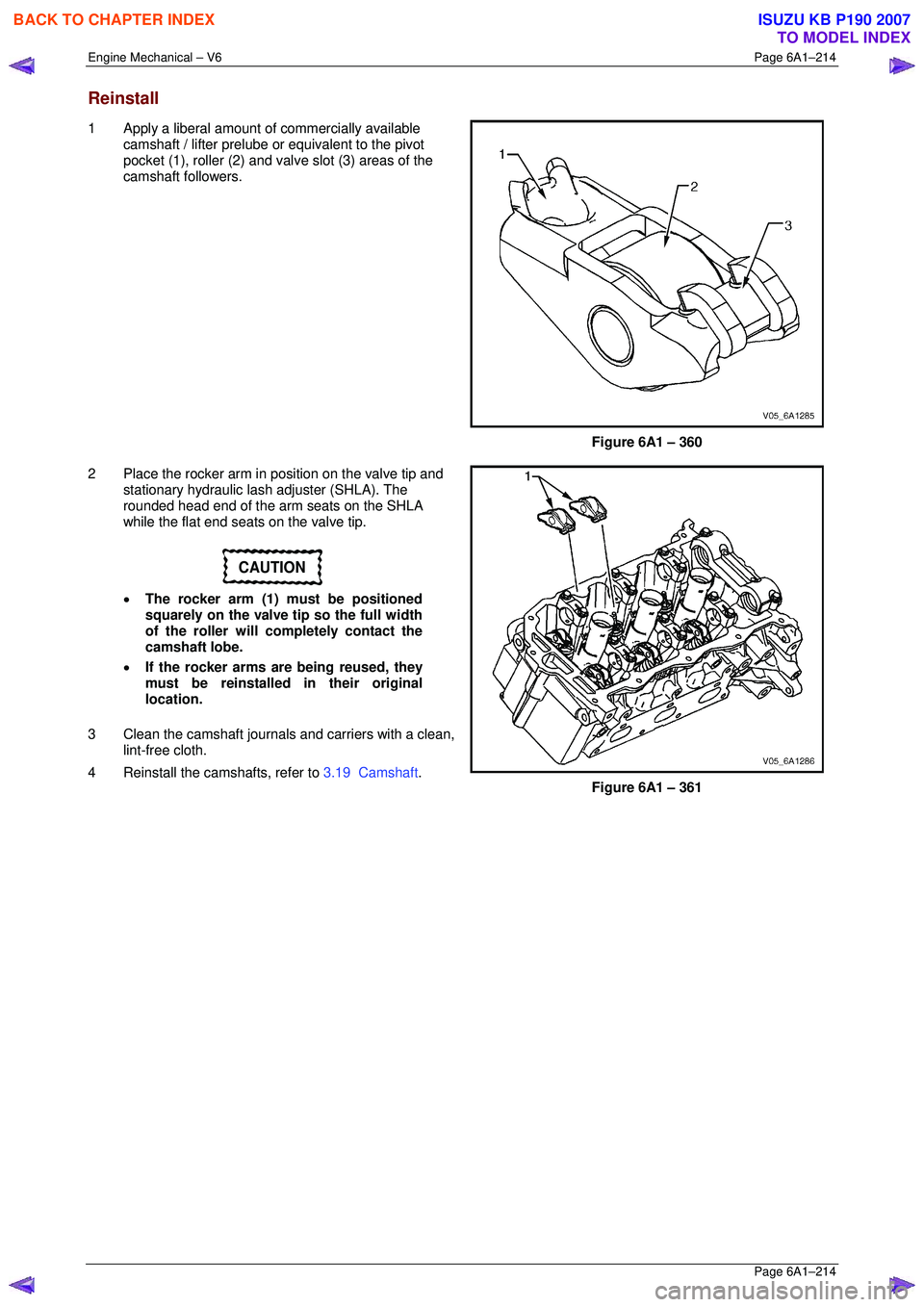
1 Apply a liberal amount of commercially available
camshaft / lifter prelube or equivalent to the pivot
pocket (1), roller (2) and valve slot (3) areas of the
camshaft followers.
Figure 6A1 – 360
2 Place the rocker arm in position on the valve tip and stationary hydraulic lash adjuster (SHLA). The
rounded head end of the arm seats on the SHLA
while the flat end seats on the valve tip.
CAUTION
• The rocker arm (1) must be positioned
squarely on the valve tip so the full width
of the roller will completely contact the
camshaft lobe.
• If the rocker arms are being reused, they
must be reinstalled in their original
location.
3 Clean the camshaft journals and carriers with a clean, lint-free cloth.
4 Reinstall the camshafts, refer to 3.19 Camshaft.
Figure 6A1 – 361
BACK TO CHAPTER INDEX
TO MODEL INDEX
ISUZU KB P190 2007
Page 3003 of 6020
Engine Mechanical – V6 Page 6A1–226
Page 6A1–226
Valve Visual Inspection Procedure
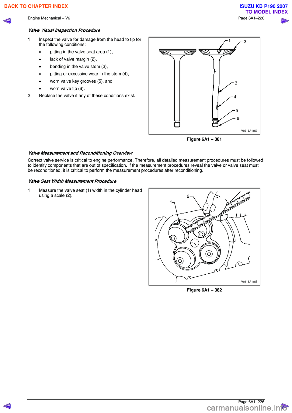
1 Inspect the valve for damage from the head to tip for
the following conditions:
• pitting in the valve seat area (1),
• lack of valve margin (2),
• bending in the valve stem (3),
• pitting or excessive wear in the stem (4),
• worn valve key grooves (5), and
• worn valve tip (6).
2 Replace the valve if any of these conditions exist.
Figure 6A1 – 381
Valve Measurement and Reconditioning Overview
Correct valve service is critical to engine performance. Therefore, all detailed measurement procedures must be followed
to identify components that are out of specification. If the measurement procedures reveal t he valve or valve seat must
be reconditioned, it is critical to perform t he measurement procedures after reconditioning.
Valve Seat Width Measurement Procedure
1 Measure the valve seat (1) width in the cylinder head
using a scale (2).
Figure 6A1 – 382
BACK TO CHAPTER INDEX
TO MODEL INDEX
ISUZU KB P190 2007
Page 3004 of 6020
Engine Mechanical – V6 Page 6A1–227
Page 6A1–227
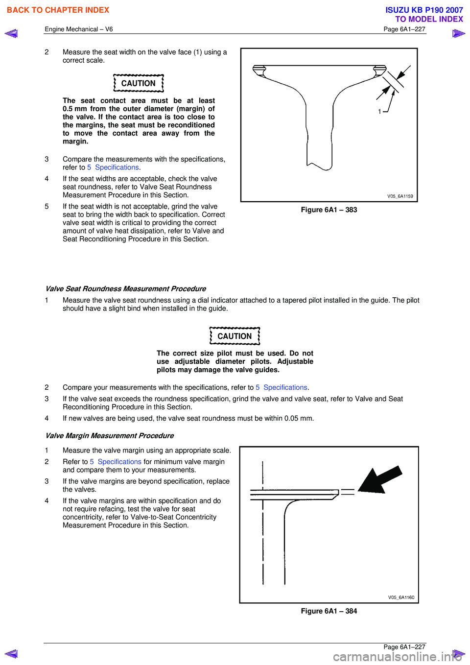
2 Measure the seat width on the valve face (1) using a
correct scale.
CAUTION
The seat contact area must be at least
0.5 mm from the outer diameter (margin) of
the valve. If the contact area is too close to
the margins, the seat must be reconditioned
to move the contact area away from the
margin.
3 Compare the measurements with the specifications,
refer to 5 Specifications .
4 If the seat widths are a cceptable, check the valve
seat roundness, refer to Valve Seat Roundness
Measurement Procedure in this Section.
5 If the seat width is not acceptable, grind the valve
seat to bring the width back to specification. Correct
valve seat width is critical to providing the correct
amount of valve heat dissipat ion, refer to Valve and
Seat Reconditioning Procedure in this Section.
Figure 6A1 – 383
Valve Seat Roundness Measurement Procedure
1 Measure the valve seat roundness using a dial indicator a ttached to a tapered pilot installed in the guide. The pilot
should have a slight bind w hen installed in the guide.
CAUTION
The correct size pilot must be used. Do not
use adjustable diameter pilots. Adjustable
pilots may damage the valve guides.
2 Compare your measurements with the specifications, refer to 5 Specifications.
3 If the valve seat exceeds the roundne ss specification, grind the valve and valve seat, refer to Valve and Seat
Reconditioning Procedure in this Section.
4 If new valves are being used, the valv e seat roundness must be within 0.05 mm.
Valve Margin Measurement Procedure
1 Measure the valve margin using an appropriate scale.
2 Refer to 5 Specifications for minimum valve margin
and compare them to your measurements.
3 If the valve margins are beyond specification, replace the valves.
4 If the valve margins are within specification and do not require refacing, test the valve for seat
concentricity, refer to Valve-to-Seat Concentricity
Measurement Procedure in this Section.
Figure 6A1 – 384
BACK TO CHAPTER INDEX
TO MODEL INDEX
ISUZU KB P190 2007
Page 3005 of 6020
Engine Mechanical – V6 Page 6A1–228
Page 6A1–228
Valve-to-Seat Concentricity Measurement Procedure
Checking the valve-to-seat concentricity determines whether the valve and seat are sealing correctly.
Measure the valve face and the valve s eat to ensure correct valve sealing.
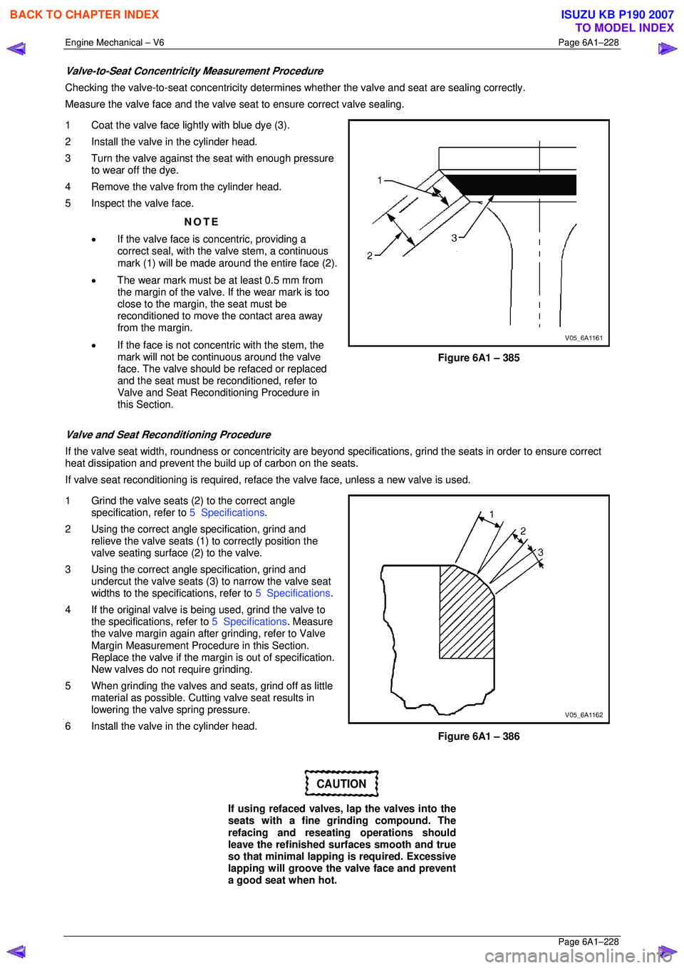
1 Coat the valve face lightly with blue dye (3).
2 Install the valve in the cylinder head.
3 Turn the valve against the seat with enough pressure to wear off the dye.
4 Remove the valve from the cylinder head.
5 Inspect the valve face.
NOTE
• If the valve face is concentric, providing a
correct seal, with the valve stem, a continuous
mark (1) will be made around the entire face (2).
• The wear mark must be at least 0.5 mm from
the margin of the valve. If the wear mark is too
close to the margin, the seat must be
reconditioned to move the contact area away
from the margin.
• If the face is not concentric with the stem, the
mark will not be continuous around the valve
face. The valve should be refaced or replaced
and the seat must be reconditioned, refer to
Valve and Seat Reconditioning Procedure in
this Section.
Figure 6A1 – 385
Valve and Seat Reconditioning Procedure
If the valve seat width, roundness or conc entricity are beyond specifications, grind the seats in order to ensure correct
heat dissipation and prevent the bu ild up of carbon on the seats.
If valve seat reconditioning is required, reface the valve face, unless a new valve is used.
1 Grind the valve seats (2) to the correct angle specification, refer to 5 Specifications.
2 Using the correct angle specification, grind and
relieve the valve seats (1) to correctly position the
valve seating surface (2) to the valve.
3 Using the correct angle specification, grind and
undercut the valve seats (3) to narrow the valve seat
widths to the specifications, refer to 5 Specifications.
4 If the original valve is being used, grind the valve to the specifications, refer to 5 Specifications. Measure
the valve margin again after grinding, refer to Valve
Margin Measurement Procedure in this Section.
Replace the valve if the margin is out of specification.
New valves do not require grinding.
5 When grinding the valves and seats, grind off as little material as possible. Cutti ng valve seat results in
lowering the valve spring pressure.
6 Install the valve in the cylinder head.
Figure 6A1 – 386
CAUTION
If using refaced valves, lap the valves into the
seats with a fine grinding compound. The
refacing and reseati ng operations should
leave the refinished surfaces smooth and true
so that minimal lapping is required. Excessive
lapping will groove the valve face and prevent
a good seat when hot.
BACK TO CHAPTER INDEX
TO MODEL INDEX
ISUZU KB P190 2007