2007 ISUZU KB P190 width
[x] Cancel search: widthPage 1984 of 6020
ENGINE CONTROL SYSTEM (4JK1/4JJ1) 6E-367
The amount of air pressure rise and air volume
delivered to the engine from the compressor outlet is
regulated by a waste gate valve in the exhaust housing.
The position of the waste gate valve is controlled by the
amount of pressure built up on the intake side of the
turbocharger. The diaphragm on the inside of the waste
gate is pressure sensitive, and controls the position of
the valve inside the turbocharger. The position of the
valve will increase or decrease the amount of boost to
the turbocharger. (Standard output engine)
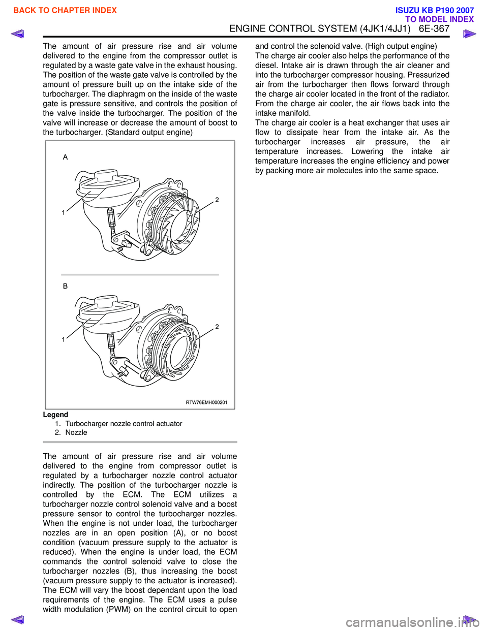
Legend
1. Turbocharger nozzle control actuator
2. Nozzle
The amount of air pressure rise and air volume
delivered to the engine from compressor outlet is
regulated by a turbocharger nozzle control actuator
indirectly. The position of the turbocharger nozzle is
controlled by the ECM. The ECM utilizes a
turbocharger nozzle control solenoid valve and a boost
pressure sensor to control the turbocharger nozzles.
When the engine is not under load, the turbocharger
nozzles are in an open position (A), or no boost
condition (vacuum pressure supply to the actuator is
reduced). When the engine is under load, the ECM
commands the control solenoid valve to close the
turbocharger nozzles (B), thus increasing the boost
(vacuum pressure supply to the actuator is increased).
The ECM will vary the boost dependant upon the load
requirements of the engine. The ECM uses a pulse
width modulation (PWM) on the control circuit to open and control the solenoid valve. (High output engine)
The charge air cooler also helps the performance of the
diesel. Intake air is drawn through the air cleaner and
into the turbocharger compressor housing. Pressurized
air from the turbocharger then flows forward through
the charge air cooler located in the front of the radiator.
From the charge air cooler, the air flows back into the
intake manifold.
The charge air cooler is a heat exchanger that uses air
flow to dissipate hear from the intake air. As the
turbocharger increases air pressure, the air
temperature increases. Lowering the intake air
temperature increases the engine efficiency and power
by packing more air molecules into the same space.
RTW76EMH000201
A
B
1
2
1
2
BACK TO CHAPTER INDEX
TO MODEL INDEX
ISUZU KB P190 2007
Page 2053 of 6020

ENGINE MECHANICAL (C24SE) 6A-39
Camshaft Housing, Check for Plane Surface
Clean
Sealing surfaces.
Inspection
Check length and width of sealing surface for deformation and
diagnosis for warpage and use straight edge feeler gauge.
Measure
Height of camshaft housing (sealing surface to sealing
surface).
Dimension I: (74.0 mm)
Cylinder Head, Removal and Installation
Important
Only remove cylinder head with engine cold (room
temperature).
Removal
1. Remove the alternator, power steering and V-belts.
Removal
2. Loosen the fastening bolts from alternator.
3. Loosen the lower alternator fastening bolt by swinging the alternator to the rear.
Removal
4. Remove the front toothed belt cover.
5. Remove the toothed belt from camshaft pulley.
See operation "Timing Check and Adjust".
BACK TO CHAPTER INDEX
TO MODEL INDEX
ISUZU KB P190 2007
Page 2059 of 6020
ENGINE MECHANICAL (C24SE) 6A-45
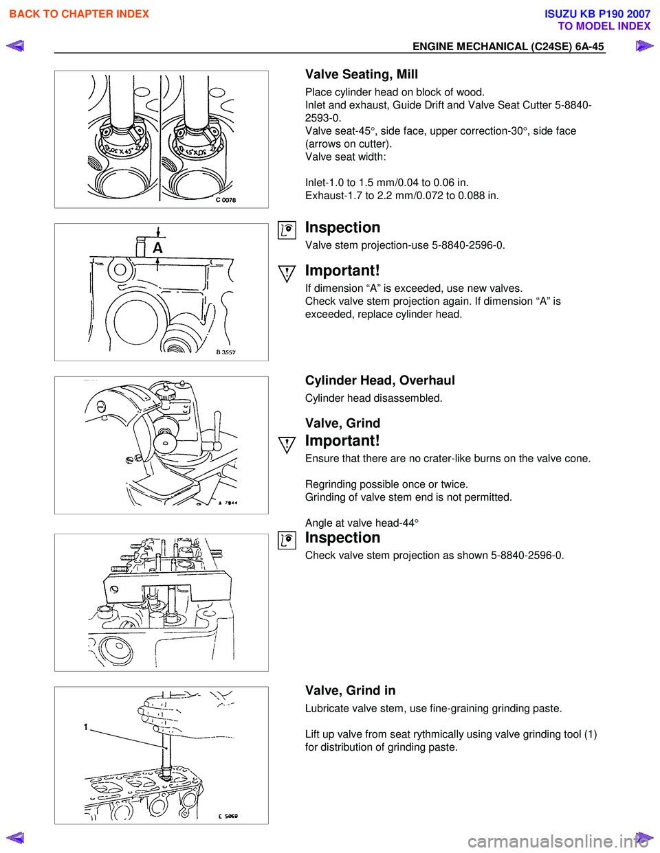
Valve Seating, Mill
Place cylinder head on block of wood.
Inlet and exhaust, Guide Drift and Valve Seat Cutter 5-8840-
2593-0.
Valve seat-45 °, side face, upper correction-30 °, side face
(arrows on cutter).
Valve seat width:
Inlet-1.0 to 1.5 mm/0.04 to 0.06 in.
Exhaust-1.7 to 2.2 mm/0.072 to 0.088 in.
Inspection
Valve stem projection-use 5-8840-2596-0.
Important!
If dimension “A” is exceeded, use new valves.
Check valve stem projection again. If dimension “A” is
exceeded, replace cylinder head.
Cylinder Head, Overhaul
Cylinder head disassembled.
Valve, Grind
Important!
Ensure that there are no crater-like burns on the valve cone.
Regrinding possible once or twice.
Grinding of valve stem end is not permitted.
Angle at valve head-44 °
Inspection
Check valve stem projection as shown 5-8840-2596-0.
Valve, Grind in
Lubricate valve stem, use fine-graining grinding paste.
Lift up valve from seat rythmically using valve grinding tool (1)
for distribution of grinding paste.
BACK TO CHAPTER INDEX
TO MODEL INDEX
ISUZU KB P190 2007
Page 2070 of 6020
6A-56 ENGINE MECHANICAL (C24SE)
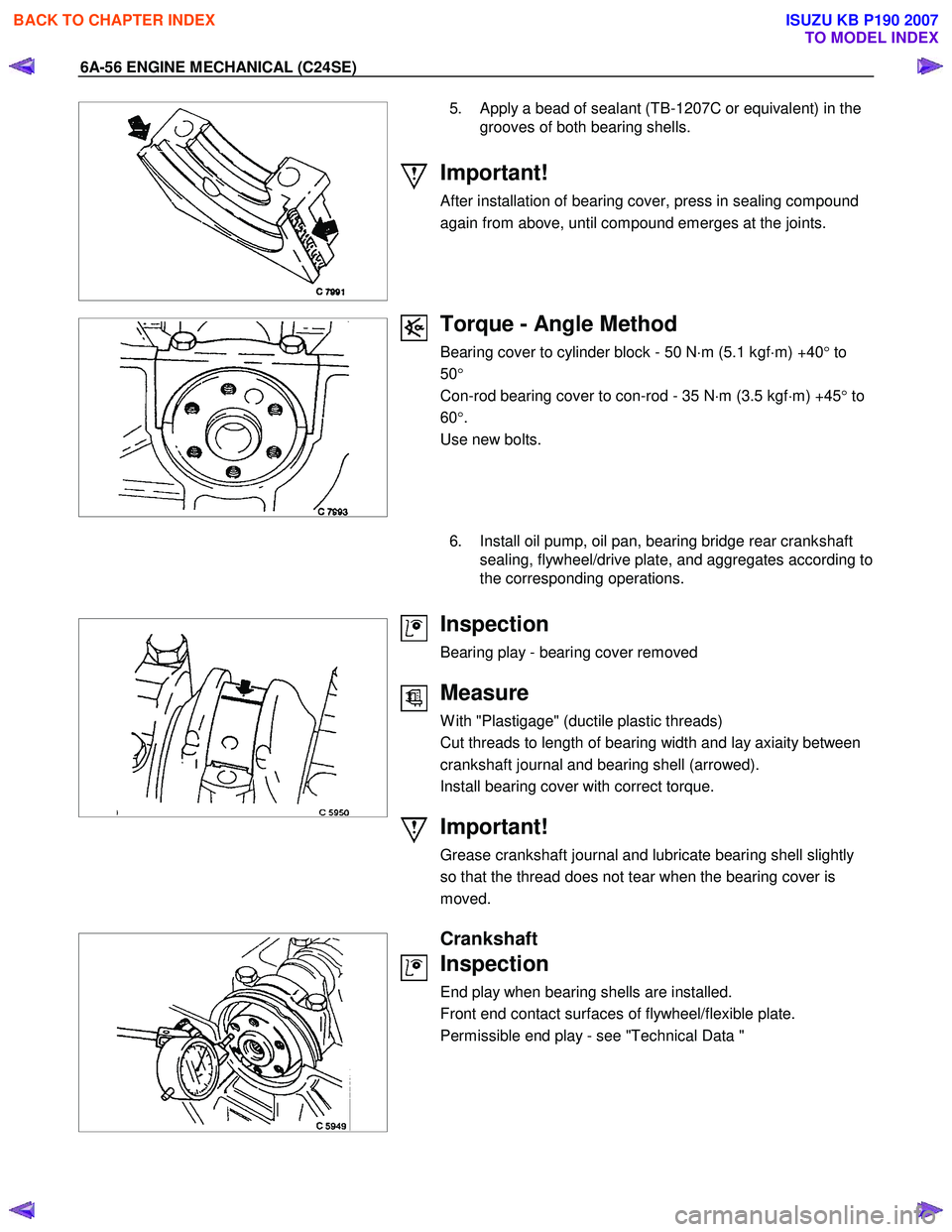
5. Apply a bead of sealant (TB-1207C or equivalent) in the grooves of both bearing shells.
Important!
After installation of bearing cover, press in sealing compound
again from above, until compound emerges at the joints.
Torque - Angle Method
Bearing cover to cylinder block - 50 N ⋅m (5.1 kgf ⋅m) +40 ° to
50 °
Con-rod bearing cover to con-rod - 35 N ⋅m (3.5 kgf ⋅m) +45 ° to
60 °.
Use new bolts.
6. Install oil pump, oil pan, bearing bridge rear crankshaft
sealing, flywheel/drive plate, and aggregates according to
the corresponding operations.
Inspection
Bearing play - bearing cover removed
Measure
W ith "Plastigage" (ductile plastic threads)
Cut threads to length of bearing width and lay axiaity between
crankshaft journal and bearing shell (arrowed).
Install bearing cover with correct torque.
Important!
Grease crankshaft journal and lubricate bearing shell slightly
so that the thread does not tear when the bearing cover is
moved.
Crankshaft
Inspection
End play when bearing shells are installed.
Front end contact surfaces of flywheel/flexible plate.
Permissible end play - see "Technical Data "
BACK TO CHAPTER INDEX
TO MODEL INDEX
ISUZU KB P190 2007
Page 2071 of 6020
ENGINE MECHANICAL (C24SE) 6A-57
Inspection
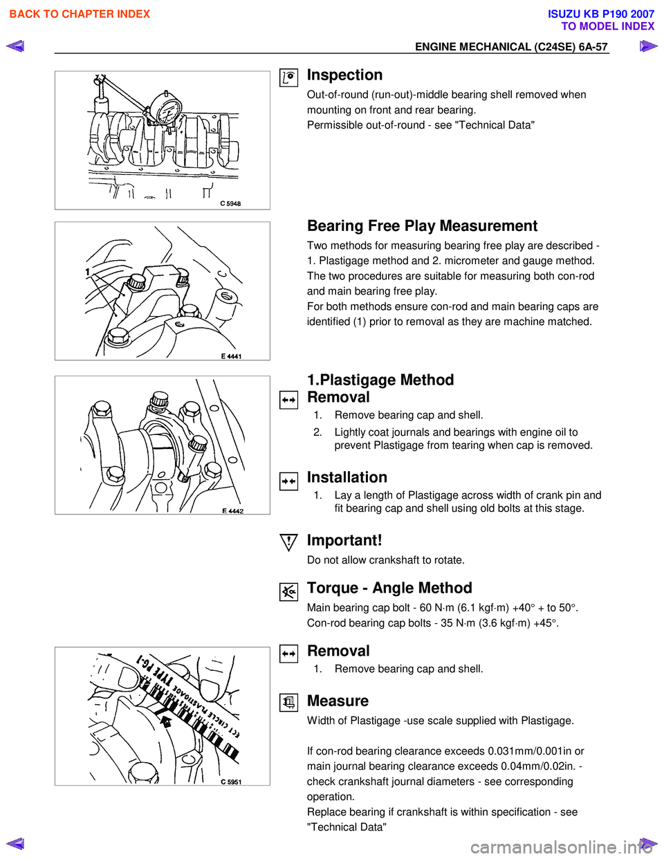
Out-of-round (run-out)-middle bearing shell removed when
mounting on front and rear bearing.
Permissible out-of-round - see "Technical Data"
Bearing Free Play Measurement
Two methods for measuring bearing free play are described -
1. Plastigage method and 2. micrometer and gauge method.
The two procedures are suitable for measuring both con-rod
and main bearing free play.
For both methods ensure con-rod and main bearing caps are
identified (1) prior to removal as they are machine matched.
1.Plastigage Method
Removal
1. Remove bearing cap and shell.
2. Lightly coat journals and bearings with engine oil to prevent Plastigage from tearing when cap is removed.
Installation
1. Lay a length of Plastigage across width of crank pin and fit bearing cap and shell using old bolts at this stage.
Important!
Do not allow crankshaft to rotate.
Torque - Angle Method
Main bearing cap bolt - 60 N ⋅m (6.1 kgf ⋅m) +40 ° + to 50 °.
Con-rod bearing cap bolts - 35 N ⋅m (3.6 kgf ⋅m) +45 °.
Removal
1. Remove bearing cap and shell.
Measure
W idth of Plastigage -use scale supplied with Plastigage.
If con-rod bearing clearance exceeds 0.031mm/0.001in or
main journal bearing clearance exceeds 0.04mm/0.02in. -
check crankshaft journal diameters - see corresponding
operation.
Replace bearing if crankshaft is within specification - see
"Technical Data"
BACK TO CHAPTER INDEX
TO MODEL INDEX
ISUZU KB P190 2007
Page 2093 of 6020
ENGINE MECHANICAL (C24SE) 6A-79
Adjustment Values/Checking Values
Valve clearance Inlet Hydraulic valve lash adjustment
Outlet No adjustment necessary
Spark plugs - electrode gap 1.0 ∼ 1.1mm
Compression The difference in compression
between the individual cylinders
in the engine must not exceed
100 kPa (1 bar).
Pressure loss The pressure loss of an engine
in perfect condition per cylinder
is not more than max. 25%
Cylinder Head
Cylinder Head Gasket
Thickness - installed mm 1.2
Valve seat width at cylinder head
inlet mm 1.0 to 1.5
outlet mm 1.7 to 2.2
Valve stem play inlet mm 0.018 to 0.052
outlet mm 0.038 to 0.072
Permissible valve stem to cone runout
inlet mm 0.03
outlet mm 0.33
Overall height of cylinder head
(Sealing surface to sealing surface) mm 95.5 ± 0.25
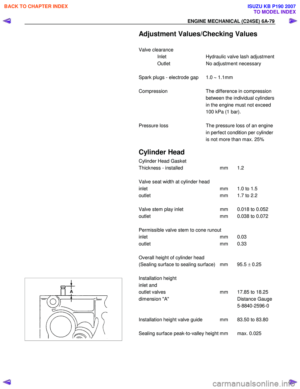
Installation height
inlet and
outlet valves mm 17.85 to 18.25
dimension "A" Distance Gauge
5-8840-2596-0
Installation height valve guide mm 83.50 to 83.80
Sealing surface peak-to-valley height mm max. 0.025
BACK TO CHAPTER INDEX
TO MODEL INDEX
ISUZU KB P190 2007
Page 2098 of 6020
6A-84 ENGINE MECHANICAL (C24SE)
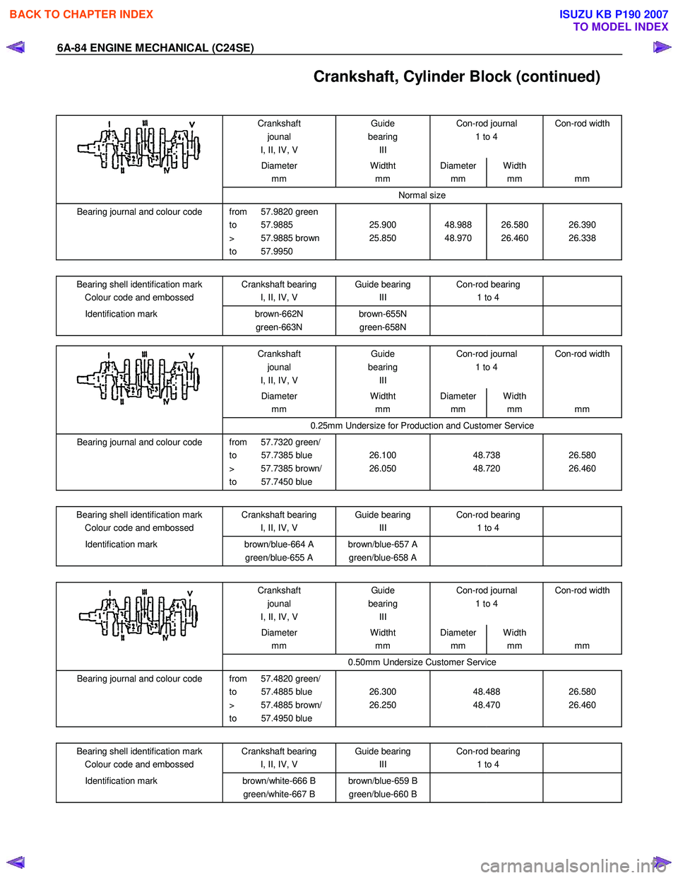
Crankshaft, Cylinder Block (continued)
Crankshaft jounal
I, II, IV, V Guide
bearing III Con-rod journal
1 to 4 Con-rod width
Diameter
mm Widtht
mm Diameter
mm Width
mm
mm
Normal size
Bearing journal and colour code from 57.9820 green
to 57.9885
> 57.9885 brown
to 57.9950
25.900
25.850
48.988
48.970
26.580
26.460
26.390
26.338
Bearing shell identification mark
Colour code and embossed Crankshaft bearing
I, II, IV, V Guide bearing
III Con-rod bearing
1 to 4
Identification mark
brown-662N
green-663N brown-655N
green-658N
Crankshaft
jounal
I, II, IV, V Guide
bearing III Con-rod journal
1 to 4 Con-rod width
Diameter
mm Widtht
mm Diameter
mm Width
mm
mm
0.25mm Undersize for Production and Customer Service
Bearing journal and colour code from 57.7320 green/
to 57.7385 blue
> 57.7385 brown/
to 57.7450 blue
26.100
26.050
48.738
48.720
26.580
26.460
Bearing shell identification mark Colour code and embossed Crankshaft bearing
I, II, IV, V Guide bearing
III Con-rod bearing
1 to 4
Identification mark
brown/blue-664 A
green/blue-655 A brown/blue-657 A
green/blue-658 A
Crankshaft jounal
I, II, IV, V Guide
bearing III Con-rod journal
1 to 4 Con-rod width
Diameter
mm Widtht
mm Diameter
mm Width
mm
mm
0.50mm Undersize Customer Service
Bearing journal and colour code from 57.4820 green/
to 57.4885 blue
> 57.4885 brown/
to 57.4950 blue
26.300
26.250
48.488
48.470
26.580
26.460
Bearing shell identification mark
Colour code and embossed Crankshaft bearing
I, II, IV, V Guide bearing
III Con-rod bearing
1 to 4
Identification mark
brown/white-666 B
green/white-667 B brown/blue-659 B
green/blue-660 B
BACK TO CHAPTER INDEX
TO MODEL INDEX
ISUZU KB P190 2007
Page 2100 of 6020
6A-86 ENGINE MECHANICAL (C24SE)
Con-rod
Permissible, weight variation of con-rods without pistons and bearing shells within an engine 8 g.
As the con-rods have no counterweights, re-working is not possible.
Con-rods must be replaced only as a set.
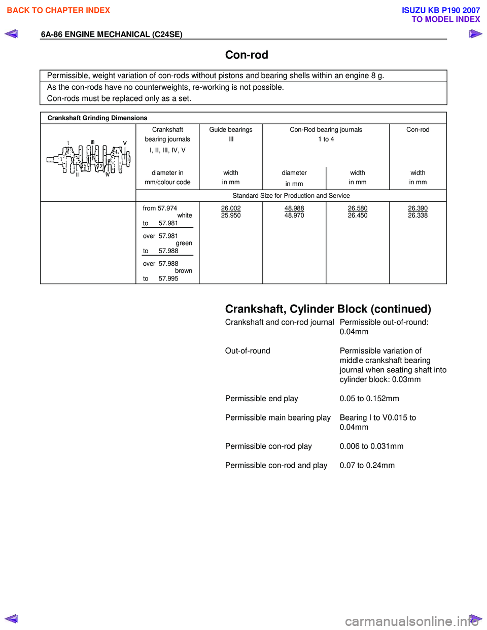
Crankshaft Grinding Dimensions
Crankshaft
bearing journals
I, II, III, IV, V Guide bearings
III
Con-Rod bearing journals
1 to 4
Con-rod
diameter
in
mm/colour code width
in mm diameter
in mm width
in mm width
in mm
Standard Size for Production and Service
from 57.974
white
to 57.981
over 57.981 green
to 57.988
over 57.988 brown
to 57.995 26.002
25.950
48.988
48.970
26.580
26.450
26.390
26.338
Crankshaft, Cylinder Block (continued)
Crankshaft and con-rod journal Permissible out-of-round:
0.04mm
Out-of-round Permissible variation of
middle crankshaft bearing
journal when seating shaft into
cylinder block: 0.03mm
Permissible end play 0.05 to 0.152mm
Permissible main bearing play Bearing I to V0.015 to 0.04mm
Permissible con-rod play 0.006 to 0.031mm
Permissible con-rod and play 0.07 to 0.24mm
BACK TO CHAPTER INDEX
TO MODEL INDEX
ISUZU KB P190 2007