2007 ISUZU KB P190 width
[x] Cancel search: widthPage 1445 of 6020

ENGINE MECHANICAL (4JK1/4JJ1) 6A-85
011RY00023
Valve Thickness
Measure the valve thickness.
If the measured value is less than the specified limit, the
valve and the valve guide must be replaced as a set.
Intake and Exhasut Valve Thickness mm (in)
Standard 1.32 (0.052)
Limit 1.1 (0.043)
014RY00020
Valve Depression
1. Install the valve (1) to the cylinder head (2).
2. Use a depth gauge or a straight edge with steel rule to measure the valve depression from the
cylinder head lower surface.
If the measured value exceeds the specified limit, the valve seat insert must be replaced.
Valve Depression mm (in)
Standard 1.8 (0.07)
Limit 2.5 (0.098)
014RY00021
Valve Contact Width
1. Check the valve contact faces for roughness and
unevenness. Make smooth the valve contact
surfaces.
2. Measure the valve contact width.
If the measured value exceeds the specified limit, the valve seat insert must be replaced.
Valve Contact W idth
mm (in)
Intake Exhaust
Standard 1.7 (0.067) 2.0 (0.079)
Limit 2.2 (0.087) 2.5 (0.098)
BACK TO CHAPTER INDEX
TO MODEL INDEX
ISUZU KB P190 2007
Page 1446 of 6020
6A-86 ENGINE MECHANICAL (4JK1/4JJ1)
014RY00027
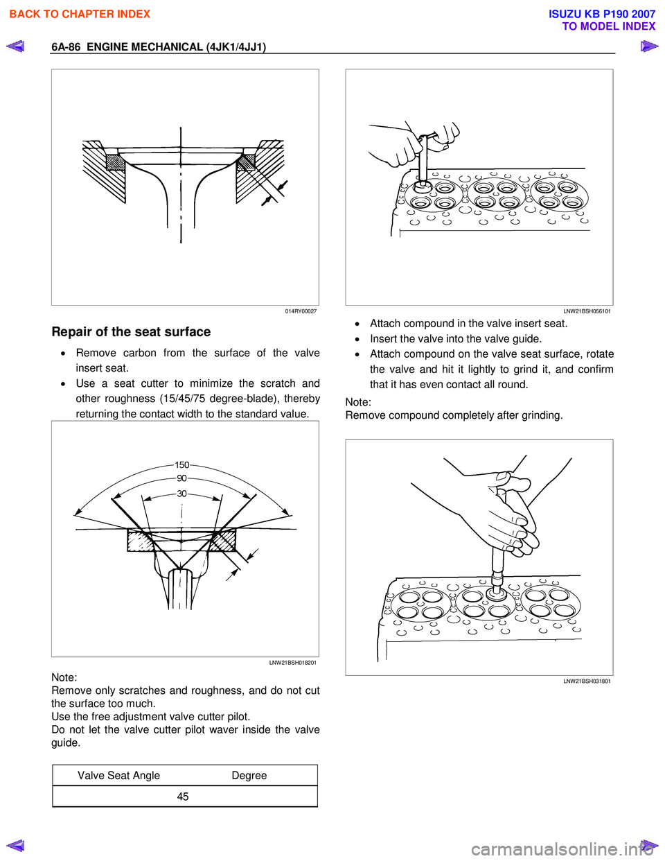
Repair of the seat surface
• Remove carbon from the surface of the valve
insert seat.
• Use a seat cutter to minimize the scratch and
other roughness (15/45/75 degree-blade), thereb
y
returning the contact width to the standard value.
LNW 21BSH018201
Note:
Remove only scratches and roughness, and do not cut
the surface too much.
Use the free adjustment valve cutter pilot.
Do not let the valve cutter pilot waver inside the valve
guide.
Valve Seat Angle Degree
45
LNW 21BSH056101
• Attach compound in the valve insert seat.
• Insert the valve into the valve guide.
•
Attach compound on the valve seat surface, rotate
the valve and hit it lightly to grind it, and confirm
that it has even contact all round.
Note:
Remove compound completely after grinding.
LNW 21BSH031801
BACK TO CHAPTER INDEX
TO MODEL INDEX
ISUZU KB P190 2007
Page 1518 of 6020
6A-158 ENGINE MECHANICAL (4JK1/4JJ1)
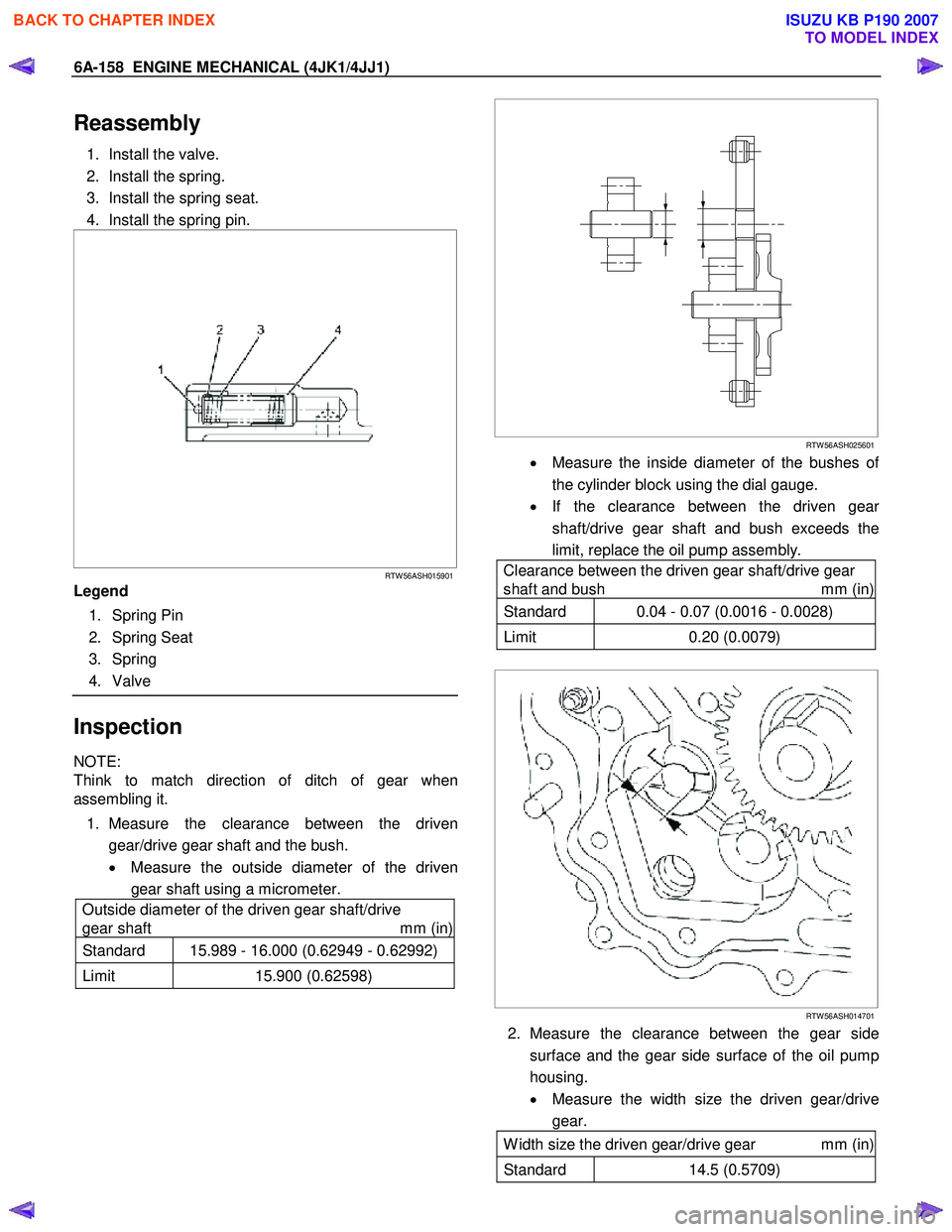
Reassembly
1. Install the valve.
2. Install the spring.
3. Install the spring seat.
4. Install the spring pin.
RTW 56ASH015901
Legend
1. Spring Pin
2. Spring Seat
3. Spring
4. Valve
Inspection
NOTE:
Think to match direction of ditch of gear when
assembling it.
1. Measure the clearance between the driven gear/drive gear shaft and the bush.
• Measure the outside diameter of the driven
gear shaft using a micrometer.
Outside diameter of the driven gear shaft/drive
gear shaft mm (in)
Standard 15.989 - 16.000 (0.62949 - 0.62992)
Limit 15.900 (0.62598)
RTW 56ASH025601
• Measure the inside diameter of the bushes of
the cylinder block using the dial gauge.
• If the clearance between the driven gea
r
shaft/drive gear shaft and bush exceeds the
limit, replace the oil pump assembly.
Clearance between the driven gear shaft/drive gear
shaft and bush mm (in)
Standard 0.04 - 0.07 (0.0016 - 0.0028)
Limit 0.20 (0.0079)
RTW 56ASH014701
2. Measure the clearance between the gear side
surface and the gear side surface of the oil pump
housing.
• Measure the width size the driven gear/drive
gear.
W idth size the driven gear/drive gear mm (in)
Standard 14.5 (0.5709)
BACK TO CHAPTER INDEX
TO MODEL INDEX
ISUZU KB P190 2007
Page 1669 of 6020
6E-52 ENGINE CONTROL SYSTEM (4JK1/4JJ1)
Desired EGR Position
This parameter displays EGR position desired by the
ECM based on current driving conditions. This can be
compared to the actual EGR position to determine
sensor accuracy or EGR control problems.
EGR Position
This parameter displays the EGR valve position
calculated by the ECM using the signal from EGR
position sensor. The scan tool will display a low
percentage when the EGR valve is closed, and a high
percentage when the ERG valve is opened.
EGR Position Sensor
This parameter displays the voltage signal sent to the
ECM from the EGR position sensor. EGR position
sensor is a range of value indicating a low voltage
when the EGR valve is closed, and a high voltage when
the EGR valve is opened.
Intake Throttle Solenoid Command
This parameter displays the intake throttle solenoid
valve control duty ratio based on inputs to the ECM
from various engine sensors. The scan tool will display
a lower percentage when the intake throttle solenoid
valve is controlled to open. The scan tool will display a
higher percentage when the intake throttle solenoid
valve is controlled to close.
Desired Intake Throttle Position
This parameter displays intake throttle position desired
by the ECM based on current driving conditions. This
can be compared to the actual intake throttle position to
determine sensor accuracy or intake throttle control
problems.
Intake Throttle Position
This parameter displays the intake throttle valve
position calculated by the ECM using the signal from
intake throttle position sensor. The scan tool will display
a low percentage when the intake throttle valve is
closed, and a high percentage when the intake throttle
valve is opened. Note that the intake throttle position
indicates over 100% if the solenoid is commanded
OFF.
Intake Throttle Position Sensor
This parameter displays the voltage signal sent to the
ECM from the intake throttle position sensor. Intake
throttle position sensor is a range of value indicating a
low voltage when the intake throttle valve is closed to a
high voltage when the intake throttle valve is opened.
Desired Injection Quantity
This parameter displays a total injection quantity (main
injection quantity + pre injection quantity) desired by
the ECM based on current driving conditions.
Main Injection Quantity
This parameter displays a main injection quantity
desired by the ECM based on current driving
conditions. Main Injection Timing
This parameter displays a main injection timing desired
by the ECM based on current driving conditions.
Main Injection On Time
This parameter displays the time the ECM turns ON the
fuel injectors. The scan tool will display a higher value
with a longer pulse width, or a lower value with a
shorter pulse width.
Pre Injection Quantity
This parameter displays a pilot injection quantity
desired by the ECM based on current driving
conditions.
Pre Injection Interval
This parameter displays a injection interval between
end of pilot injection and start of main injection desired
by the ECM based on current driving condition.
Fuel Compensation Cyl. 1 to 4
This parameter displays the adjustment of fuel volume
for each cylinder at low engine speed area as
calculated by the ECM. The scan tool will display a
negative value if the fuel volume is lowered. The scan
tool will display a positive value if the fuel volume is
increased. If there is a cylinder that is excessively high
or low value, it may indicate faulty fuel injector, weak or
slightly seized cylinder or an incorrectly programmed
fuel injector ID code.
Cylinder Balancing Update
This parameter displays the state of the fuel
compensation for each cylinder. Enabled indicates the
adjustment of fuel volume for each cylinder is being
executed by the ECM when the engine is idle speed,
the engine coolant temperature sensor, the intake air
temperature sensor, barometric pressure sensor and
the vehicle speed sensor inputs are normal state.
Fuel Supply Pump Status
This parameter displays the learning state of the fuel
supply pump. Not Learn indicates initialized state that is
replaced to a new ECM or adjustment value is reset.
After engine is warm upped, leaning will start at idle
speed. Learning indicates learning state. Learned
indicates learning process is completed state.
Rail Pressure Feedback Mode
This parameter displays the state of the fuel rail
pressure feedback to the ECM. Wait Mode indicates
the ignition switch is turned ON position. Feedback
Mode indicates the engine is during crank or run.
Shutoff Mode indicates the ignition switch is turned
OFF position.
Engine Mode
This parameter displays the state of engine. Ignition On
indicates the ignition switch is turned ON position.
Cranking indicates the engine is during crank. Running
indicates the engine is run. Off indicates the ignition
switch is tuned OFF position.
BACK TO CHAPTER INDEX
TO MODEL INDEX
ISUZU KB P190 2007
Page 1688 of 6020
ENGINE CONTROL SYSTEM (4JK1/4JJ1) 6E-71
DTC P0045 (Flash Code 33)
Circuit Description
The position of the turbocharger nozzle is controlled by
the ECM. The ECM utilizes a turbocharger nozzle
control solenoid valve and a boost pressure sensor to
control the turbocharger nozzles. When the engine is
not under load, the turbocharger nozzles are in an open
position, or no boost condition. When the engine is
under load, the ECM commands the control solenoid
valve to close the turbocharger nozzles, thus
increasing the boost. The ECM will vary the boost
dependant upon the load requirements of the engine.
The ECM uses a pulse width modulation (PWM) on the
control circuit to open and control the solenoid valve. If
the ECM detects an open circuit or short circuit on the
solenoid valve circuit, this DTC will set.
Condition for Running the DTC • The ignition switch is ON.
Condition for Setting the DTC
Either of following condition is met: • The ECM detects a low voltage condition on the turbocharger nozzle control solenoid circuit when
the solenoid is commanded OFF.
• The ECM detects a high voltage condition on the turbocharger nozzle control solenoid circuit when
the solenoid is commanded ON. Action Taken When the DTC Sets
• The ECM illuminates the MIL when the diagnostic runs and fails. Refer to DTC Type Definitions for
Action Taken When the DTC Sets - Type A.
• The ECM limits fuel injection quantity.
• The ECM inhibits pilot injection.
• The ECM inhibits cruise control.
Condition for Clearing the DTC • Refer to DTC Type Definitions for Condition for Clearing the MIL/ DTC - Type A.
Diagnostic Aids • If an intermittent condition is suspected, refer to Intermittent Conditions in this section.
Test description
The number below refers to the step number on the
Circuit/ System Testing.
4. If the solenoid control circuit between the ECM and
the solenoid is normal, the test lamp changes from
Bright to Dim when commanded from Increase to
Decrease.
Schematic Reference: Vacuum Hose Routing
Diagram and Engine Controls Schematics
Connector End View Reference: Engine Controls
Connector End Views or ECM Connector End Views
Circuit/ System Testing DTC P0045
Step Action Value(s)Yes No
1 Did you perform the Diagnostic System Check -
Engine Controls? —
Go to Step 2 Go to Diagnostic
System Check -
Engine Controls
2 1. Install a scan tool.
2. Turn OFF the ignition for 30 seconds.
3. Start the engine.
4. Monitor the DTC Information with a scan tool.
Does the DTC fail this ignition? —
Go to Step 3 Go to Diagnostic
Aids
3 1. Turn OFF the ignition.
2. Disconnect the turbocharger nozzle control solenoid valve harness connector.
3. Connect a test lamp between the ignition voltage feed circuit (pin 2 of E-106) and a
known good ground.
4. Turn ON the ignition, with the engine OFF.
Does the test lamp illuminate? —
Go to Step 4 Go to Step 5
BACK TO CHAPTER INDEX
TO MODEL INDEX
ISUZU KB P190 2007
Page 1914 of 6020
ENGINE CONTROL SYSTEM (4JK1/4JJ1) 6E-297
DTC P2621 or P2622 (Flash Code 94)
Circuit Description
The accelerator pedal position (APP) sensor is
mounted on the accelerator pedal control assembly.
The analogue APP signals are converted by the ECM
into a pulse width modulation (PWM) signal. This
converted signal is sent from the ECM to the TCM to
determine appropriate shift points depending on the
accelerator pedal pressing amount. If the ECM detects
an improper voltage level on the APP PWM signal
circuit, DTC P2621 or P2622 will set.
Condition for Running the DTC • The battery voltage is more than 9 volts.
• The ignition switch is ON.
Condition for Setting the DTC • The ECM detects a low voltage condition on the APP PWM signal circuit for longer than 3 seconds.
(DTC P2621) • The ECM detects a high voltage condition on the
APP PWM signal circuit for longer than 3 seconds.
(DTC P2622)
Action Taken When the DTC Sets • The ECM illuminates the MIL when the diagnostic runs and fails. Refer to DTC Type Definitions for
Action Taken When the DTC Sets - Type A.
Condition for Clearing the DTC • Refer to DTC Type Definitions for Condition for Clearing the MIL/ DTC - Type A.
Diagnostic Aids • If an intermittent condition is suspected, refer to Intermittent Conditions in this section.
Schematic Reference: Engine Controls Schematics
Connector End View Reference: Engine Controls
Connector End Views or ECM Connector End Views
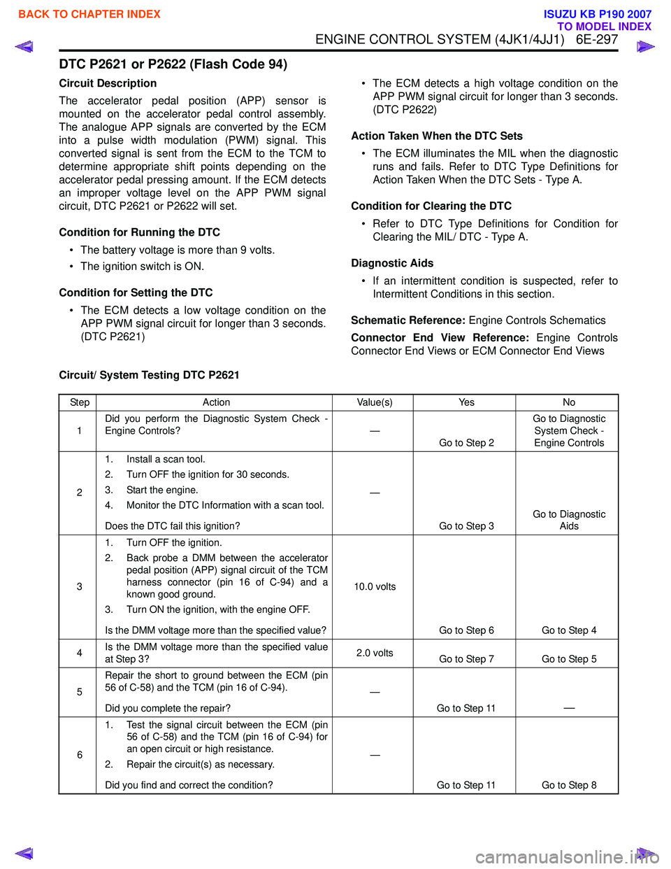
Circuit/ System Testing DTC P2621
Step Action Value(s)Yes No
1 Did you perform the Diagnostic System Check -
Engine Controls? —
Go to Step 2 Go to Diagnostic
System Check -
Engine Controls
2 1. Install a scan tool.
2. Turn OFF the ignition for 30 seconds.
3. Start the engine.
4. Monitor the DTC Information with a scan tool.
Does the DTC fail this ignition? —
Go to Step 3 Go to Diagnostic
Aids
3 1. Turn OFF the ignition.
2. Back probe a DMM between the accelerator pedal position (APP) signal circuit of the TCM
harness connector (pin 16 of C-94) and a
known good ground.
3. Turn ON the ignition, with the engine OFF.
Is the DMM voltage more than the specified value? 10.0 volts
Go to Step 6 Go to Step 4
4 Is the DMM voltage more than the specified value
at Step 3? 2.0 volts
Go to Step 7 Go to Step 5
5 Repair the short to ground between the ECM (pin
56 of C-58) and the TCM (pin 16 of C-94).
Did you complete the repair? —
Go to Step 11
—
61. Test the signal circuit between the ECM (pin
56 of C-58) and the TCM (pin 16 of C-94) for
an open circuit or high resistance.
2. Repair the circuit(s) as necessary.
Did you find and correct the condition? —
Go to Step 11 Go to Step 8
BACK TO CHAPTER INDEX
TO MODEL INDEX
ISUZU KB P190 2007
Page 1937 of 6020
6E-320 ENGINE CONTROL SYSTEM (4JK1/4JJ1)
Turbocharger Control System Check
Description
The position of the turbocharger nozzle is controlled by
the ECM. The ECM utilizes a turbocharger nozzle
control solenoid valve and a boost pressure sensor to
control the turbocharger nozzles. When the engine is
not under load, the turbocharger nozzles are in an open
position, or no boost condition. When the engine is
under load, the ECM commands the control solenoid
valve to close the turbocharger nozzles, thus
increasing the boost. The ECM will vary the boost
dependant upon the load requirements of the engine.
The ECM uses a pulse width modulation (PWM) on the
control circuit to open and control the solenoid valve. Notice:
• This Circuit/ System Testing is only applicable to high output engine.
Schematic Reference: Engine Controls Schematics
Connector End View Reference: Engine Controls
Connector End Views or ECM Connector End Views
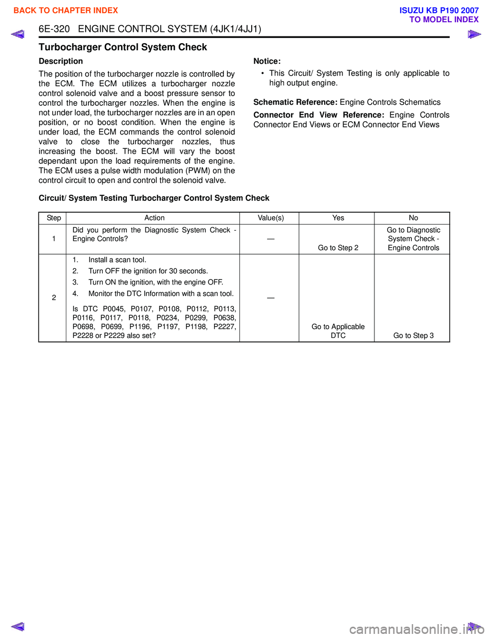
Circuit/ System Testing Turbocharger Control System Check
Step Action Value(s)Yes No
1 Did you perform the Diagnostic System Check -
Engine Controls? —
Go to Step 2 Go to Diagnostic
System Check -
Engine Controls
2 1. Install a scan tool.
2. Turn OFF the ignition for 30 seconds.
3. Turn ON the ignition, with the engine OFF.
4. Monitor the DTC Information with a scan tool.
Is DTC P0045, P0107, P0108, P0112, P0113,
P0116, P0117, P0118, P0234, P0299, P0638,
P0698, P0699, P1196, P1197, P1198, P2227,
P2228 or P2229 also set? —
Go to Applicable DTC Go to Step 3
BACK TO CHAPTER INDEX
TO MODEL INDEX
ISUZU KB P190 2007
Page 1983 of 6020
6E-366 ENGINE CONTROL SYSTEM (4JK1/4JJ1)
The EGR valve is mounted on the intake manifold. The
ECM controls the EGR valve opening based on the
engine running condition. The ECM controls the EGR
valve by controlling the solenoid. The solenoid is
controlled based on pulse width modulation (PWM)
signal sent from the ECM. A duty ratio change 0% to
appropriate percentage is EGR valve lift control. To
open the valve, duty ratio is increased. To close the
valve, duty ratio becomes small.
The EGR valve position is detected by the position
sensor, and relayed to the ECM. The position sensor
provides a signal to the ECM on the signal circuit,
which is relative to the position changes of the EGR
valve. The ECM should detect a low signal voltage at a
small lift amount or closed position. The ECM should
detect high signal voltage at a large lift amount.
Intake Throttle Valve
The intake throttle valve is located on the intake
manifold inlet. The ECM controls the intake throttle
valve opening based on the engine running condition.
The ECM controls the intake throttle valve by
controlling the solenoid. The solenoid is controlled
based on pulse width modulation (PWM) signal sent
from the ECM. A duty ratio change 0% to appropriate
percentage is intake throttle valve opening angle
control. To open the valve, duty ratio is increased. To
close the valve, duty ratio becomes small.
The intake throttle valve position is detected by the
position sensor, and relayed to the ECM. The position
sensor provides a signal to the ECM on the signal
circuit, which is relative to the position changes of the
intake throttle valve. The ECM should detect a low
signal voltage at a small opening amount or closed
position. The ECM should detect high signal voltage at
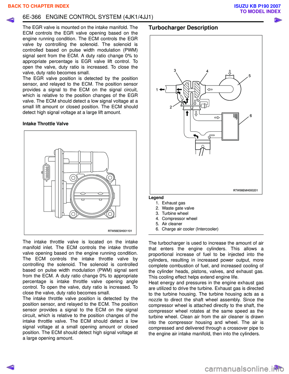
a large opening amount.Turbocharger Description
Legend
1. Exhaust gas
2. Waste gate valve
3. Turbine wheel
4. Compressor wheel
5. Air cleaner
6. Charge air cooler (Intercooler)
The turbocharger is used to increase the amount of air
that enters the engine cylinders. This allows a
proportional increase of fuel to be injected into the
cylinders, resulting in increased power output, more
complete combustion of fuel, and increased cooling of
the cylinder heads, pistons, valves, and exhaust gas.
This cooling effect helps extend engine life.
Heat energy and pressures in the engine exhaust gas
are utilized to drive the turbine. Exhaust gas is directed
to the turbine housing. The turbine housing acts as a
nozzle to direct the shaft wheel assembly. Since the
compressor wheel is attached directly to the shaft, the
compressor wheel rotates at the same speed as the
turbine wheel. Clean air from the air cleaner is drawn
into the compressor housing and wheel. The air is
compressed and delivered through a crossover pipe to
the engine air intake manifold, then into the cylinders.
RTW56ESH001101
RTW56EMH000201
1 3
2 4
5
6
BACK TO CHAPTER INDEX
TO MODEL INDEX
ISUZU KB P190 2007