Page 2094 of 6020
6A-80 ENGINE MECHANICAL (C24SE)
Cylinder Head (continued)
Valve System
Valve lifter valve play compensator
(hydraulic)
Valve rotators
(inlet or outlet) outlet
Valve play
(warm or cold) inlet mm 0
outlet mm 0
Cylinder head bottom, face parallelism mm 0.05
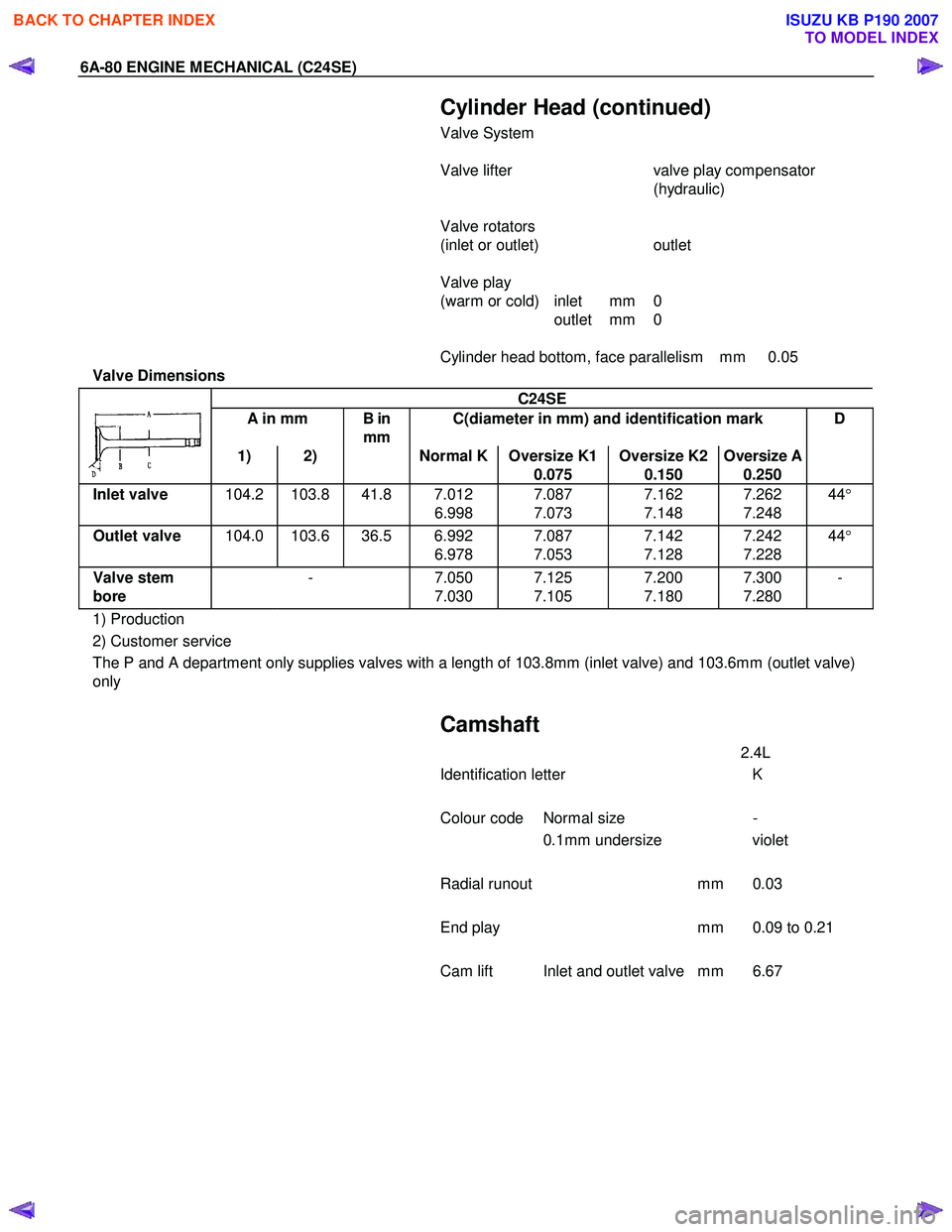
Valve Dimensions
C24SE
A in mm B in
mm C(diameter in mm) and identification mark D
1) 2) Normal K Oversize K1
0.075 Oversize K2
0.150 Oversize A
0.250
Inlet valve
104.2 103.8 41.8 7.012
6.998 7.087
7.073 7.162
7.148 7.262
7.248 44
°
Outlet valve 104.0 103.6 36.5 6.992
6.978 7.087
7.053 7.142
7.128 7.242
7.228 44
°
Valve stem
bore - 7.050
7.030 7.125
7.105 7.200
7.180 7.300
7.280 -
1) Production
2) Customer service
The P and A department only supplies valves with a length of 103.8mm (inlet valve) and 103.6mm (outlet valve)
only
Camshaft
2.4L
Identification letter K
Colour code Normal size -
0.1mm undersize violet
Radial runout mm 0.03
End play mm 0.09 to 0.21
Cam lift Inlet and outlet valve mm 6.67
BACK TO CHAPTER INDEX
TO MODEL INDEX
ISUZU KB P190 2007
Page 2097 of 6020
ENGINE MECHANICAL (C24SE) 6A-83
Crankshaft, Cylinder Block (continued)
Piston Rings
2.4L
Square ring Height mm 1.2
Tapered ring Height mm 1.5
Oil scraper Height mm 2.5
Ring gap offset 180 °
Note that the upper steel band ring gap is offset 25 to 50mm to
the left and the lower 25 to 50mm to the right opposite the
intermediate ring gap.
Piston Pin
Length mm 61.5
Diameter mm 21
Type Shrunk into con-rod
Play mm 2.4L
in piston 0.010-0.015
in con-rod none
Installation W hen installing piston pins,
heat con-rods to approx.
280 °C in oil bath. This
temperature should under no
circumstances be exceeded.
Crankshaft, Cylinder Block (continued)
The permissible weight variation of con-rods without piston and
bearing shell inside an engine is 8 g.
As the con-rods do not have balancing studs, reworking is not
possible.
Con-rods can only be replaced in sets.
BACK TO CHAPTER INDEX
TO MODEL INDEX
ISUZU KB P190 2007
Page 2099 of 6020
ENGINE MECHANICAL (C24SE) 6A-85
Piston Pins
Dimensions
Length mm
Diameter mm
61.5 21
Type Shank-fit in con-rod
Clearance
In piston mm
In con-rod mm 2.4L
0.010 to 0.015 0
Installation See operation “Con-rod, Replace”
BACK TO CHAPTER INDEX
TO MODEL INDEX
ISUZU KB P190 2007
Page 2133 of 6020
ENGINE FUEL (C24SE) 6C-15
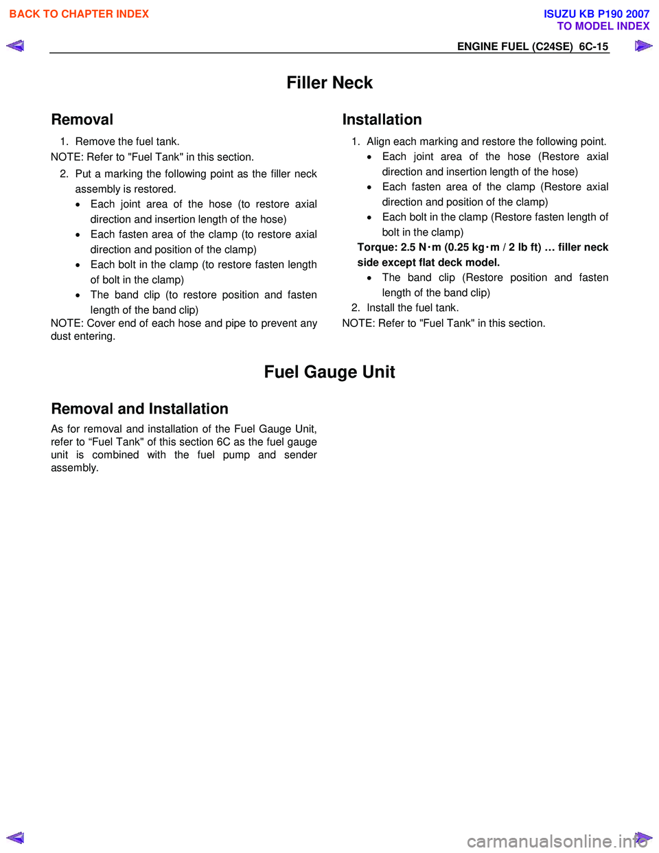
Filler Neck
Removal
1. Remove the fuel tank.
NOTE: Refer to "Fuel Tank" in this section.
2. Put a marking the following point as the filler neck
assembly is restored.
• Each joint area of the hose (to restore axial
direction and insertion length of the hose)
• Each fasten area of the clamp (to restore axial
direction and position of the clamp)
• Each bolt in the clamp (to restore fasten length
of bolt in the clamp)
• The band clip (to restore position and fasten
length of the band clip)
NOTE: Cover end of each hose and pipe to prevent an
y
dust entering.
Installation
1.
Align each marking and restore the following point.
• Each joint area of the hose (Restore axial
direction and insertion length of the hose)
• Each fasten area of the clamp (Restore axial
direction and position of the clamp)
• Each bolt in the clamp (Restore fasten length o
f
bolt in the clamp)
Torque: 2.5 N ・
・・
・
m (0.25 kg ・
・・
・
m / 2 lb ft) … filler neck
side except flat deck model. • The band clip (Restore position and fasten
length of the band clip)
2. Install the fuel tank.
NOTE: Refer to "Fuel Tank" in this section.
Fuel Gauge Unit
Removal and Installation
As for removal and installation of the Fuel Gauge Unit,
refer to “Fuel Tank" of this section 6C as the fuel gauge
unit is combined with the fuel pump and sende
r
assembly.
BACK TO CHAPTER INDEX
TO MODEL INDEX
ISUZU KB P190 2007
Page 2153 of 6020
STARTING AND CHARGING SYSTEM 6D3-5
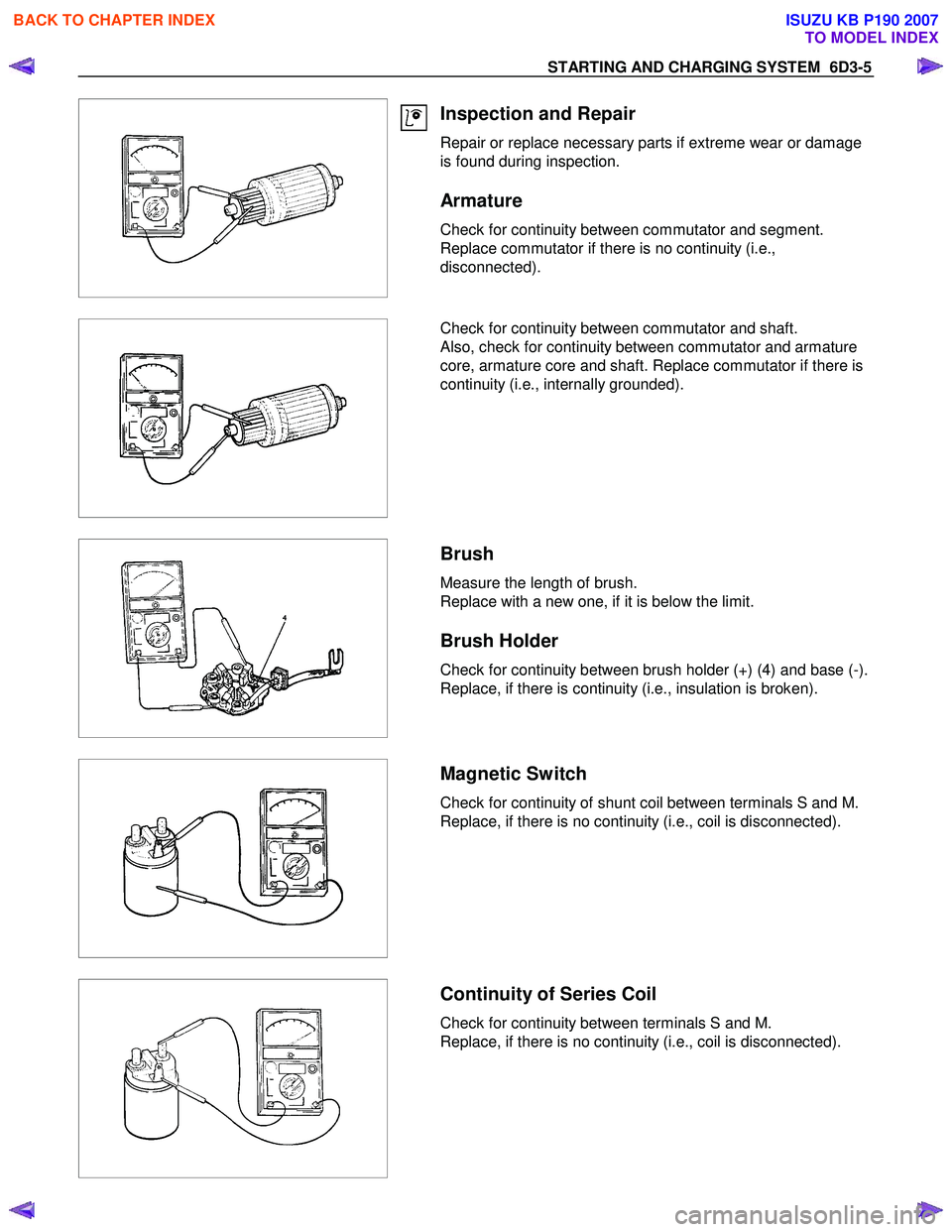
Inspection and Repair
Repair or replace necessary parts if extreme wear or damage
is found during inspection.
Armature
Check for continuity between commutator and segment.
Replace commutator if there is no continuity (i.e.,
disconnected).
Check for continuity between commutator and shaft.
Also, check for continuity between commutator and armature
core, armature core and shaft. Replace commutator if there is
continuity (i.e., internally grounded).
Brush
Measure the length of brush.
Replace with a new one, if it is below the limit.
Brush Holder
Check for continuity between brush holder (+) (4) and base (-).
Replace, if there is continuity (i.e., insulation is broken).
Magnetic Switch
Check for continuity of shunt coil between terminals S and M.
Replace, if there is no continuity (i.e., coil is disconnected).
Continuity of Series Coil
Check for continuity between terminals S and M.
Replace, if there is no continuity (i.e., coil is disconnected).
BACK TO CHAPTER INDEX
TO MODEL INDEX
ISUZU KB P190 2007
Page 2165 of 6020
STARTING AND CHARGING SYSTEM 6D3-17
fan.
4. Replacing the brushes (inbuilt regulator)
Check the brushes for length, this is measured from the brush
holder to the end of the brush along it's centre line. Also
inspect for any sideways wear. If worn replace both brushes.
The minimum length is 3.8mm. Inspect the brush springs for
signs of corrosion or loss of tension or uneven tension.
Replacing the brushes, using a soldering iron apply heat to the
soldered joints on the rear of the brush holder of the regulator,
using a small lever prise up the retaining tabs to release the
brush lead and spring. Thread the new brush lead up the
brush holder along with the spring, pull the lead through the
tabs until the brush is protruding 12mm from the holder.
Bend down the tabs and solder the brush lead taking care not
to allow the solder to run up the lead which will reduce
flexibility. Use 60/40 resin cored solder.
5. Ball bearing
Please note the bearings used in this KCA generator are a
high
tolerance type, only fully sealed bearings of the same
specification are to be used as replacements. It is
recommended that the bearings be replaced during the
reconditioning process to restore the unit to original
specification.
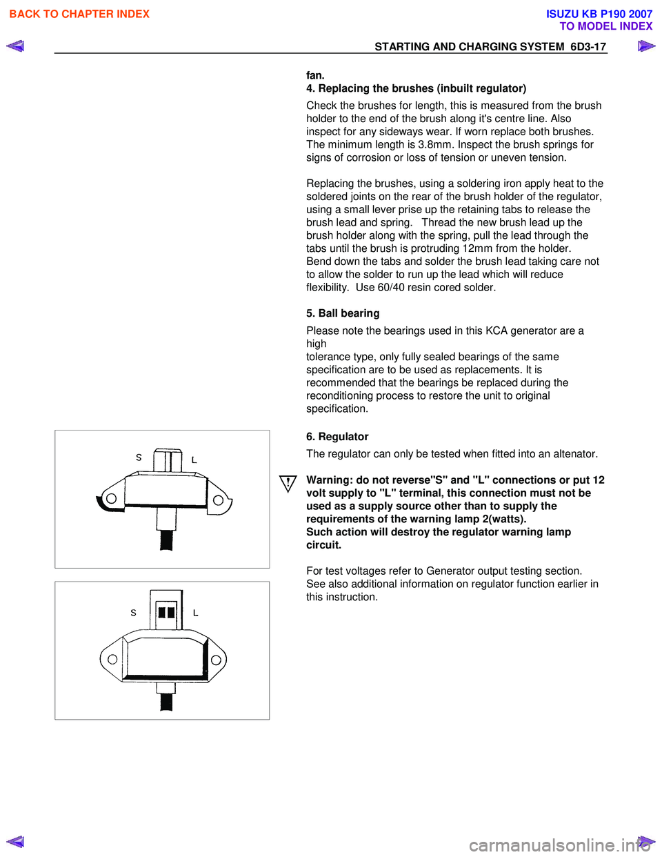
6. Regulator
The regulator can only be tested when fitted into an altenator.
Warning: do not reverse"S" and "L" connections or put 12
volt supply to "L" terminal, this connection must not be
used as a supply source other than to supply the
requirements of the warning lamp 2(watts).
Such action will destroy the regulator warning lamp
circuit.
For test voltages refer to Generator output testing section.
See also additional information on regulator function earlier in
this instruction.
BACK TO CHAPTER INDEX
TO MODEL INDEX
ISUZU KB P190 2007
Page 2169 of 6020
STARTING AND CHARGING SYSTEM 6D3-21
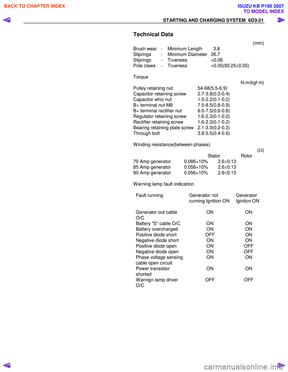
Technical Data
(mm)
Brush wear - Minimum Length 3.8
Sliprings - Minimum Diameter 26.7
Sliprings - Trueness <0.06
Pole claws - Trueness <0.05(93.25 ±0.05)
Torque N.m(kgf⋅m)
Pulley retaining nut 54-68(5.5-6.9)
Capacitor retaining screw 2.7-3.8(0.3-0.4)
Capacitor whiz nut 1.5-2.2(0.1-0.2)
B+ terminal nut M8 7.5-8.5(0.8-0.9)
B+ terminal rectifier nut 6.0-7.5(0.6-0.8)
Regulator retaining screw 1.6-2.3(0.1-0.2)
Rectifier retaining screw 1.6-2.3(0.1-0.2)
Bearing retaining plate screw 2.1-3.0(0.2-0.3)
Through bolt 3.8-5.5(0.4-0.6)
W inding resistance(between phases) (Ω )
Stator Rotor
70 Amp generator 0.086+10% 2.6 ±0.13
85 Amp generator 0.058+10% 2.6 ±0.13
90 Amp generator 0.056+10% 2.6 ±0.13
W arning lamp fault indication
Fault running Generator not
running Ignition ON Generator
Iginiton ON
Generator out cable
O/C ON
ON
Battery "S" cable O/C ONON
Battery overcharged ONON
Positive diode short OFFON
Negative diode short ONON
Positive diode open ONOFF
Negative diode open ONOFF
Phase voltage sensing ONON
cable open circuit
Power transistor
shorted ON
ON
W arnign lamp driver
O/C OFF
OFF
BACK TO CHAPTER INDEX
TO MODEL INDEX
ISUZU KB P190 2007
Page 2281 of 6020
ENGINE DRIVEABILITY AND EMISSIONS 6E–111
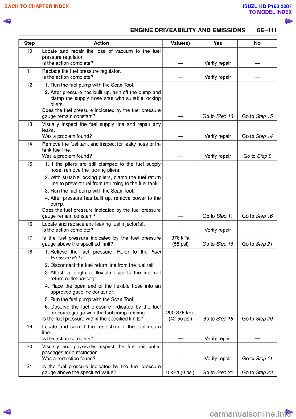
10 Locate and repair the loss of vacuum to the fuelpressure regulator.
Is the action complete? — Verify repair —
11 Replace the fuel pressure regulator. Is the action complete? — Verify repair —
12 1. Run the fuel pump with the Scan Tool. 2. After pressure has built up, turn off the pump andclamp the supply hose shut with suitable locking
pliers.
Does the fuel pressure indicated by the fuel pressure
gauge remain constant? — Go to Step 13Go to Step 15
13 Visually inspect the fuel supply line and repair any leaks.
Was a problem found? — Verify repair Go to Step 14
14 Remove the fuel tank and inspect for leaky hose or in- tank fuel line.
Was a problem found? — Verify repair Go to Step 8
15 1. If the pliers are still clamped to the fuel supply hose, remove the locking pliers.
2. With suitable locking pliers, clamp the fuel return line to prevent fuel from returning to the fuel tank.
3. Run the fuel pump with the Scan Tool.
4. After pressure has built up, remove power to the pump.
Does the fuel pressure indicated by the fuel pressure
gauge remain constant? — Go to Step 11Go to Step 16
16 Locate and replace any leaking fuel injector(s). Is the action complete? — Verify repair —
17 Is the fuel pressure indicated by the fuel pressure gauge above the specified limit? 376 kPa
(55 psi) Go to Step 18Go to Step 21
18 1. Relieve the fuel pressure. Refer to the Fuel
Pressure Relief .
2. Disconnect the fuel return line from the fuel rail.
3. Attach a length of flexible hose to the fuel rail return outlet passage.
4. Place the open end of the flexible hose into an approved gasoline container.
5. Run the fuel pump with the Scan Tool.
6. Observe the fuel pressure indicated by the fuel pressure gauge with the fuel pump running.
Is the fuel pressure within the specified limits? 290-376 kPa
(42-55 psi) Go to Step 19Go to Step 20
19 Locate and correct the restriction in the fuel return line.
Is the action complete? — Verify repair —
20 Visually and physically inspect the fuel rail outlet passages for a restriction.
Was a restriction found? — Verify repair Go to Step 11
21 Is the fuel pressure indicated by the fuel pressure gauge above the specified value? 0 kPa (0 psi) Go to Step 22Go to Step 23
Step
Action Value(s) Yes No
BACK TO CHAPTER INDEX
TO MODEL INDEX
ISUZU KB P190 2007