2007 ISUZU KB P190 length
[x] Cancel search: lengthPage 3066 of 6020
Engine Mechanical – V6 Page 6A1–289
Page 6A1–289
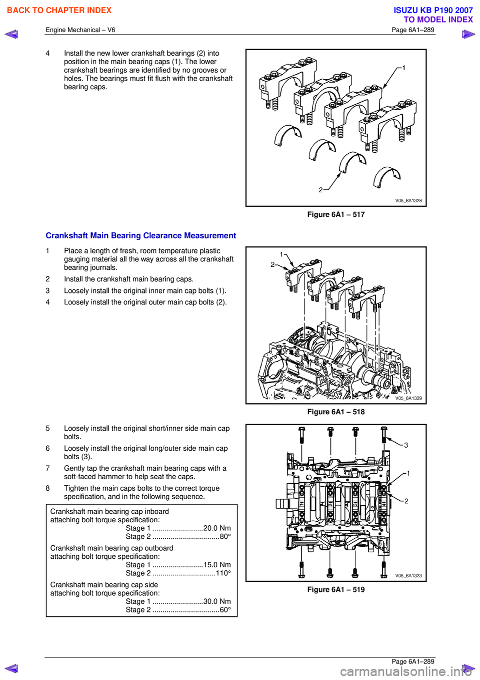
4 Install the new lower crankshaft bearings (2) into
position in the main bearing caps (1). The lower
crankshaft bearings are ident ified by no grooves or
holes. The bearings must fit flush with the crankshaft
bearing caps.
Figure 6A1 – 517
Crankshaft Main Bearing Clearance Measurement
1 Place a length of fresh, room temperature plastic
gauging material all the way across all the crankshaft
bearing journals.
2 Install the crankshaft main bearing caps.
3 Loosely install the original inner main cap bolts (1).
4 Loosely install the original outer main cap bolts (2).
Figure 6A1 – 518
5 Loosely install the original short/inner side main cap bolts.
6 Loosely install the original long/outer side main cap
bolts (3).
7 Gently tap the crankshaft main bearing caps with a soft-faced hammer to help seat the caps.
8 Tighten the main caps bolts to the correct torque specification, and in the following sequence.
Crankshaft main bearing cap inboard
attaching bolt torque specification:
Stage 1 .........................20.0 Nm
Stage 2................................. 80°
Crankshaft main bearing cap outboard
attaching bolt torque specification:
Stage 1 .........................15.0 Nm
Stage 2............................... 110°
Crankshaft main bearing cap side
attaching bolt torque specification:
Stage 1 .........................30.0 Nm
Stage 2................................. 60°
Figure 6A1 – 519
BACK TO CHAPTER INDEX
TO MODEL INDEX
ISUZU KB P190 2007
Page 3083 of 6020
Engine Mechanical – V6 Page 6A1–306
Page 6A1–306
NOTE
• During the tapping pr ocess, repeatedly
remove the tap and clean the swarf from the
hole and the flutes of the tap.
• Ensure the tap has created full threads at
least to the depth equal to the insert length.
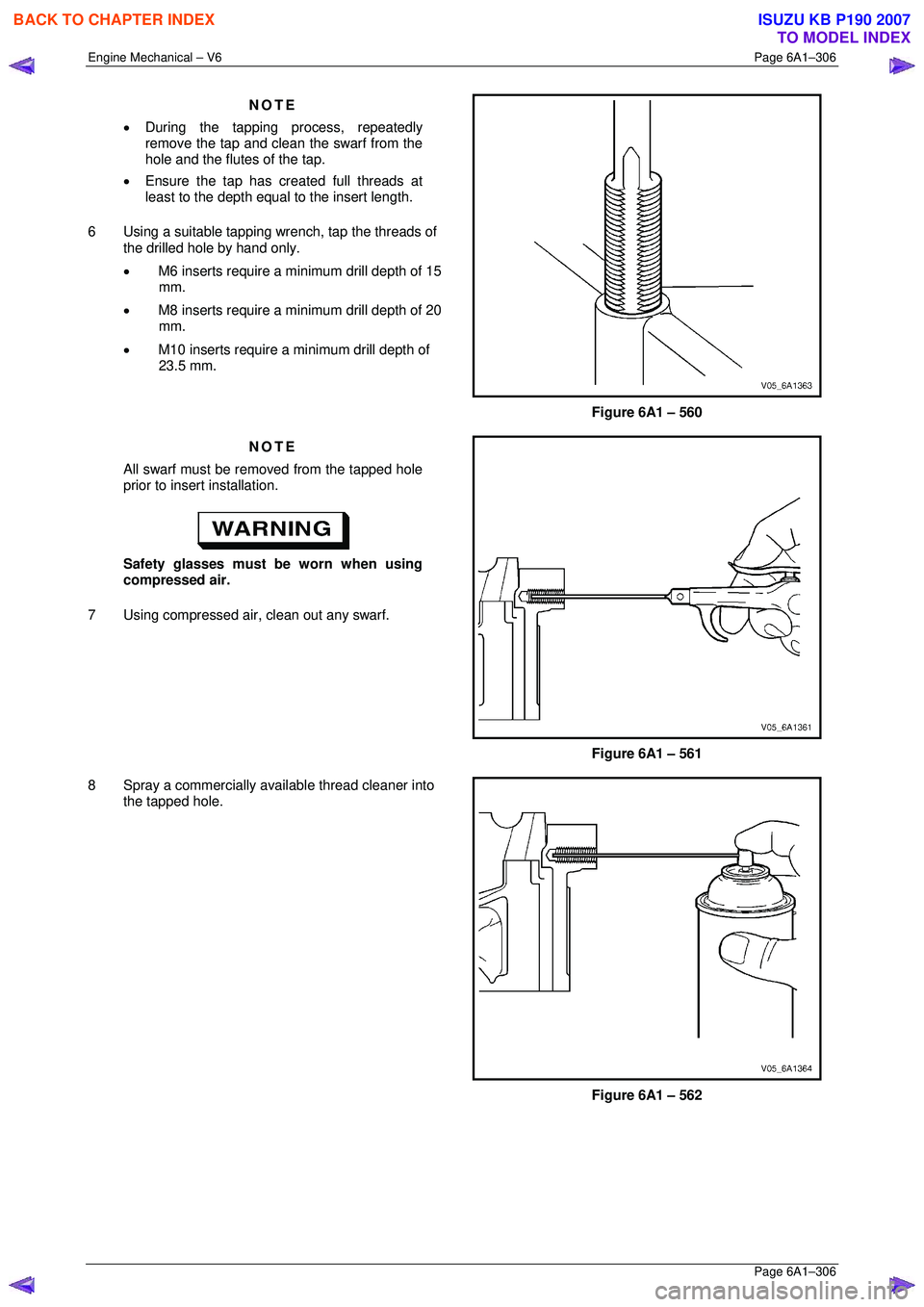
6 Using a suitable tapping wr ench, tap the threads of
the drilled hole by hand only.
• M6 inserts require a minimum drill depth of 15
mm.
• M8 inserts require a minimum drill depth of 20
mm.
• M10 inserts require a minimum drill depth of
23.5 mm.
Figure 6A1 – 560
NOTE
All swarf must be removed from the tapped hole
prior to insert installation.
Safety glasses must be worn when using
compressed air.
7 Using compressed air, clean out any swarf.
Figure 6A1 – 561
8 Spray a commercially available thread cleaner into the tapped hole.
Figure 6A1 – 562
BACK TO CHAPTER INDEX
TO MODEL INDEX
ISUZU KB P190 2007
Page 3089 of 6020
Engine Mechanical – V6 Page 6A1–312
Page 6A1–312
NOTE
• During the tapping pr ocess, repeatedly
remove the tap and clean the swarf from the
hole and the flutes of the tap.
• Ensure the tap has created full threads at
least to the depth equal to the insert length.
CAUTION
Do not remove the fixture plate during the
machining and installation processes of the
insert.
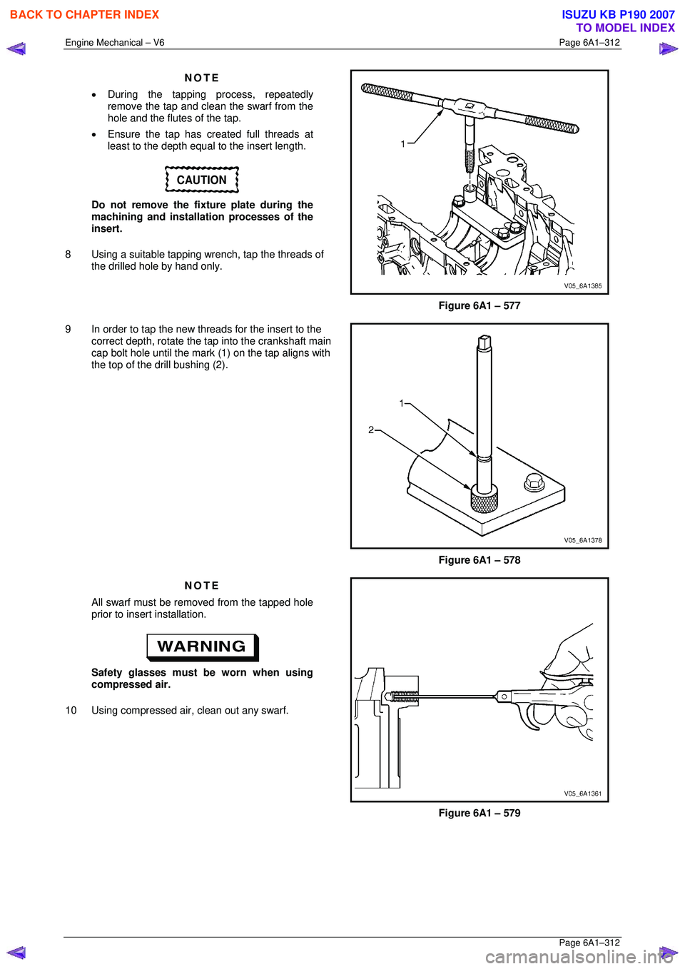
8 Using a suitable tapping wr ench, tap the threads of
the drilled hole by hand only.
Figure 6A1 – 577
9 In order to tap the new threads for the insert to the correct depth, rotate the t ap into the crankshaft main
cap bolt hole until the mark (1) on the tap aligns with
the top of the drill bushing (2).
Figure 6A1 – 578
NOTE
All swarf must be removed from the tapped hole
prior to insert installation.
Safety glasses must be worn when using
compressed air.
10 Using compressed air, clean out any swarf.
Figure 6A1 – 579
BACK TO CHAPTER INDEX
TO MODEL INDEX
ISUZU KB P190 2007
Page 3094 of 6020
Engine Mechanical – V6 Page 6A1–317
Page 6A1–317
NOTE
During the drilling process, repeatedly remove
the drill and clean swarf from the hole and the
flutes of the drill.
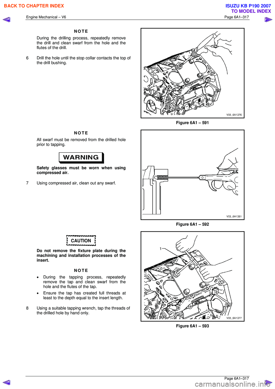
6 Drill the hole until the stop co llar contacts the top of
the drill bushing.
Figure 6A1 – 591
NOTE
All swarf must be removed from the drilled hole
prior to tapping.
Safety glasses must be worn when using
compressed air.
7 Using compressed air, clean out any swarf.
Figure 6A1 – 592
CAUTION
Do not remove the fixture plate during the
machining and installation processes of the
insert.
NOTE
• During the tapping pr ocess, repeatedly
remove the tap and clean swarf from the
hole and the flutes of the tap.
• Ensure the tap has created full threads at
least to the depth equal to the insert length.
8 Using a suitable tapping wr ench, tap the threads of
the drilled hole by hand only.
Figure 6A1 – 593
BACK TO CHAPTER INDEX
TO MODEL INDEX
ISUZU KB P190 2007
Page 3124 of 6020
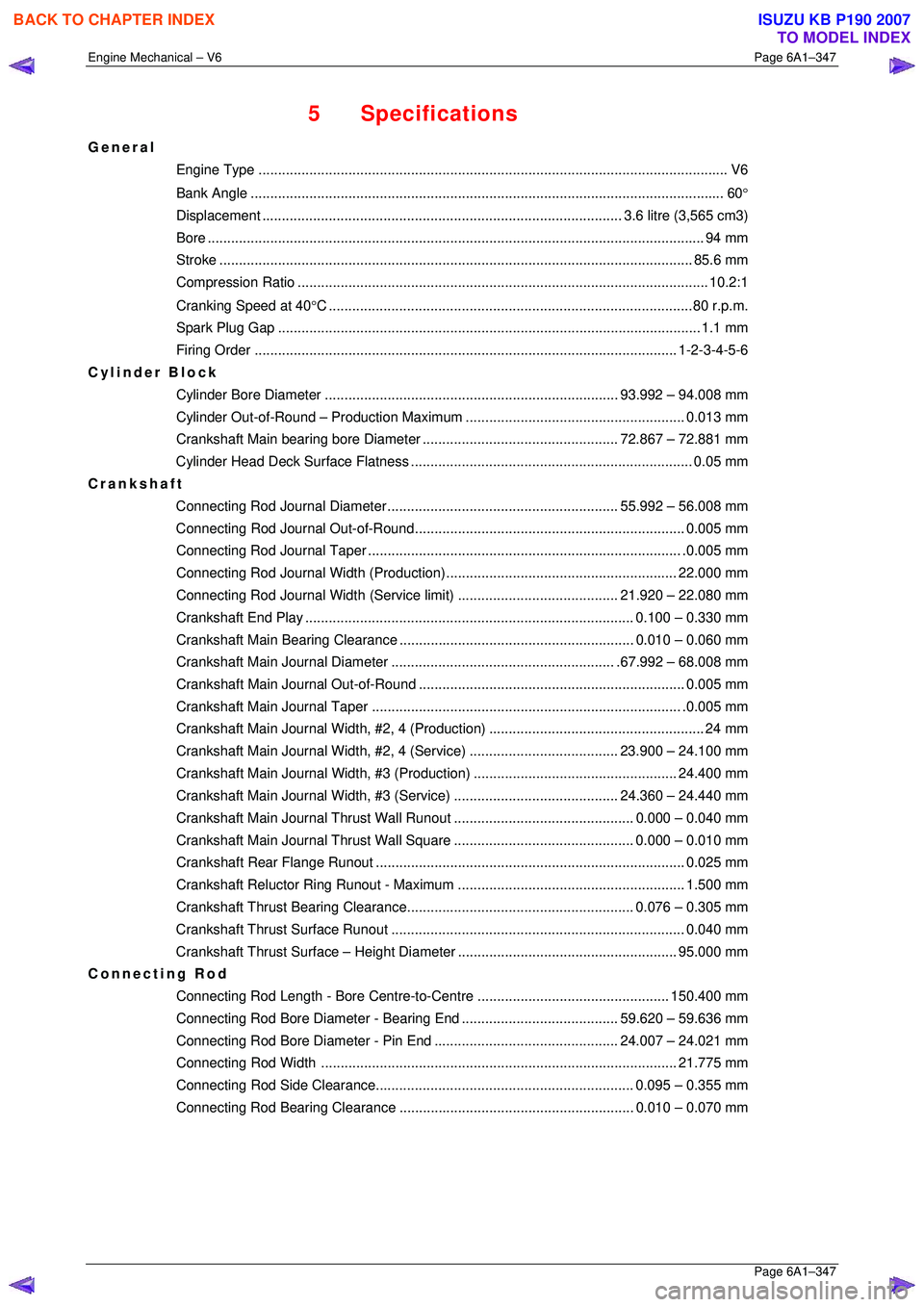
Engine Mechanical – V6 Page 6A1–347
Page 6A1–347
5 Specifications
General
Engine Type .................................................................................................................... .... V6
Bank An gle ..................................................................................................................... .... 60°
Displacement ............................................................................................ 3.6 litre (3,565 cm3)
Bore ........................................................................................................................... .... 94 mm
Stroke ......................................................................................................................... 85.6 mm
Compression Ratio......................................................................................................... 10. 2:1
Cranking Speed at 40 °C .............................................................................................80 r.p.m.
Spark Plug Gap ............................................................................................................ 1.1 mm
Firing Order ............................................................................................................ 1- 2-3-4-5-6
Cylinder Block
Cylinder Bore Diame ter ........................................................................... 93.992 – 94.008 mm
Cylinder Out-of-Round – Pr oduction Maximum ........................................................ 0.013 mm
Crankshaft Main bearing bor e Diameter .................................................. 72. 867 – 72.881 mm
Cylinder Head Deck Surf ace Flatness ........................................................................ 0. 05 mm
Crankshaft
Connecting Rod Journal Diameter........................................................... 55. 992 – 56.008 mm
Connecting Rod Journa l Out-of-Round..................................................................... 0.005 mm
Connecting Rod Jour nal Taper................................................................................ .0. 005 mm
Connecting Rod Journal Width (Production)........................................................... 22.000 mm
Connecting Rod Journal Width (Service limit)......................................... 21. 920 – 22.080 mm
Crankshaft End Pl ay .................................................................................... 0.100 – 0.330 mm
Crankshaft Main Bearing Clearance ............................................................ 0.010 – 0.060 mm
Crankshaft Main Journal Diameter......................................................... .67. 992 – 68.008 mm
Crankshaft Main Journa l Out-of-Round .................................................................... 0.005 mm
Crankshaft Main Journal Taper ............................................................................... .0. 005 mm
Crankshaft Main Journal Width, #2, 4 (Pr oduction)....................................................... 24 mm
Crankshaft Main Journal Width, #2, 4 (Service)...................................... 23. 900 – 24.100 mm
Crankshaft Main Journal Wi dth, #3 (Production) .................................................... 24.400 mm
Crankshaft Main Journal Width, #3 (Service).......................................... 24. 360 – 24.440 mm
Crankshaft Main Journal Thru st Wall Runout.............................................. 0.
000 – 0.040 mm
Crankshaft Main Journal Thru st Wall Square.............................................. 0. 000 – 0.010 mm
Crankshaft Rear Fl ange Runout............................................................................... 0. 025 mm
Crankshaft Reluctor Ring Ru nout - Maximum .......................................................... 1.500 mm
Crankshaft Thrust Bearin g Clearance.......................................................... 0. 076 – 0.305 mm
Crankshaft Thrust Su rface Runout........................................................................... 0. 040 mm
Crankshaft Thrust Surface – Height Diameter ........................................................ 95.000 mm
Connecting Rod
Connecting Rod Length - Bore Centre-to-Centre ................................................. 150.400 mm
Connecting Rod Bore Diameter - Bearing End........................................ 59. 620 – 59.636 mm
Connecting Rod Bore Diamet er - Pin End............................................... 24. 007 – 24.021 mm
Connecting Rod Width ........................................................................................... 21.775 mm
Connecting Rod Side Cl earance.................................................................. 0.095 – 0.355 mm
Connecting Rod Bearing Clearance ............................................................ 0.010 – 0.070 mm
BACK TO CHAPTER INDEX
TO MODEL INDEX
ISUZU KB P190 2007
Page 3125 of 6020
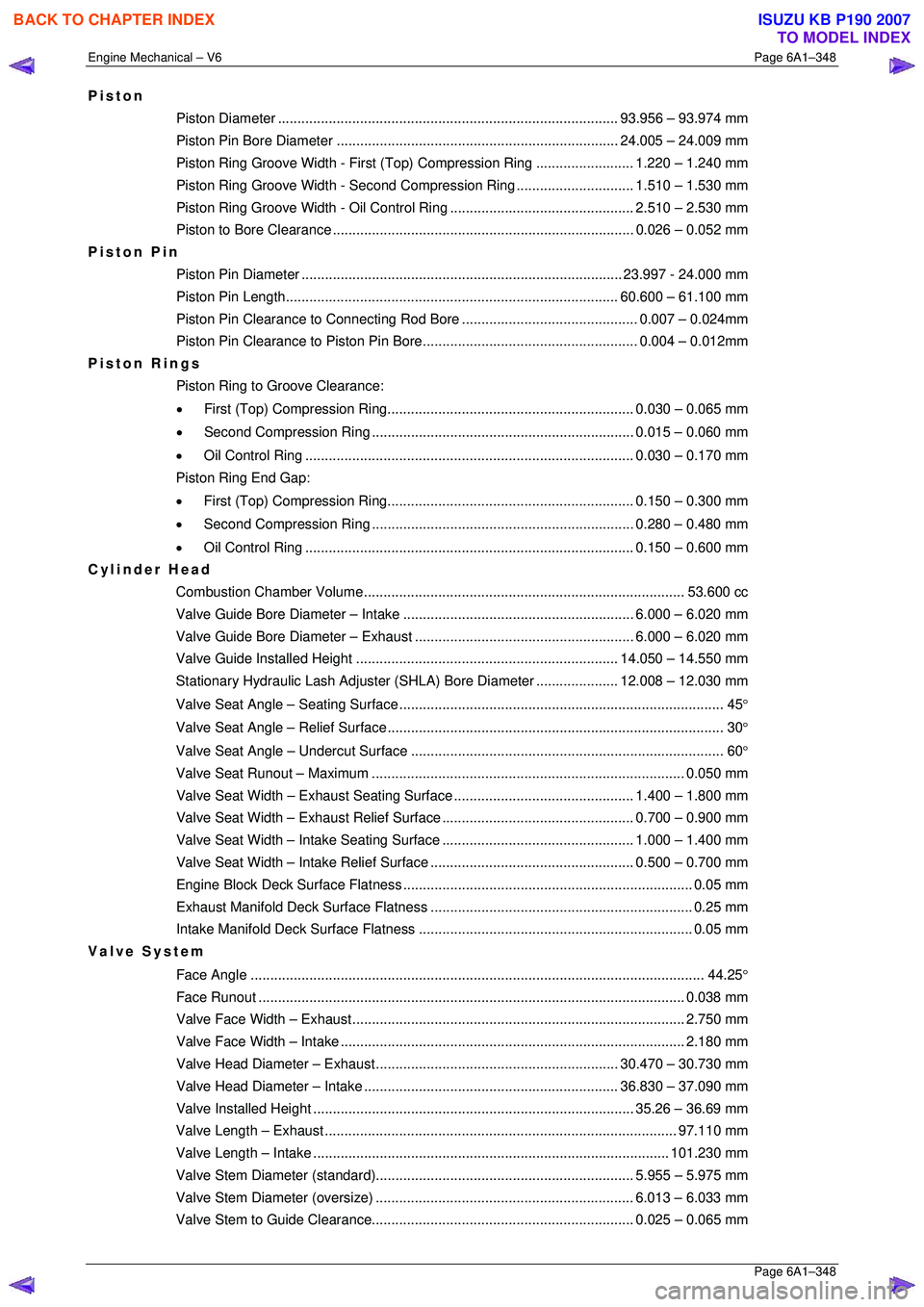
Engine Mechanical – V6 Page 6A1–348
Page 6A1–348
Piston
Piston Diameter ....................................................................................... 93. 956 – 93.974 mm
Piston Pin Bore Diame ter ........................................................................ 24.005 – 24.009 mm
Piston Ring Groove Width - First (Top) Compression Ring ......................... 1.220 – 1.240 mm
Piston Ring Groove Width - Second Compression Ring.............................. 1. 510 – 1.530 mm
Piston Ring Groove Width - Oil Control Ring ............................................... 2. 510 – 2.530 mm
Piston to Bore Clear ance ............................................................................. 0.026 – 0.052 mm
Piston Pin
Piston Pin Diamet er .................................................................................. 23.997 - 24.000 mm
Piston Pin Length ..................................................................................... 60. 600 – 61.100 mm
Piston Pin Clearance to Connec ting Rod Bore............................................. 0. 007 – 0.024mm
Piston Pin Clearance to Pist on Pin Bore....................................................... 0. 004 – 0.012mm
Piston Rings
Piston Ring to Groove Clearance:
• First (Top) Compression Ring............................................................... 0. 030 – 0.065 mm
• Second Compression Ring ................................................................... 0.015 – 0.060 mm
• Oil Control Ring .................................................................................... 0. 030 – 0.170 mm
Piston Ring End Gap:
• First (Top) Compression Ring............................................................... 0. 150 – 0.300 mm
• Second Compression Ring ................................................................... 0.280 – 0.480 mm
• Oil Control Ring .................................................................................... 0. 150 – 0.600 mm
Cylinder Head
Combustion Chambe r Volume.................................................................................. 53. 600 cc
Valve Guide Bore Diameter – Intake ........................................................... 6.000 – 6.020 mm
Valve Guide Bore Diameter – Exhaust ........................................................ 6.000 – 6.020 mm
Valve Guide Installed Height................................................................... 14. 050 – 14.550 mm
Stationary Hydraulic Lash Adjuster (S HLA) Bore Diameter .....................12.008 – 12.030 mm
Valve Seat Angle – Seating Surface ................................................................................... 45 °
Valve Seat Angle – Relief Surface...................................................................................... 30 °
Valve Seat Angle – Un dercut Surface ................................................................................ 60 °
Valve Seat Runout – Maximum................................................................................ 0. 050 mm
Valve Seat Width – Exhaust S eating Surface.............................................. 1. 400 – 1.800 mm
Valve Seat Width – Exhaust Re lief Surface................................................. 0. 700 – 0.900 mm
Valve Seat Width – Intake Se ating Surface................................................. 1. 000 – 1.400 mm
Valve Seat Width – Intake Relief Surface.................................................... 0. 500 – 0.700 mm
Engine Block Deck Surf ace Flatness .......................................................................... 0. 05 mm
Exhaust Manifold Deck Su rface Flatness ................................................................... 0. 25 mm
Intake Manifold Deck Su rface Flatness ...................................................................... 0. 05 mm
Valve System
Face Angle .................................................................................................................... 4 4.25°
Face Run out ............................................................................................................. 0.038 mm
Valve Face Width – Exhaust..................................................................................... 2. 750 mm
Valve Face Width – Intake........................................................................................ 2. 180 mm
Valve Head Diameter – Ex haust .............................................................. 30.470 – 30.730 mm
Valve Head Diameter – Intake ................................................................. 36. 830 – 37.090 mm
Valve Installed He ight .................................................................................. 35.26 – 36.69 mm
Valve Length – Exhaust.......................................................................................... 97. 110 mm
Valve Length – Intake ........................................................................................... 101.230 mm
Valve Stem Diameter (s tandard).................................................................. 5. 955 – 5.975 mm
Valve Stem Diameter (o versize).................................................................. 6.013 – 6.033 mm
Valve Stem to Guide Clearance................................................................... 0. 025 – 0.065 mm
BACK TO CHAPTER INDEX
TO MODEL INDEX
ISUZU KB P190 2007
Page 3161 of 6020
Engine Cooling – V6 Engine Page 6B1–26
10 Pressure test the cooling system. Refer to 3.7 Pressure Testing in this Section.
Engine
Refer to ‘
‘‘
‘
Environmental Issues ’
’’
’
in 3.1
Service Notes, before draining the coolant.
1 Drain the cooling system. Refer to 3.3 Draining and Filling Cooling System in this Section.
Always wear eye protection when working
with spring-type hose clamps. Failure to do
so may result in eye injury.
2 Remove the upper and lower radiator hoses from the coolant outlet housing and coolant inlet pipe connections. Refer to Figure 6B1 – 22.
3 Remove the thermostat housing from the rear of the engine block. Refer to 6A1 Engine Mechanical – V6..
4 Remove the thermostat from the thermostat housing and reinstall the housing to the rear of the intake manifold. Refer to 3.8 Thermostat in this Section.
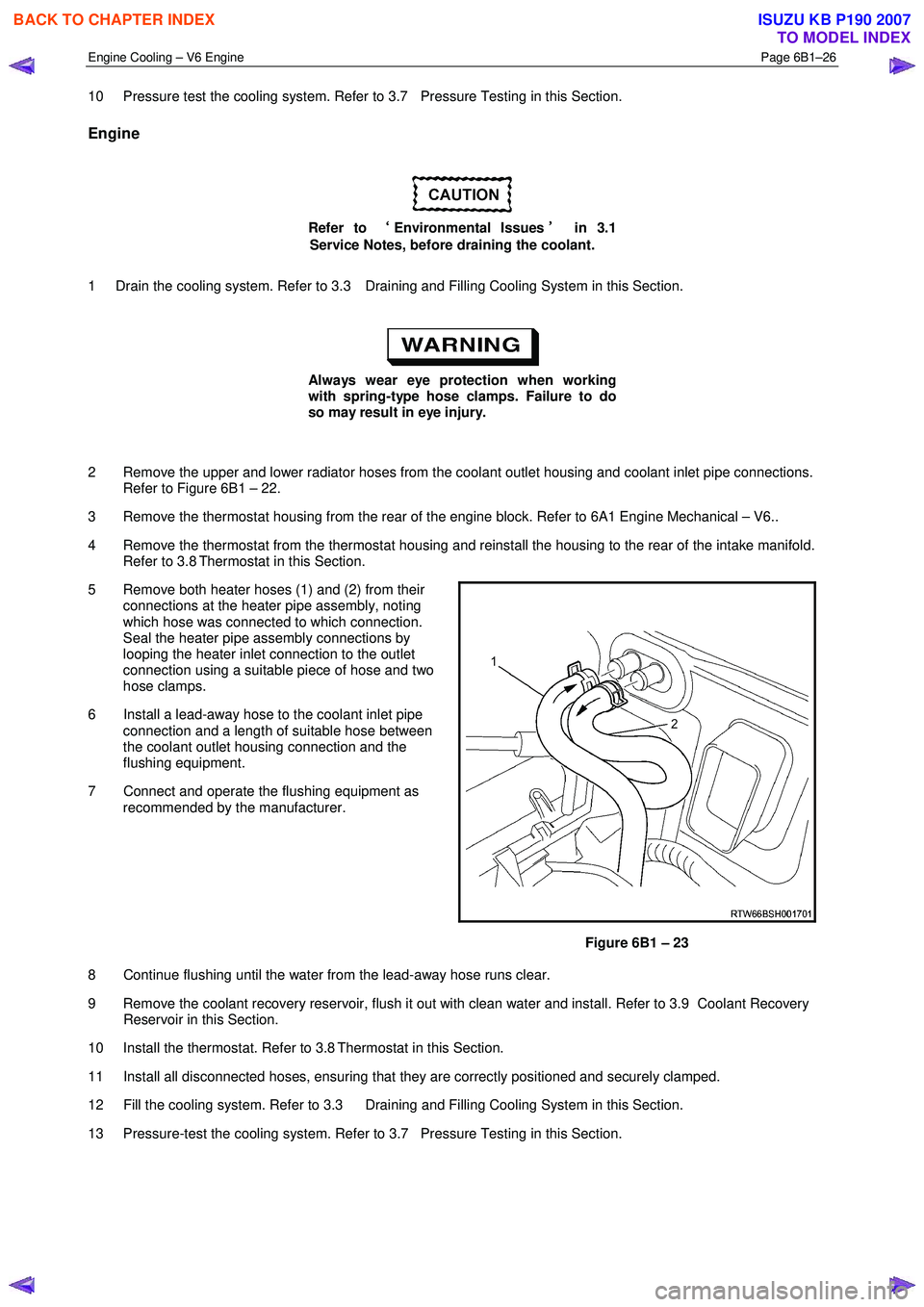
5 Remove both heater hoses (1) and (2) from their connections at the heater pipe assembly, noting
which hose was connected to which connection.
Seal the heater pipe assembly connections by
looping the heater inlet connection to the outlet
connection using a suitable piece of hose and two
hose clamps.
6 Install a lead-away hose to the coolant inlet pipe connection and a length of suitable hose between
the coolant outlet housing connection and the
flushing equipment.
7 Connect and operate the flushing equipment as recommended by the manufacturer.
Figure 6B1 – 23
8 Continue flushing until the water from the lead-away hose runs clear.
9 Remove the coolant recovery reservoir, flush it out with clean water and install. Refer to 3.9 Coolant Recovery Reservoir in this Section.
10 Install the thermostat. Refer to 3.8 Thermostat in this Section.
11 Install all disconnected hoses, ensuring that they are correctly positioned and securely clamped.
12 Fill the cooling system. Refer to 3.3 Draining and Filling Cooling System in this Section.
13 Pressure-test the cooling system. Refer to 3.7 Pressure Testing in this Section.
BACK TO CHAPTER INDEX
TO MODEL INDEX
ISUZU KB P190 2007
Page 3315 of 6020
Engine Management – V6 – Diagnostics Page 6C1-2–37
6 Functional Checks
6.1 General Information
The items detailed in the following pages are to be used when there is a customer complaint and there are no diagnostic
trouble codes set, or one or more of the Tech 2 data values are not within the typical values. They are also to be used
when instructed from a DTC table. Before using these tables, you should refer to 5 Symptoms Diagnostics in this
Section, which may direct you to using the following functional checks.
The purpose of these tables is to diagnose engine control module (ECM) controlled components or sub-systems that do
not have diagnostic trouble codes assigned to them. Another purpose of these tables is for Technicians who feel
confident that a particular part of the sub-system is not operating properly and wants only to check that particular item
for proper operation without going through lengthy diagnostic procedures.
6.2 Fuel Injector Coil Test
The fuel injector coil test is divided into two parts. Begin by performing the fuel injector coil quick test. Then only perform
the Injector Coil Test – W ith Special Tool J39021 procedure if the quick test determines that there is a faulty fuel injector.
Fuel Injector Coil Quick Test
Test Description
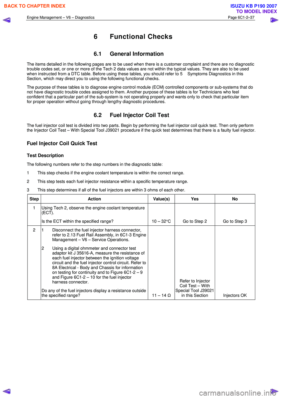
The following numbers refer to the step numbers in the diagnostic table:
1 This step checks if the engine coolant temperature is within the correct range.
2 This step tests each fuel injector resistance within a specific temperature range.
3 This step determines if all of the fuel injectors are within 3 ohms of each other.
Step Action Value(s) Yes No
1 Using Tech 2, observe the engine coolant temperature
(ECT).
Is the ECT within the specified range? 10 – 32 °C Go to Step 2 Go to Step 3
2 1 Disconnect the fuel injector harness connector,
refer to 2.13 Fuel Rail Assembly, in 6C1-3 Engine
Management – V6 – Service Operations.
2 Using a digital ohmmeter and connector test adaptor kit J 35616-A, measure the resistance of
each fuel injector between the ignition voltage
circuit and the fuel injector control circuit. Refer to
8A Electrical - Body and Chassis for information
on testing for continuity and to Figure 6C1-2 – 9
and Figure 6C1-2 – 10 for the fuel injector
harness connector.
Do any of the fuel injectors display a resistance outside
the specified range? 11 – 14 ΩRefer to Injector
Coil Test – W ith
Special Tool J39021 in this Section Injectors OK
BACK TO CHAPTER INDEX
TO MODEL INDEX
ISUZU KB P190 2007