Page 4181 of 6020
7A4–46 UNIT REPAIR (AW30–40LE)
18. Remove the thrust washer.
Inspection and Repair
1. Check discs.Using a micrometer, measure the thickness of the
discs.
Minimum thickness: 2.04 mm (0.0803 in) If the thickness is less than the minimum, replace
the disc.
252RY00027
2. Check piston return spring Using calipers, measure the free length of the return
spring.
Standard length: 15.8 mm (0.622 in)
252RY00028
3. Check OD direct clutch piston. Check that the check ball is free by shaking the
piston. Check that the valve does not leak by
applying low-pressure compressed air.
252RY00029
4. Check OD direct clutch drum bushings. Using a dial indicator, measure the inside diameter
of the OD direct clutch drum bushings.
Maximum inside diameter: 27.11 mm (1.0673 in) If the inside diameter is greater than the maximum,
replace the OD direct clutch drum.
252L100009
BACK TO CHAPTER INDEX
TO MODEL INDEX
ISUZU KB P190 2007
Page 4188 of 6020

UNIT REPAIR (AW30–40LE) 7A4–53
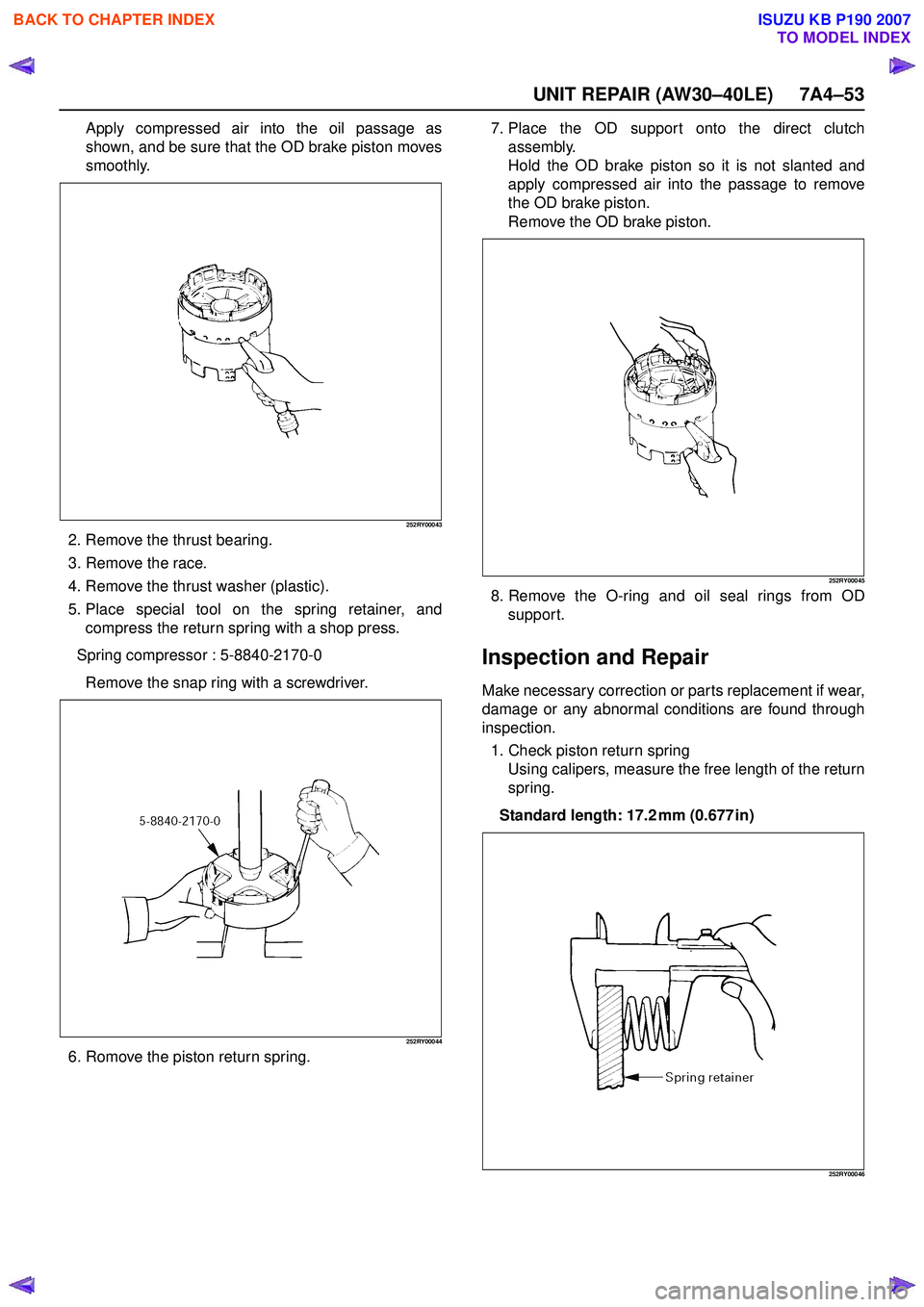
Apply compressed air into the oil passage as
shown, and be sure that the OD brake piston moves
smoothly.
252RY00043
2. Remove the thrust bearing.
3. Remove the race.
4. Remove the thrust washer (plastic).
5. Place special tool on the spring retainer, and compress the return spring with a shop press.
Spring compressor : 5-8840-2170-0 Remove the snap ring with a screwdriver.
252RY00044
6. Romove the piston return spring. 7. Place the OD support onto the direct clutch
assembly.
Hold the OD brake piston so it is not slanted and
apply compressed air into the passage to remove
the OD brake piston.
Remove the OD brake piston.
252RY00045
8. Remove the O-ring and oil seal rings from OD support.
Inspection and Repair
Make necessary correction or parts replacement if wear,
damage or any abnormal conditions are found through
inspection.
1. Check piston return spring Using calipers, measure the free length of the return
spring.
Standard length: 17.2 mm (0.677 in)
252RY00046
BACK TO CHAPTER INDEX
TO MODEL INDEX
ISUZU KB P190 2007
Page 4194 of 6020
UNIT REPAIR (AW30–40LE) 7A4–59
7. Place the direct clutch drum onto the OD support.Holding the direct clutch piston by hand, apply
compressed air to the OD support to remove the
direct clutch piston.
Remove the direct clutch piston from direct clutch
drum.
248RY00030
8. Remove two O-rings from piston.
Inspection and Repair
1. Check piston return spring. Using calipers, measure the free length of the return
spring.
Standard length: 21.3 mm (0.839 in)
247RY00034
2. Check discs. Using micrometer, measure the thickness of the
discs.
Minimum thickness: 2.04 mm (0.0803 in) If the thickness is less than the minimum, replace
the disc.
252RY00027
3. Check direct clutch piston. Check that check ball is free by shaking the piston.
Check that the valve does not leak by applying
low-pressure compressed air.
248RY00031
BACK TO CHAPTER INDEX
TO MODEL INDEX
ISUZU KB P190 2007
Page 4201 of 6020
7A4–66 UNIT REPAIR (AW30–40LE)
Before assembling new discs, soak them in ATF
for at least fifteen minutes.
248RY00045
4. Check piston return spring. Using calipers, measure the free length of the return
spring.
Standard length: 19.47 mm (0.7665 in)
247RY00034
Reassembly
1. Coat the assembled thrust bearing and race with petroleum jelly and install it onto the forward clutch
drum, with the race side facing downward.
Bearing and race (Reference)
248RY00044
2. Coat the three oil rings with ATF. Contract the oil seal rings as shown, and install
three oil seal rings onto the forward clutch drum.
NOTE: Do not spread the ring ends more than
necessary.
248RY00046
Inside diameter 33.7 mm (1.327 in)
Outside diameter 47.8 mm (1.882 in)
BACK TO CHAPTER INDEX
TO MODEL INDEX
ISUZU KB P190 2007
Page 4212 of 6020

UNIT REPAIR (AW30–40LE) 7A4–77
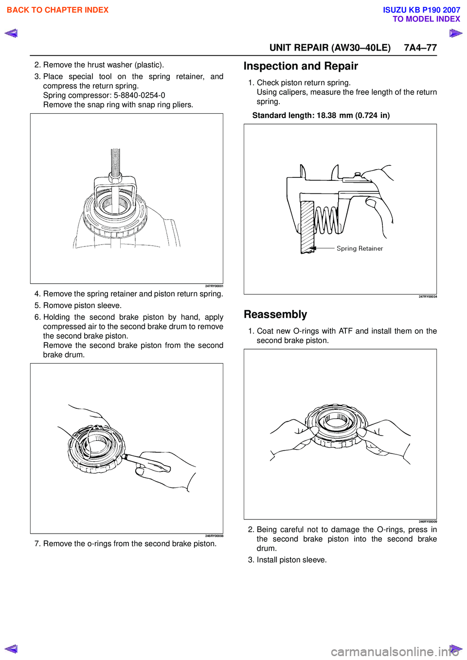
2. Remove the hrust washer (plastic).
3. Place special tool on the spring retainer, and compress the return spring.
Spring compressor: 5-8840-0254-0
Remove the snap ring with snap ring pliers.
247RY00001
4. Remove the spring retainer and piston return spring.
5. Romove piston sleeve.
6. Holding the second brake piston by hand, apply compressed air to the second brake drum to remove
the second brake piston.
Remove the second brake piston from the second
brake drum.
246RY00008
7. Remove the o-rings from the second brake piston.
Inspection and Repair
1. Check piston return spring. Using calipers, measure the free length of the return
spring.
Standard length: 18.38 mm (0.724 in)
247RY00034
Reassembly
1. Coat new O-rings with ATF and install them on the second brake piston.
246RY00009
2. Being careful not to damage the O-rings, press inthe second brake piston into the second brake
drum.
3. Install piston sleeve.
BACK TO CHAPTER INDEX
TO MODEL INDEX
ISUZU KB P190 2007
Page 4468 of 6020

7A3-14 ON-VEHICLE SERVICE (JR405E)
Install or Connect
1. Install the shift cable toward the inside of the cabin
from the bottom of the vehicle.
2. Push the shift cable into the select lever base.
3. Connect the shift cable to the select lever.
4. Fix the shift cable to the bracket.
Install the clip on the marking on the shift cable.
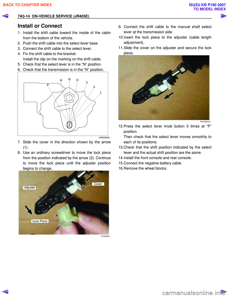
5. Check that the select lever is in the “N” position.
6. Check that the transmission is in the “N” position.
249R300002
7. Slide the cover in the direction shown by the arrow
(1).
8. Use an ordinary screwdriver to move the lock piece from the position indicated by the arrow (2). Continue
to move the lock piece until the adjuster position
begins to change.
P1010012
9. Connect the shift cable to the manual shaft select
lever at the transmission side.
10. Insert the lock piece to the adjuster (cable length adjustment).
11. Slide the cover on the adjuster and secure the lock piece.
P1010016-2
12. Press the select lever knob button 5 times at “P”position.
Then check that the select lever moves smoothly to each of its positions.
13. Check that the shift position indicated by the select lever and the actual shift position are the same.
14. Install the front console and rear console.
15. Connect the negative battery cable.
16. Remove the wheel blocks.
BACK TO CHAPTER INDEX
TO MODEL INDEX
ISUZU KB P190 2007
Page 4471 of 6020

ON-VEHICLE SERVICE (JR405E) 7A3-17
Remove or Disconnect
1. Block the wheels.
2. Disconnect the negative battery cable.
3. Drain the fluid.
Refer to “ATF CHANGE” in this section.
4. Remove the 19 bolts and oil pan.
5. Inspect the bottom of the oil pan and strainer netting for foreign material (clutch facing and metal
shavings).
If there is an excessive accumulation of foreign material, the oil strainer must be replaced.
Further inspection is required to determine the source of the foreign material.
6. Remove the harness assembly (including the oil temperature sensor).
7. Remove the 11 bolts and the solenoid fixing plate.
8. Remove the 6 solenoids and 3 oil pressure switches.
Inspect
Oil pressure switch
Apply compressed air (390 kPa/4.0 kgf/cm2/57 psi) to
the oil pressure switch to check the oil pressure switch
continuity between the connector and screw.
Replace the oil pressure switch if the result of inspection
is abnormal.
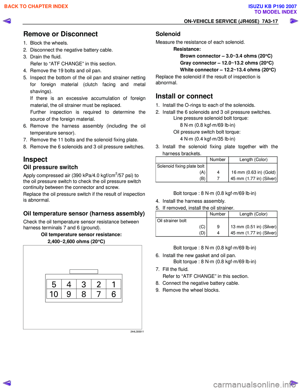
Oil temperature sensor (harness assembly)
Check the oil temperature sensor resistance between
harness terminals 7 and 6 (ground).
Oil temperature sensor resistance:
2,400~2,600 ohms (20 °
°°
°
C)
244L300011
Solenoid
Measure the resistance of each solenoid.
Resistance:
Brown connector – 3.0~3.4 ohms (20 °
°°
°
C)
Gray connector – 12.0~13.2 ohms (20 °
°°
°
C)
White connector – 12.2~13.4 ohms (20 °
°°
°
C)
Replace the solenoid if the result of inspection is
abnormal.
Install or connect
1. Install the O-rings to each of the solenoids.
2. Install the 6 solenoids and 3 oil pressure switches.
Line pressure solenoid bolt torque:
8 N·m (0.8 kgf·m/69 lb·in)
Oil pressure switch bolt torque:
4 N·m (0.4 kgf·m/35 lb·in)
3. Install the solenoid fixing plate together with the harness brackets.
Number Length (Color)
Solenoid fixing plate bolt
(A)
(B)
4
7
16 mm (0.63 in) (Gold)
45 mm (1.77 in) (Silver)
Bolt torque : 8 N·m (0.8 kgf·m/69 lb·in)
4. Install the harness assembly.
5. If removed, install the oil strainer.
Number Length (Color)
Oil strainer bolt
(C)
(D)
9
4
13 mm (0.51 in) (Silver)
45 mm (1.77 in) (Silver)
Bolt torque : 8 N·m (0.8 kgf·m/69 lb·in)
6. Install the new gasket and oil pan.
Bolt torque : 8 N·m (0.8 kgf·m/69 lb·in)
7. Fill the fluid.
Refer to “ATF CHANGE” in this section.
8. Connect the negative battery cable.
9. Remove the wheel blocks.
BACK TO CHAPTER INDEX
TO MODEL INDEX
ISUZU KB P190 2007
Page 4472 of 6020
7A3-18 ON-VEHICLE SERVICE (JR405E)
CONTROL VALVE ASSEMBLY
244L300001
Remove or Disconnect
1. Block the wheels.
2. Disconnect the negative battery cable.
3. Drain the fluid.
Refer to “ATF CHANGE” in this section.
4. Remove the 19 bolts and oil pan.
5. Inspect the bottom of the oil pan and strainer netting for foreign material (clutch facing and metal
shavings).
If there is an excessive accumulation of foreign material, the oil strainer must be replaced.
Further inspection is required to determine the source of the foreign material.
6. Disconnect the 2 harness connectors leading to the control valve.
7. Remove the 12 bolts and the control valve assembly.
Number of bolts Length
10 (A)
2 (B) 40 mm (1.57 in)
30 mm (1.18 in)
Note:
Take care not to disturb the manual valve (inside the
control valve assembly).
Do not allow the pin to fall free (the pin prevents the
valve from turning).
BACK TO CHAPTER INDEX
TO MODEL INDEX
ISUZU KB P190 2007