Page 4504 of 6020

UNIT REPAIR (JR405E) 7A4-27
Spring specifications
No. Valve nomenclature Free length
(mm / in) Outside
diameter
(mm / in) Linear
diameter
(mm / in) Number of
coils
14 Pressure relief 49.0 / 1.929 7.6 / 0.299 1.1 / 0.043 17.3
15 Pressure regulator 30.5 / 1.201 14.0 / 0.551 1.4 / 0.055 5.7
16 Low and reverse brake fail (A) 22.0 / 0.866 7.0 / 0.276 0.6 / 0.024 10.0
17 Fail 23.0 / 0.906 11.0 / 0.433 0.5 / 0.020 13.2
18 Low and reverse brake amp 19.5 / 0.768 7.9 / 0.311 0.5 / 0.020 6.9
19 2 – 4 brake fail (A) 24.8 / 0.976 8.5 / 0.335 0.9 / 0.035 7.8
20 Low clutch amp (B) 26.0 / 1.024 11.0 / 0.433 0.5 / 0.020 6.9
21
Torque converter relief More than 47.2
/ 1.858 9.2 / 0.362 1.6 / 0.063 20.2
22 2 – 4 brake solenoid accumulator 31.4 / 1.236 9.8 / 0.386 1.3 / 0.051 9.3
23 High clutch accumulator
51.0 / 2.008 6.5 / 0.256 0.8 / 0.031 23.5
Oil pressure switch
Apply compressed air (390 kPa/4.0 kgf/cm2/57 psi) to the oil
pressure switch to check the oil pressure switch continuity
between the connector and screw.
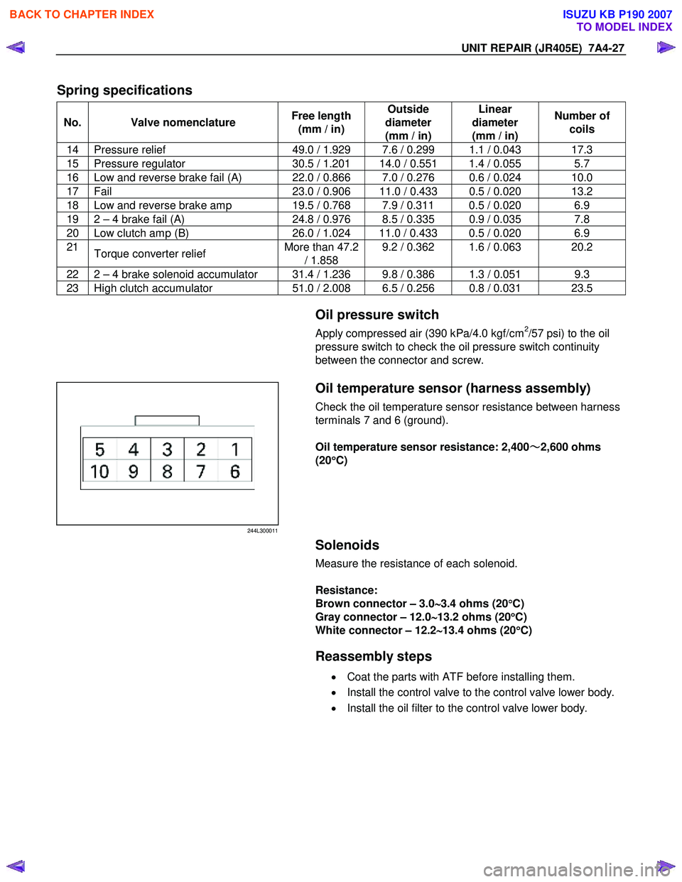
244L300011
Oil temperature sensor (harness assembly)
Check the oil temperature sensor resistance between harness
terminals 7 and 6 (ground).
Oil temperature sensor resistance: 2,400 ~
~~
~
2,600 ohms
(20 °
°°
°
C)
Solenoids
Measure the resistance of each solenoid.
Resistance:
Brown connector – 3.0 ∼
∼∼
∼
3.4 ohms (20 °
°°
°
C)
Gray connector – 12.0 ∼
∼∼
∼
13.2 ohms (20 °
°°
°
C)
White connector – 12.2 ∼
∼∼
∼
13.4 ohms (20 °
°°
°
C)
Reassembly steps
• Coat the parts with ATF before installing them.
• Install the control valve to the control valve lower body.
• Install the oil filter to the control valve lower body.
BACK TO CHAPTER INDEX
TO MODEL INDEX
ISUZU KB P190 2007
Page 4512 of 6020

UNIT REPAIR (JR405E) 7A4-35
Return springs • Check the number of effective return spring coils.
If the number is less than the specified minimum, the
return spring must be replaced.
Effective return spring coils (standard): 10.2
• Measure the return spring outside diameter, free length,
and linear diameter.
If any of the measured values exceed the specified limit,
the return spring must be replaced.
Return spring measurements (standard):
Outside diameter – 8.0 mm (0.315 in)
Free length – 27.1 mm (1.067 in)
Linear diameter – 1.1 mm (0.043 in)
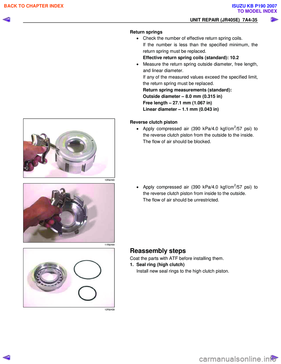
10R&H40
Reverse clutch piston
• Apply compressed air (390 kPa/4.0 kgf/cm
2/57 psi) to
the reverse clutch piston from the outside to the inside.
The flow of air should be blocked.
11R&H44
•
Apply compressed air (390 kPa/4.0 kgf/cm2/57 psi) to
the reverse clutch piston from inside to the outside.
The flow of air should be unrestricted.
12R&H39
Reassembly steps
Coat the parts with ATF before installing them.
1. Seal ring (high clutch)
Install new seal rings to the high clutch piston.
BACK TO CHAPTER INDEX
TO MODEL INDEX
ISUZU KB P190 2007
Page 4523 of 6020

7A4-46 UNIT REPAIR (JR405E)
18C&L-SUB28
19.Low one-way clutch
Remove the low one-way clutch.
19C&L-SUB29
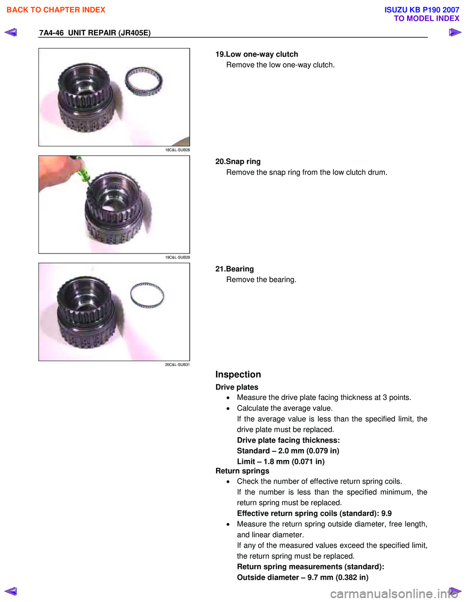
20.Snap ring
Remove the snap ring from the low clutch drum.
20C&L-SUB31
21.Bearing
Remove the bearing.
Inspection
Drive plates
• Measure the drive plate facing thickness at 3 points.
• Calculate the average value.
If the average value is less than the specified limit, the
drive plate must be replaced.
Drive plate facing thickness:
Standard – 2.0 mm (0.079 in)
Limit – 1.8 mm (0.071 in)
Return springs
• Check the number of effective return spring coils.
If the number is less than the specified minimum, the
return spring must be replaced.
Effective return spring coils (standard): 9.9
• Measure the return spring outside diameter, free length,
and linear diameter.
If any of the measured values exceed the specified limit,
the return spring must be replaced.
Return spring measurements (standard):
Outside diameter – 9.7 mm (0.382 in)
BACK TO CHAPTER INDEX
TO MODEL INDEX
ISUZU KB P190 2007
Page 4524 of 6020
UNIT REPAIR (JR405E) 7A4-47
Free length – 36.4 mm (1.433 in)
Linear diameter – 1.2 mm (0.047 in)
21C&L-SUB31
Reassembly steps
Coat the parts with ATF before installing them.
1. Bearing
Install the bearing into the low clutch drum.
22C&L-SUB30
2. Snap ring
Install the snap ring to the low clutch drum.
23C&L-SUB28
3. Low one-way clutch
Install the low one-way clutch to the low clutch drum.
24C&L-SUB33
NOTE:
The flanged side of the low one-way clutch must face the
outside.
BACK TO CHAPTER INDEX
TO MODEL INDEX
ISUZU KB P190 2007
Page 4534 of 6020

UNIT REPAIR (JR405E) 7A4-57
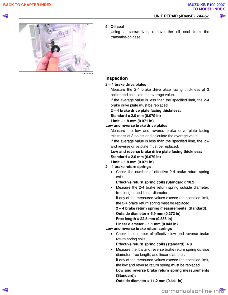
11CASE-AY01
5. Oil seal
Using a screwdriver, remove the oil seal from the
transmission case.
Inspection
2 – 4 brake drive plates
Measure the 2-4 brake drive plate facing thickness at 3
points and calculate the average value.
If the average value is less than the specified limit, the 2-4
brake drive plate must be replaced.
2 – 4 brake drive plate facing thickness:
Standard = 2.0 mm (0.079 in)
Limit = 1.8 mm (0.071 in)
Low and reverse brake drive plates
Measure the low and reverse brake drive plate facing
thickness at 3 points and calculate the average value.
If the average value is less than the specified limit, the lo
w
and reverse drive plate must be replaced.
Low and reverse brake drive plate facing thickness:
Standard = 2.0 mm (0.079 in)
Limit = 1.8 mm (0.071 in)
2 – 4 brake return springs
• Check the number of effective 2-4 brake return spring
coils.
Effective return spring coils (Standard): 10.2
• Measure the 2-4 brake return spring outside diameter,
free length, and linear diameter.
If any of the measured values exceed the specified limit,
the 2-4 brake return spring must be replaced.
2 – 4 brake return spring measurements (Standard):
Outside diameter = 6.9 mm (0.272 in)
Free length = 22.5 mm (0.886 in)
Linear diameter = 1.1 mm (0.043 in)
Low and reverse brake return springs
• Check the number of effective low and reverse brake
return spring coils.
Effective return spring coils (standard): 4.8
• Measure the low and reverse brake return spring outside
diameter, free length, and linear diameter.
If any of the measured values exceed the specified limit,
the low and reverse return spring must be replaced.
Low and reverse brake return spring measurements
(Standard):
Outside diameter = 11.2 mm (0.441 in)
BACK TO CHAPTER INDEX
TO MODEL INDEX
ISUZU KB P190 2007
Page 4535 of 6020
7A4-58 UNIT REPAIR (JR405E)
Free length = 22.3 mm (0.878 in)
Linear diameter = 1.1 mm (0.043 in)
12CASE-AY06
Reassembly steps
1. Oil seal, manual shaft, and manual plate
• Use the oil seal installer to force the manual plate oil
seal into place.
Oil seal installer: 5-8840-2758-0
14CASE-AY21
•
Install the manual shaft together with the manual plate.
15CASE-AY26
•
Drive the spring pin into the transmission case.
16CASE-AY37
2. Parking rod
• Rotate the manual plate while installing the parking rod.
BACK TO CHAPTER INDEX
TO MODEL INDEX
ISUZU KB P190 2007
Page 4557 of 6020
7A4-80 UNIT REPAIR (JR405E)
43ASSY119
20.Control valve assembly
•
Align the manual valve and the manual plate of the
transmission case.
• Install the control valve assembly and tighten the 12
fixing bolts to the specified torque.
Number of bolts Length Color
10 (A) 40 mm (1.57 in) Gold
2 (B) 30 mm (1.18 in) Gold
44ASSY121
Torque: 8 N ⋅
⋅⋅
⋅
m (0.8 kgf ⋅
⋅⋅
⋅
m/69 Ib ⋅
⋅⋅
⋅
in)
45CV29
•
Connect the harness assembly and control valve
assembly connectors.
BACK TO CHAPTER INDEX
TO MODEL INDEX
ISUZU KB P190 2007
Page 4560 of 6020

UNIT REPAIR (JR405E) 7A4-83
SERVICE STANDARD
Name BESCO ATF III ATF
Quantity L (US gal/Imp gal) 9.2 – 9.6 (2.43-2.54/2.02-2.11)
Seal ring clearance mm (in) 0.10 – 0.25 (0.0039 – 0.0098)
Housing and inner rotor side clearance mm (in) 0.02 – 0.04 (0.0008 – 0.0016)
Oil pump
Outer rotor and crescent clearance mm (in) 0.02 – 0.15 (0.0008 – 0.0059)
Number of drive plates / driven plates 7/7
Standard mm (in) 2.0 (0.079)Drive plate facing thickness
Limit mm (in) 1.8 (0.071)
Retaining plate and snap ring clearance mm (in) 0.9 – 1.3 (0.035 – 0.051)
3.8 (0.150)
4.0 (0.157)
4.2 (0.165)
4.4 (0.173)
4.6 (0.181)
Available low clutch retaining plate thickness mm (in)
4.8 (0.189)
Number of coils 9.9
Outside diameter mm (in) 9.7 (0.382)
Free length mm (in) 36.4 (1.433)
Low clutch
Return spring Linear diameter mm (in) 1.2 (0.047)
Number of drive plates / driven plates 5/5
Standard mm (in) 2.0 (0.079)Drive plate facing thickness
Limit mm (in) 1.8 (0.071)
Retaining plate and snap ring clearance mm (in) 1.2 – 1.6 (0.047 – 0.063)
4.6 (0.181)
4.8 (0.189)
5.0 (0.197)
5.2 (0.205)
Available high clutch retaining plate thickness mm (in)
5.4 (0.213)
Number of coils 10.2
Outside diameter mm (in) 8.0 (0.315)
Free length mm (in) 27.1 (1.067)
High clutch
Return spring Linear diameter mm (in) 1.1 (0.043)
Number of drive plates / driven plates 2/2
Standard mm (in) 2.0 (0.079)Drive plate facing thickness
Limit mm (in) 1.8 (0.071)
Retaining plate and snap ring clearance mm (in) 0.6 – 0.9 (0.024 – 0.035)
4.8 (0.189)
5.0 (0.197)
5.2 (0.205)
Reverse clutch
Available reverse clutch retaining plate thickness mm (in) 5.4 (0.213)
Low one-way
clutch Seal ring clearance mm (in) 0.10 – 0.25 (0.0039 – 0.0098)
Number of drive plates / driven plates
6/6
Standard mm (in) 2.0 (0.079)Drive plate facing thickness
Limit mm (in) 1.8 (0.071)
Retaining plate and snap ring clearance mm (in) 0.7 – 1.1 (0.028 – 0.043)
5.2 (0.205)
5.4 (0.213)
5.6 (0.220)
5.8 (0.228)
Low & reverse
brake
Available low & reverse brake retaining plate
thickness mm (in)
6.0 (0.236)
BACK TO CHAPTER INDEX
TO MODEL INDEX
ISUZU KB P190 2007