2007 ISUZU KB P190 length
[x] Cancel search: lengthPage 2398 of 6020
6E–228 ENGINE DRIVEABILITY AND EMISSIONS
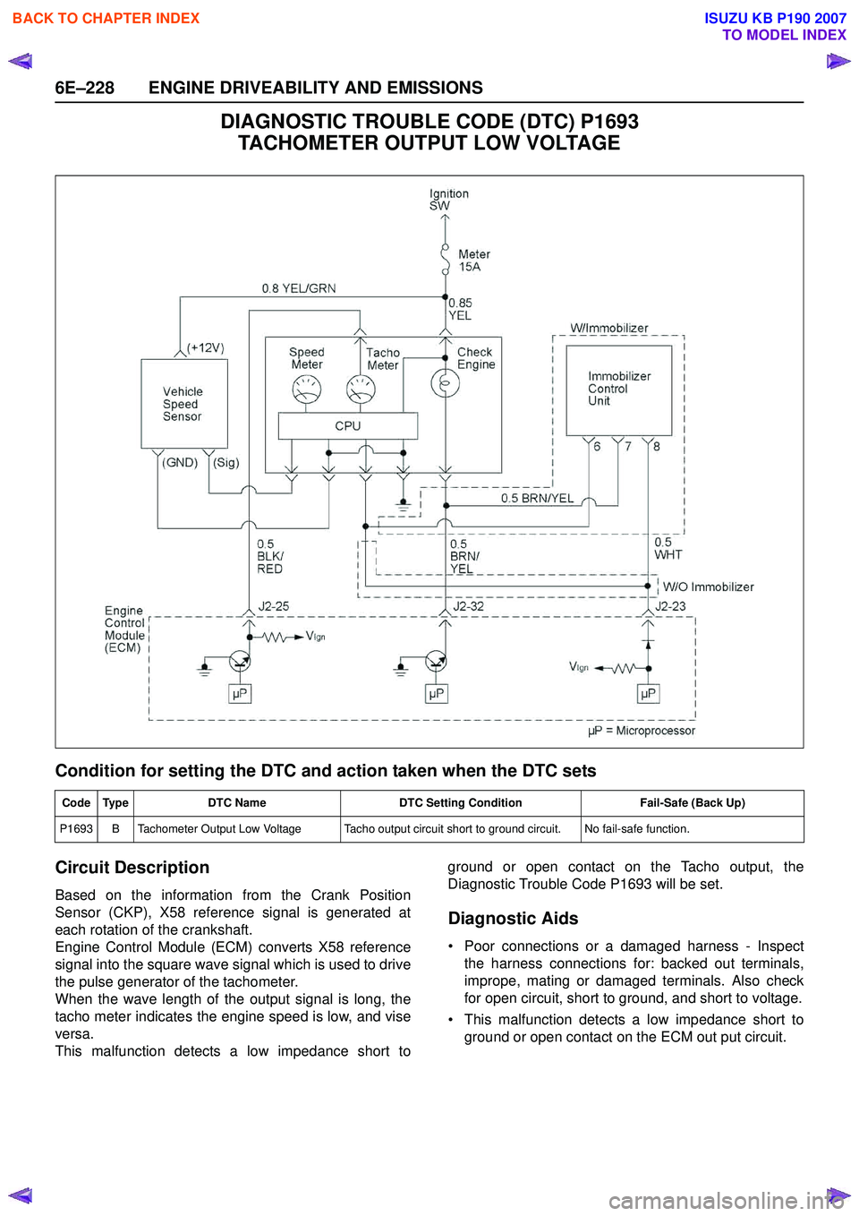
DIAGNOSTIC TROUBLE CODE (DTC) P1693 TACHOMETER OUTPUT LOW VOLTAGE
Condition for setting the DTC and action taken when the DTC sets
Circuit Description
Based on the information from the Crank Position
Sensor (CKP), X58 reference signal is generated at
each rotation of the crankshaft.
Engine Control Module (ECM) converts X58 reference
signal into the square wave signal which is used to drive
the pulse generator of the tachometer.
When the wave length of the output signal is long, the
tacho meter indicates the engine speed is low, and vise
versa.
This malfunction detects a low impedance short to ground or open contact on the Tacho output, the
Diagnostic Trouble Code P1693 will be set.
Diagnostic Aids
• Poor connections or a damaged harness - Inspect the harness connections for: backed out terminals,
imprope, mating or damaged terminals. Also check
for open circuit, short to ground, and short to voltage.
• This malfunction detects a low impedance short to ground or open contact on the ECM out put circuit.
Code Type DTC Name DTC Setting Condition Fail-Safe (Back Up)
P1693 B Tachometer Output Low Voltage Tacho output circuit short to ground circuit. No fail-safe function.
BACK TO CHAPTER INDEX
TO MODEL INDEX
ISUZU KB P190 2007
Page 2487 of 6020
Engine Mechanical – V6 Page 6A1–8
1 General Information
The HFV6 engine features a closed vee, deep skirt die cast aluminium cylinder block with cast iron cylinder liners,
internally balanced crankcase, full length water jackets and six bolt main bearing caps.
The cylinders are arranged in two banks of three with a 60 degree included angle between the two banks.
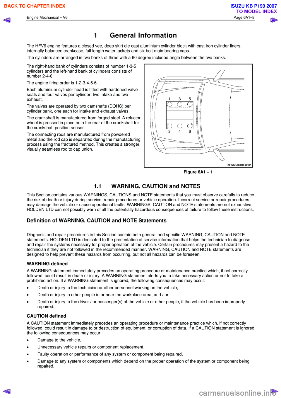
The right-hand bank of cylinders consists of number 1-3-5
cylinders and the left-hand bank of cylinders consists of
number 2-4-6.
The engine firing order is 1-2-3-4-5-6.
Each aluminium cylinder head is fitted with hardened valve
seats and four valves per cylinder: two intake and two
exhaust.
The valves are operated by two camshafts (DOHC) per
cylinder bank, one each for intake and exhaust valves.
The crankshaft is manufactured from forged steel. A reluctor
wheel is pressed in place onto the rear of the crankshaft for
the crankshaft position sensor.
The connecting rods are manufactured from powdered
metal and the rod cap is separated during the manufacturing
process using the fractured method. This creates a stronger,
visually seamless rod to cap union.
Figure 6A1 – 1
1.1 WARNING, CAUTION and NOTES
This Section contains various W ARNINGS, CAUTIONS and NOTE statements that you must observe carefully to reduce
the risk of death or injury during service, repair procedures or vehicle operation. Incorrect service or repair procedures
may damage the vehicle or cause operational faults. W ARNINGS, CAUTION and NOTE statements are not exhaustive.
HOLDEN LTD can not possibly warn of all the potentially hazardous consequences of failure to follow these instructions.
Definition of WARNING, CAUTION and NOTE Statements
Diagnosis and repair procedures in this Section contain both general and specific W ARNING, CAUTION and NOTE
statements. HOLDEN LTD is dedicated to the presentation of service information that helps the technician to diagnose
and repair the systems necessary for proper operation of the vehicle. Certain procedures may present a hazard to the
technician if they are not followed in the recommended manner. W ARNING, CAUTION and NOTE statements are
designed to help prevent these hazards from occurring, but not all hazards can be foreseen.
WARNING defined
A W ARNING statement immediately precedes an operating procedure or maintenance practice which, if not correctly
followed, could result in death or injury. A W ARNING statement alerts you to take necessary action or not to take a
prohibited action. If a W ARNING statement is ignored, the following consequences may occur:
• Death or injury to the technician or other personnel working on the vehicle,
• Death or injury to other people in or near the workplace area, and / or
• Death or injury to the driver / or passenger(s) of the vehicle or other people, if the vehicle has been improperly
repaired.
CAUTION defined
A CAUTION statement immediately precedes an operating procedure or maintenance practice which, if not correctly
followed, could result in damage to or destruction of equipment, or corruption of data. If a CAUTION statement is ignored,
the following consequences may occur:
• Damage to the vehicle,
• Unnecessary vehicle repairs or component replacement,
• Faulty operation or performance of any system or component being repaired,
• Damage to any system or components which depend on the proper operation of the system or component being
repaired,
BACK TO CHAPTER INDEX
TO MODEL INDEX
ISUZU KB P190 2007
Page 2525 of 6020
Engine Mechanical – V6 Page 6A1–46
7 Misalignment of the pulleys may be caused by one of the following:
• Incorrect mounting of an accessory drive component,
• Incorrect installation of an accessory drive pulley or,
• Bent or damaged pulley.
Test for a misaligned pulley using a straight edge in the pulley grooves across 2 or 3 pulleys. If a misaligned pulley is found, refer to the relevant component service information for the correct installation and removal procedures.
8 This test is to confirm the pulleys are the correct diameter and/or width. Using a known good vehicle, compare the pulley sizes.
Diagnostic Table
Step Action Yes No
1 Did you review the information provided in 2.2 Symptoms, and
perform the required inspections. Go to Step 2 Go to 2.2
Symptoms
2 Confirm the customer complaint. Is there a squealing noise? Go to Step 3 Refer to Diagnostic
Aids in this Section
3 1 Remove the drive belt, refer to 3.5 Accessory Drive Belt.
2 Operate the engine for no more than 40 seconds.
Does the squealing noise still exist? Accessory drive
system OK.
Go to 2.2
Symptoms, and restart the
diagnosis of the noise Go to Step 4
4 Inspect the accessory drive components for a seized bearing and
general malfunctions.
Did you find and correct any seized bearings or general malfunctions
in the accessory drive system? Go to Step 9 Go to Step 5
5 Test the accessory drive belt tensioner for correct operation, refer to
Accessory Drive Belt Tensioner Diagnosis.
Did you find and repair any problems with the tensioner? Go to Step 9 Go to Step 6
6 Inspect the accessory drive belt is the correct length, refer to 3.5
Accessory Drive Belt.
Did you find and repair any problems with the drive belt length? Go to Step 9 Go to Step 7
7 Inspect the accessory drive pulleys for misalignment.
Did you find and correct any misaligned accessory drive pulleys? Go to Step 9 Go to Step 8
8 Check the accessory drive pulleys are the correct size. Did you find and replace any incorrect pulleys? Go to Step 9 Refer to Diagnostic
Aids in this Section
9 Reinstall the accessory drive belt and operate the system to confirm
the repair.
Did you correct the squeal noise? Accessory drive
system OK Go to 2.2
Symptoms, and restart the diagnosis
Drive Belt Whine
Definition
Accessory drive belt whine can be defined as a high-pitched continuous noise that is most likely to be caused by a failed
bearing in one of the accessory drive components.
Diagnostic Aids
The drive belts themselves will not cause a whine. If the noise is intermittent, confirm the accessory drive components by
varying their loads, making sure they are operated to their maximum capacity. An overcharged A/C system, restrictions
in the power steering pressure circuit or a faulty generator or coolant pump are likely causes of accessory drive belt
whine.
Test Description
The numbers below refer to steps in the diagnostic table.
BACK TO CHAPTER INDEX
TO MODEL INDEX
ISUZU KB P190 2007
Page 2529 of 6020

Engine Mechanical – V6 Page 6A1–50
Diagnostic Table
Step Action Yes No
1 Did you review the information provided in 2.2 Symptoms, and
perform the required inspections. Go to Step 2 Go to 2.2
Symptoms
2 Confirm the customer complaint. Is there a rumbling noise? Go to Step 3 Refer to Diagnostic
Aids in this Section
3 1 Remove the drive belt, refer to 3.5 Accessory Drive Belt.
2 Operate the engine for no more than 40 seconds.
Does the vibration noise still exist? Accessory drive
system OK.
Go to 4.2
Symptoms, and
restart the diagnosis Go to Step 4
4 Inspect the accessory drive belt for damage, wear, debris build-up or
sections of missing ribs.
Did you find any damage, wear, debris build-up or missing ribs? Go to Step 5 Go to Step 6
5 Install a new accessory drive belt, refer to 3.5 Accessory Drive Belt.
Did you replace the accessory drive belt? Go to Step 10 —
6 Inspect for incorrect, loose, missing or damaged fasteners. Did you find any incorrect, loose, missing or damaged fasteners? Go to Step 7 Go to Step 8
7 Tighten any loose fasteners to the correct torque specification, refer to
6 Torque W rench Specifications.
Replace any incorrect or missing fasteners.
Did you complete the repairs? Go to Step 10 —
8 Inspect the coolant pump for a bent shaft, refer to 6B1 Engine Cooling – V6.
Did you find and repair a bent coolant pump shaft? Go to Step 10 Go to Step 9
9 Inspect for bent, cracked or damaged accessory drive component mounting brackets.
Did you find and repair any bent brackets? Go to Step 10 Refer to Diagnostic
Aids in this Section
10 If required, reinstall the accessory drive belt and operate the system to
confirm the repair.
Did you correct the vibration? Accessory drive
system OK Refer to Diagnostic
Aids in this Section
Drive Belt Falls Off
Definition
The drive belt falls off during normal operation or does not ride correctly on the accessory drive pulleys.
Diagnostic Aids
If the accessory drive belt repeatedly falls off the drive pulleys, this is most likely due to pulley misalignment.
An extra load that is quickly applied and released by an accessory drive component (e.g. A/C compressor) may cause
the accessory drive belt to fall off. In this circumstance, confirm the fault by operating the accessory drive components in
turn, noting which one caused the belt to fall off.
Lack of drive belt tension may also cause the belt to fall off the pulleys. Low drive belt tension could be caused by one of
the following:
• an incorrect drive belt length,
• a faulty drive belt tensioner, or
• a stretched or faulty drive belt.
Test Description
The numbers below refer to steps in the diagnostic table.
2 Confirms the condition of the drive belt. Damage may have occurred to the drive belt when it first fell off or it may have been damaged which caused the belt to fall off.
4 Misalignment of the pulleys may be caused by:
BACK TO CHAPTER INDEX
TO MODEL INDEX
ISUZU KB P190 2007
Page 2666 of 6020
Engine Mechanical – V6 Page 6A1–187
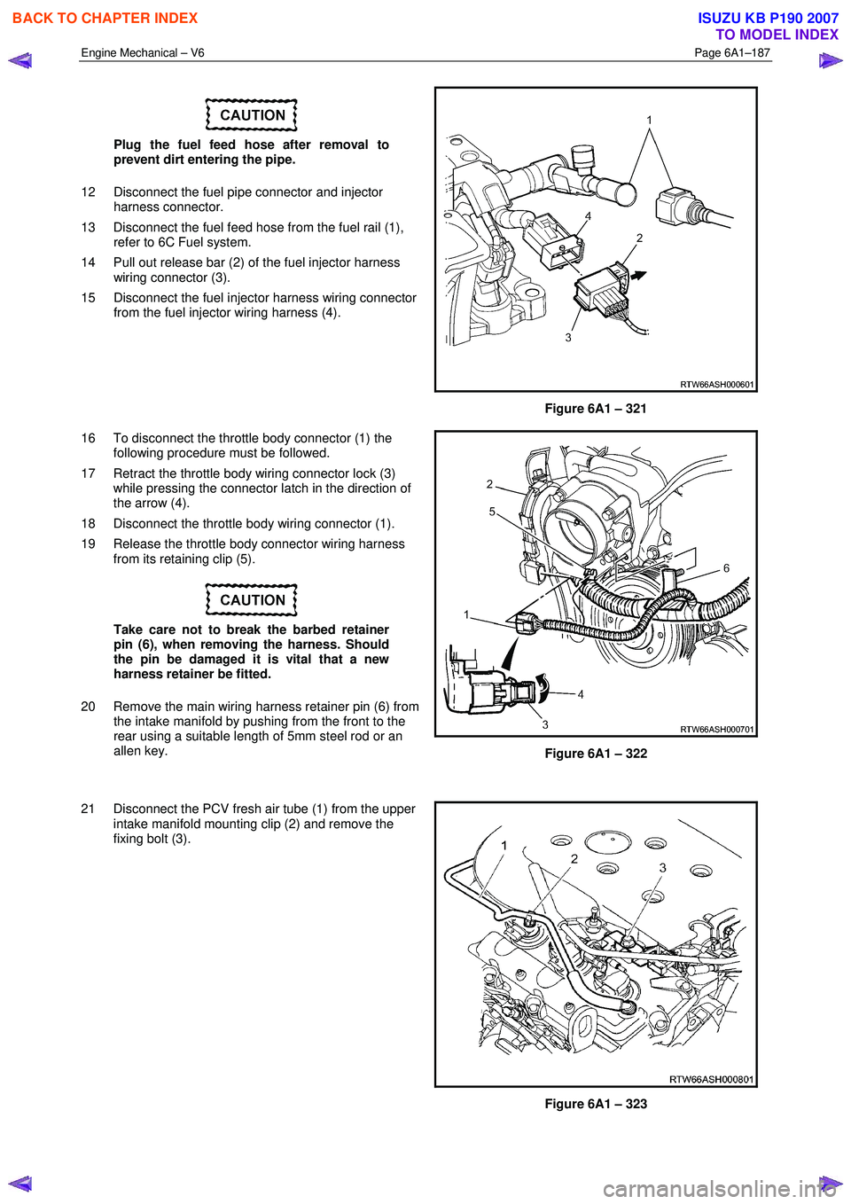
Plug the fuel feed hose after removal to
prevent dirt entering the pipe.
12 Disconnect the fuel pipe connector and injector harness connector.
13 Disconnect the fuel feed hose from the fuel rail (1), refer to 6C Fuel system.
14 Pull out release bar (2) of the fuel injector harness wiring connector (3).
15 Disconnect the fuel injector harness wiring connector from the fuel injector wiring harness (4).
Figure 6A1 – 321
16 To disconnect the throttle body connector (1) the following procedure must be followed.
17 Retract the throttle body wiring connector lock (3) while pressing the connector latch in the direction of
the arrow (4).
18 Disconnect the throttle body wiring connector (1).
19 Release the throttle body connector wiring harness from its retaining clip (5).
Take care not to break the barbed retainer
pin (6), when removing the harness. Should
the pin be damaged it is vital that a new
harness retainer be fitted.
20 Remove the main wiring harness retainer pin (6) from the intake manifold by pushing from the front to the
rear using a suitable length of 5mm steel rod or an
allen key.
Figure 6A1 – 322
21 Disconnect the PCV fresh air tube (1) from the upper intake manifold mounting clip (2) and remove the
fixing bolt (3).
Figure 6A1 – 323
BACK TO CHAPTER INDEX
TO MODEL INDEX
ISUZU KB P190 2007
Page 2700 of 6020
Engine Mechanical – V6 Page 6A1–221
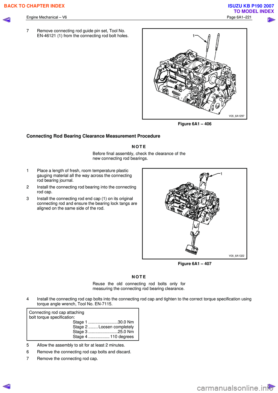
7 Remove connecting rod guide pin set, Tool No.
EN-46121 (1) from the connecting rod bolt holes.
Figure 6A1 – 406
Connecting Rod Bearing Clearance Measurement Procedure
NOTE
Before final assembly, check the clearance of the
new connecting rod bearings.
1 Place a length of fresh, room temperature plastic gauging material all the way across the connecting
rod bearing journal.
2 Install the connecting rod bearing into the connecting rod cap.
3 Install the connecting rod end cap (1) on its original connecting rod and ensure the bearing lock tangs are
aligned on the same side of the rod.
Figure 6A1 – 407
NOTE
Reuse the old connecting rod bolts only for
measuring the connecting rod bearing clearance.
4 Install the connecting rod cap bolts into the connecting rod cap and tighten to the correct torque specification using torque angle wrench, Tool No. EN-7115.
Connecting rod cap attaching
bolt torque specification:
Stage 1 .........................30.0 Nm
Stage 2 ........ Loosen completely
Stage 3 .........................25.0 Nm
Stage 4 .................. 110 degrees
5 Allow the assembly to sit for at least 2 minutes.
6 Remove the connecting rod cap bolts and discard.
7 Remove the connecting rod cap.
BACK TO CHAPTER INDEX
TO MODEL INDEX
ISUZU KB P190 2007
Page 2710 of 6020
Engine Mechanical – V6 Page 6A1–231
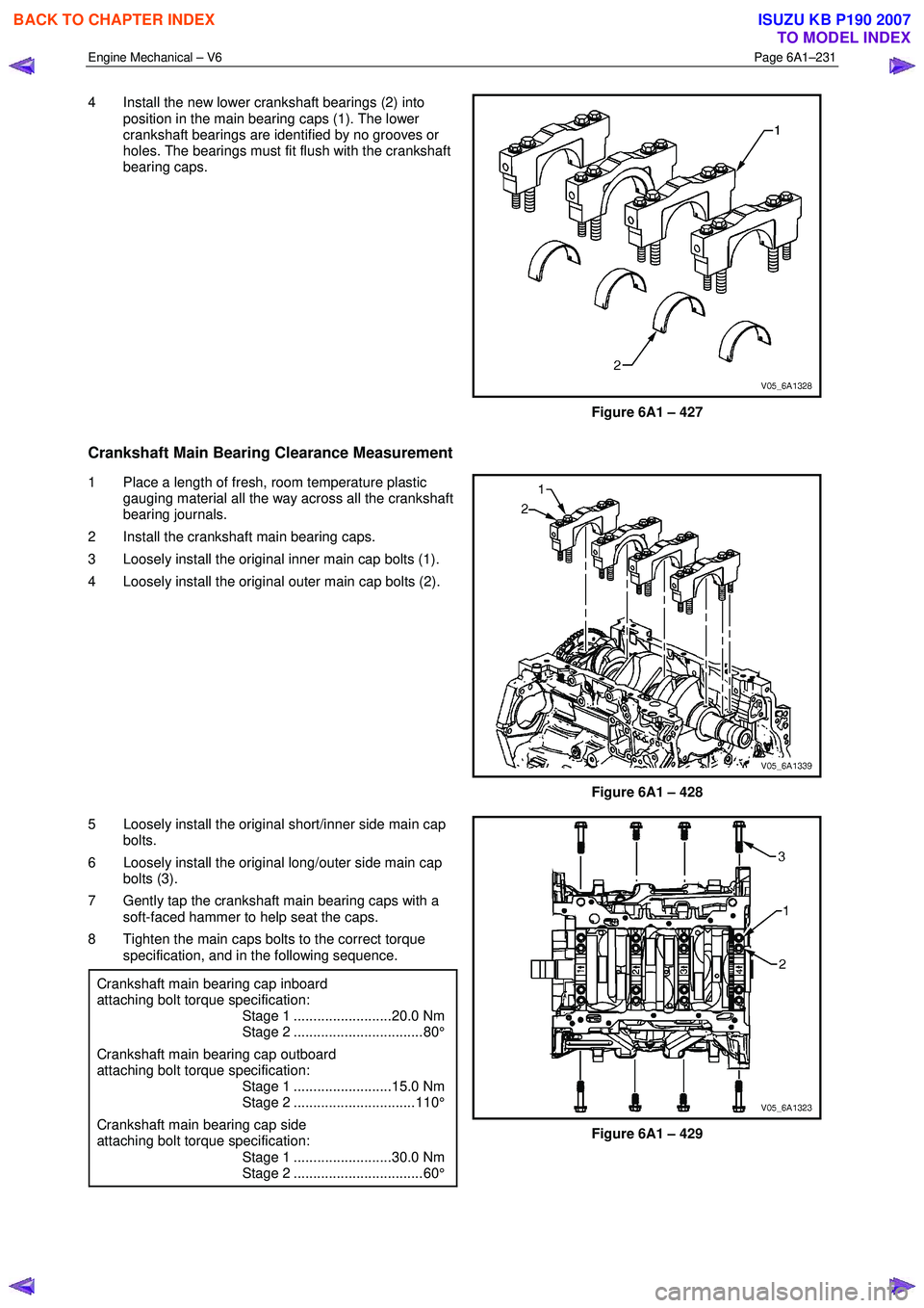
4 Install the new lower crankshaft bearings (2) into
position in the main bearing caps (1). The lower
crankshaft bearings are identified by no grooves or
holes. The bearings must fit flush with the crankshaft
bearing caps.
Figure 6A1 – 427
Crankshaft Main Bearing Clearance Measurement
1 Place a length of fresh, room temperature plastic gauging material all the way across all the crankshaft
bearing journals.
2 Install the crankshaft main bearing caps.
3 Loosely install the original inner main cap bolts (1).
4 Loosely install the original outer main cap bolts (2).
Figure 6A1 – 428
5 Loosely install the original short/inner side main cap bolts.
6 Loosely install the original long/outer side main cap bolts (3).
7 Gently tap the crankshaft main bearing caps with a soft-faced hammer to help seat the caps.
8 Tighten the main caps bolts to the correct torque specification, and in the following sequence.
Crankshaft main bearing cap inboard
attaching bolt torque specification:
Stage 1 .........................20.0 Nm
Stage 2 ................................. 80°
Crankshaft main bearing cap outboard
attaching bolt torque specification:
Stage 1 .........................15.0 Nm
Stage 2 ............................... 110°
Crankshaft main bearing cap side
attaching bolt torque specification:
Stage 1 .........................30.0 Nm
Stage 2 ................................. 60°
Figure 6A1 – 429
BACK TO CHAPTER INDEX
TO MODEL INDEX
ISUZU KB P190 2007
Page 2726 of 6020
Engine Mechanical – V6 Page 6A1–247
NOTE
A correctly counter bored hole will show a slight
burnishing on the surface of the base material
for 360 degrees around the drilled hole.
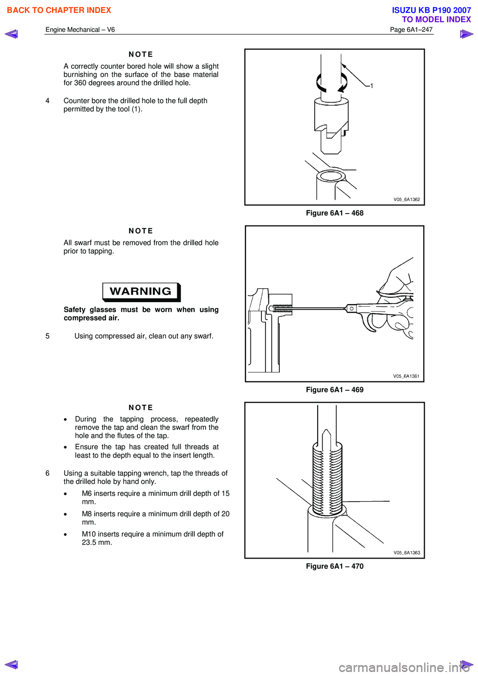
4 Counter bore the drilled hole to the full depth permitted by the tool (1).
Figure 6A1 – 468
NOTE
All swarf must be removed from the drilled hole
prior to tapping.
Safety glasses must be worn when using
compressed air.
5 Using compressed air, clean out any swarf.
Figure 6A1 – 469
NOTE
• During the tapping process, repeatedly
remove the tap and clean the swarf from the
hole and the flutes of the tap.
• Ensure the tap has created full threads at
least to the depth equal to the insert length.
6 Using a suitable tapping wrench, tap the threads of the drilled hole by hand only.
• M6 inserts require a minimum drill depth of 15
mm.
• M8 inserts require a minimum drill depth of 20
mm.
• M10 inserts require a minimum drill depth of
23.5 mm.
Figure 6A1 – 470
BACK TO CHAPTER INDEX
TO MODEL INDEX
ISUZU KB P190 2007