2007 ISUZU KB P190 length
[x] Cancel search: lengthPage 1073 of 6020
Engine Control System (4JH1) 6E-39
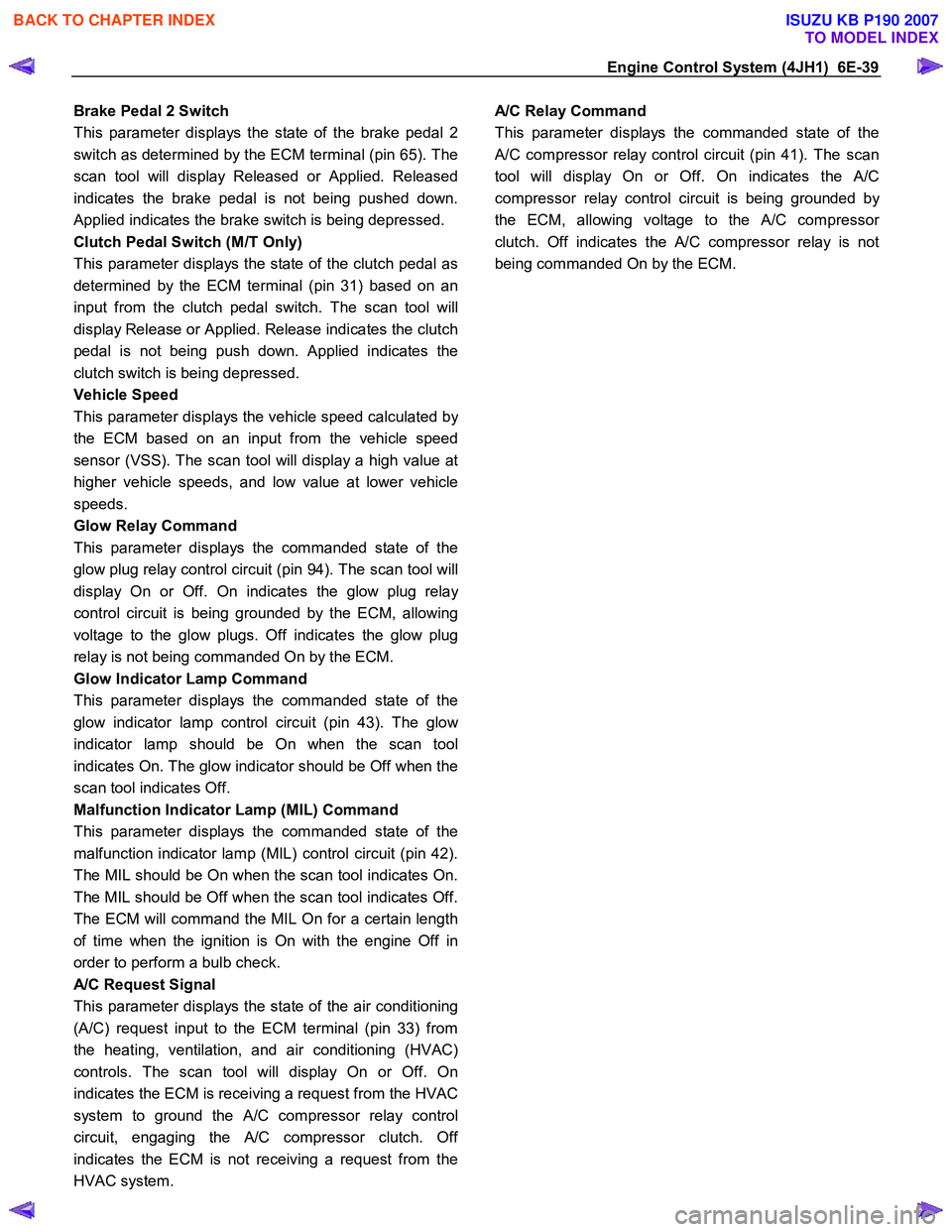
Brake Pedal 2 Switch
This parameter displays the state of the brake pedal 2
switch as determined by the ECM terminal (pin 65). The
scan tool will display Released or Applied. Released
indicates the brake pedal is not being pushed down.
Applied indicates the brake switch is being depressed.
Clutch Pedal Switch (M/T Only)
This parameter displays the state of the clutch pedal as
determined by the ECM terminal (pin 31) based on an
input from the clutch pedal switch. The scan tool will
display Release or Applied. Release indicates the clutch
pedal is not being push down. Applied indicates the
clutch switch is being depressed.
Vehicle Speed
This parameter displays the vehicle speed calculated b
y
the ECM based on an input from the vehicle speed
sensor (VSS). The scan tool will display a high value at
higher vehicle speeds, and low value at lower vehicle
speeds.
Glow Relay Command
This parameter displays the commanded state of the
glow plug relay control circuit (pin 94). The scan tool will
display On or Off. On indicates the glow plug rela
y
control circuit is being grounded by the ECM, allowing
voltage to the glow plugs. Off indicates the glow plug
relay is not being commanded On by the ECM.
Glow Indicator Lamp Command
This parameter displays the commanded state of the
glow indicator lamp control circuit (pin 43). The glo
w
indicator lamp should be On when the scan tool
indicates On. The glow indicator should be Off when the
scan tool indicates Off.
Malfunction Indicator Lamp (MIL) Command
This parameter displays the commanded state of the
malfunction indicator lamp (MIL) control circuit (pin 42).
The MIL should be On when the scan tool indicates On.
The MIL should be Off when the scan tool indicates Off.
The ECM will command the MIL On for a certain length
of time when the ignition is On with the engine Off in
order to perform a bulb check.
A/C Request Signal
This parameter displays the state of the air conditioning
(A/C) request input to the ECM terminal (pin 33) from
the heating, ventilation, and air conditioning (HVAC)
controls. The scan tool will display On or Off. On
indicates the ECM is receiving a request from the HVAC
system to ground the A/C compressor relay control
circuit, engaging the
A/C compressor clutch. Off
indicates the ECM is not receiving a request from the
HVAC system.
A/C Relay Command
This parameter displays the commanded state of the
A/C compressor relay control circuit (pin 41). The scan
tool will display On or Off. On indicates the
A/C
compressor relay control circuit is being grounded b
y
the ECM, allowing voltage to the A/C compressor
clutch. Off indicates the A/C compressor relay is not
being commanded On by the ECM.
BACK TO CHAPTER INDEX
TO MODEL INDEX
ISUZU KB P190 2007
Page 1205 of 6020
Engine Control System (4JH1) 6E-171
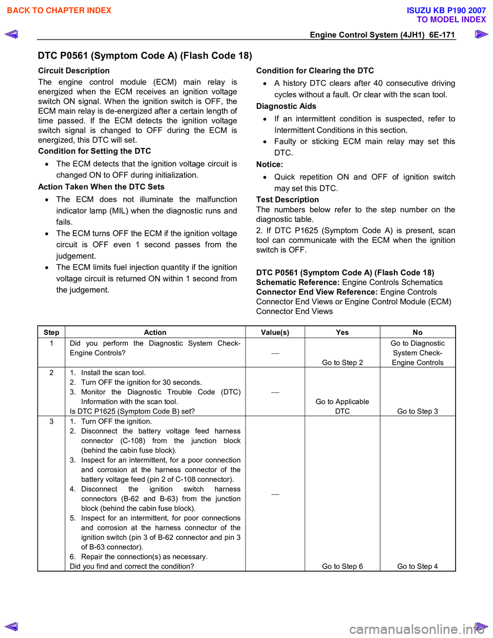
DTC P0561 (Symptom Code A) (Flash Code 18)
Circuit Description
The engine control module (ECM) main relay is
energized when the ECM receives an ignition voltage
switch ON signal. W hen the ignition switch is OFF, the
ECM main relay is de-energized after a certain length o
f
time passed. If the ECM detects the ignition voltage
switch signal is changed to OFF during the ECM is
energized, this DTC will set.
Condition for Setting the DTC
• The ECM detects that the ignition voltage circuit is
changed ON to OFF during initialization.
Action Taken When the DTC Sets
• The ECM does not illuminate the malfunction
indicator lamp (MIL) when the diagnostic runs and
fails.
• The ECM turns OFF the ECM if the ignition voltage
circuit is OFF even 1 second passes from the
judgement.
• The ECM limits fuel injection quantity if the ignition
voltage circuit is returned ON within 1 second from
the judgement.
Condition for Clearing the DTC
• A history DTC clears after 40 consecutive driving
cycles without a fault. Or clear with the scan tool.
Diagnostic Aids
• If an intermittent condition is suspected, refer to
Intermittent Conditions in this section.
• Faulty or sticking ECM main relay may set this
DTC.
Notice:
• Quick repetition ON and OFF of ignition switch
may set this DTC.
Test Description
The numbers below refer to the step number on the
diagnostic table.
2. If DTC P1625 (Symptom Code A) is present, scan
tool can communicate with the ECM when the ignition
switch is OFF.
DTC P0561 (Symptom Code A) (Flash Code 18)
Schematic Reference: Engine Controls Schematics
Connector End View Reference: Engine Controls
Connector End Views or Engine Control Module (ECM)
Connector End Views
Step Action Value(s) Yes No
1 Did you perform the Diagnostic System Check-
Engine Controls?
Go to Step 2 Go to Diagnostic
System Check-
Engine Controls
2 1. Install the scan tool. 2. Turn OFF the ignition for 30 seconds.
3. Monitor the Diagnostic Trouble Code (DTC) Information with the scan tool.
Is DTC P1625 (Symptom Code B) set?
Go to Applicable DTC Go to Step 3
3 1. Turn OFF the ignition. 2. Disconnect the battery voltage feed harness connector (C-108) from the junction block
(behind the cabin fuse block).
3. Inspect for an intermittent, for a poor connection and corrosion at the harness connector of the
battery voltage feed (pin 2 of C-108 connector).
4. Disconnect the ignition switch harness connectors (B-62 and B-63) from the junction
block (behind the cabin fuse block).
5. Inspect for an intermittent, for poor connections and corrosion at the harness connector of the
ignition switch (pin 3 of B-62 connector and pin 3
of B-63 connector).
6. Repair the connection(s) as necessary.
Did you find and correct the condition?
Go to Step 6 Go to Step 4
BACK TO CHAPTER INDEX
TO MODEL INDEX
ISUZU KB P190 2007
Page 1207 of 6020
Engine Control System (4JH1) 6E-173
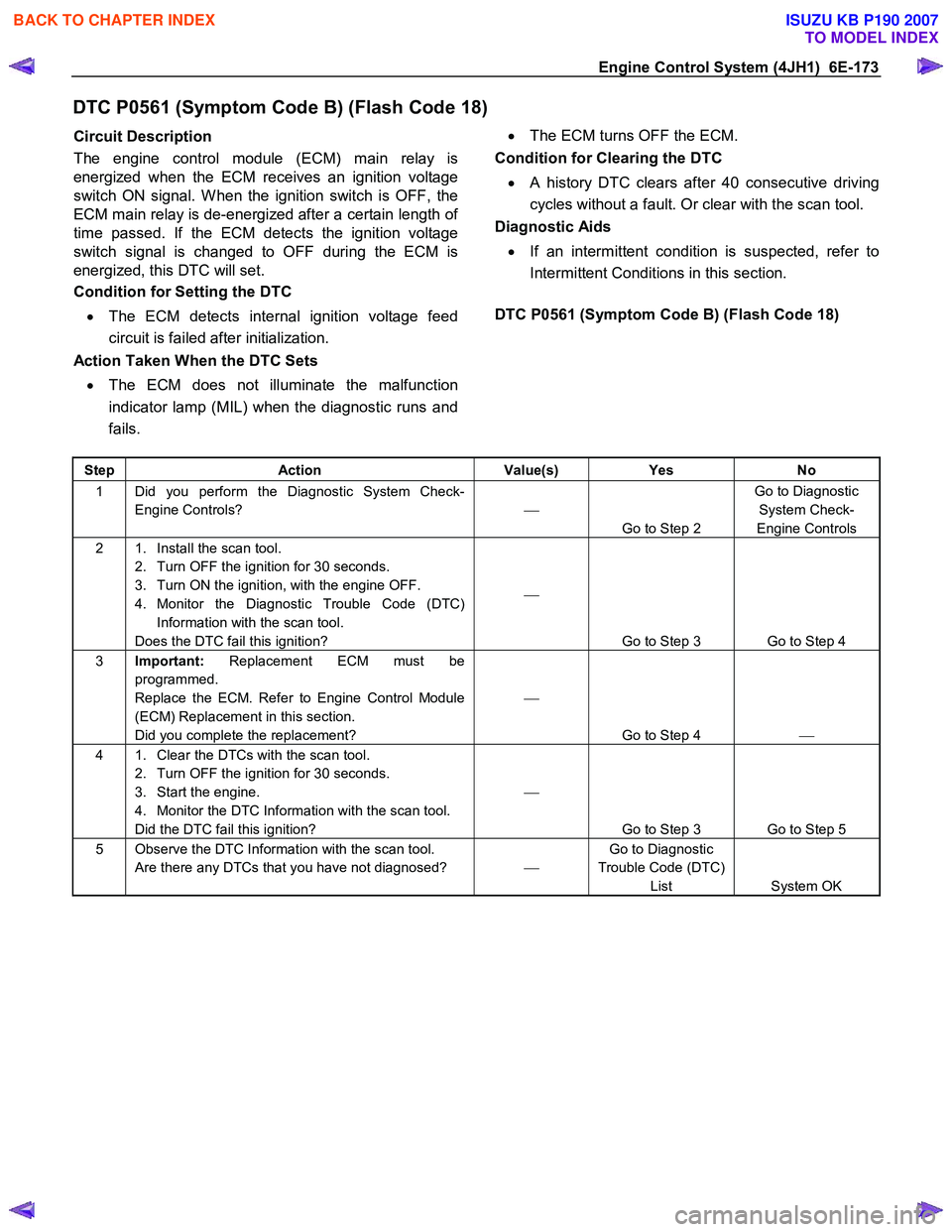
DTC P0561 (Symptom Code B) (Flash Code 18)
Circuit Description
The engine control module (ECM) main relay is
energized when the ECM receives an ignition voltage
switch ON signal. W hen the ignition switch is OFF, the
ECM main relay is de-energized after a certain length o
f
time passed. If the ECM detects the ignition voltage
switch signal is changed to OFF during the ECM is
energized, this DTC will set.
Condition for Setting the DTC
• The ECM detects internal ignition voltage feed
circuit is failed after initialization.
Action Taken When the DTC Sets
• The ECM does not illuminate the malfunction
indicator lamp (MIL) when the diagnostic runs and
fails.
•
The ECM turns OFF the ECM.
Condition for Clearing the DTC
• A history DTC clears after 40 consecutive driving
cycles without a fault. Or clear with the scan tool.
Diagnostic Aids
• If an intermittent condition is suspected, refer to
Intermittent Conditions in this section.
DTC P0561 (Symptom Code B) (Flash Code 18)
Step Action Value(s) Yes No
1 Did you perform the Diagnostic System Check-
Engine Controls?
Go to Step 2 Go to Diagnostic
System Check-
Engine Controls
2 1. Install the scan tool. 2. Turn OFF the ignition for 30 seconds.
3. Turn ON the ignition, with the engine OFF.
4. Monitor the Diagnostic Trouble Code (DTC) Information with the scan tool.
Does the DTC fail this ignition?
Go to Step 3 Go to Step 4
3 Important: Replacement ECM must be
programmed.
Replace the ECM. Refer to Engine Control Module
(ECM) Replacement in this section.
Did you complete the replacement?
Go to Step 4
4 1. Clear the DTCs with the scan tool.
2. Turn OFF the ignition for 30 seconds.
3. Start the engine.
4. Monitor the DTC Information with the scan tool.
Did the DTC fail this ignition?
Go to Step 3 Go to Step 5
5 Observe the DTC Information with the scan tool. Are there any DTCs that you have not diagnosed? Go to Diagnostic
Trouble Code (DTC) List System OK
BACK TO CHAPTER INDEX
TO MODEL INDEX
ISUZU KB P190 2007
Page 1256 of 6020
6E-222 Engine Control System (4JH1)
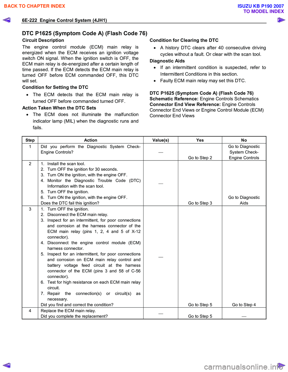
DTC P1625 (Symptom Code A) (Flash Code 76)
Circuit Description
The engine control module (ECM) main relay is
energized when the ECM receives an ignition voltage
switch ON signal. W hen the ignition switch is OFF, the
ECM main relay is de-energized after a certain length o
f
time passed. If the ECM detects the ECM main relay is
turned OFF before ECM commanded OFF, this DTC
will set.
Condition for Setting the DTC
• The ECM detects that the ECM main relay is
turned OFF before commanded turned OFF.
Action Taken When the DTC Sets • The ECM does not illuminate the malfunction
indicator lamp (MIL) when the diagnostic runs and
fails.
Condition for Clearing the DTC
• A history DTC clears after 40 consecutive driving
cycles without a fault. Or clear with the scan tool.
Diagnostic Aids
• If an intermittent condition is suspected, refer to
Intermittent Conditions in this section.
• Faulty ECM main relay may set this DTC.
DTC P1625 (Symptom Code A) (Flash Code 76)
Schematic Reference: Engine Controls Schematics
Connector End View Reference: Engine Controls
Connector End Views or Engine Control Module (ECM)
Connector End Views
Step Action Value(s) Yes No
1 Did you perform the Diagnostic System Check-
Engine Controls?
Go to Step 2 Go to Diagnostic
System Check-
Engine Controls
2 1. Install the scan tool. 2. Turn OFF the ignition for 30 seconds.
3. Turn ON the ignition, with the engine OFF.
4. Monitor the Diagnostic Trouble Code (DTC) Information with the scan tool.
5. Turn OFF the ignition.
6. Turn ON the ignition, with the engine OFF.
Does the DTC fail this ignition?
Go to Step 3 Go to Diagnostic
Aids
3 1. Turn OFF the ignition. 2. Disconnect the ECM main relay.
3. Inspect for an intermittent, for poor connections and corrosion at the harness connector of the
ECM main relay (pins 1, 2, 4 and 5 of X-12
connector).
4. Disconnect the engine control module (ECM) harness connector.
5. Inspect for an intermittent, for poor connections and corrosion on ECM main relay control and
battery voltage feed circuit at the harness
connector of the ECM (pins 3 and 58 of C-56
connector).
6. Test for high resistance on each ECM main relay circuit.
7. Repair the connection(s) or circuit(s) as necessary.
Did you find and correct the condition?
Go to Step 5 Go to Step 4
4 Replace the ECM main relay. Did you complete the replacement?
Go to Step 5
BACK TO CHAPTER INDEX
TO MODEL INDEX
ISUZU KB P190 2007
Page 1258 of 6020
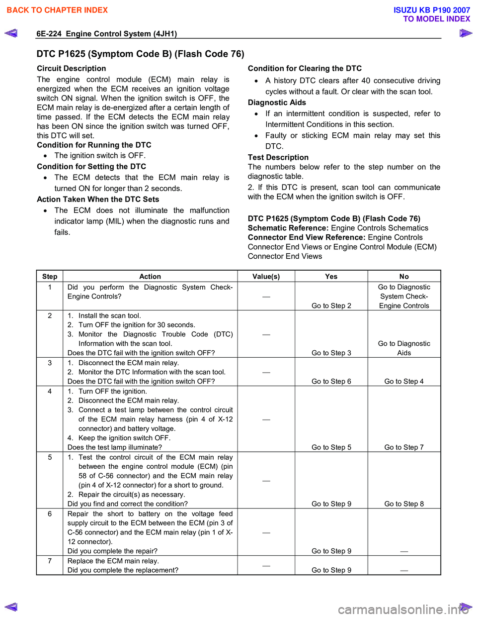
6E-224 Engine Control System (4JH1)
DTC P1625 (Symptom Code B) (Flash Code 76)
Circuit Description
The engine control module (ECM) main relay is
energized when the ECM receives an ignition voltage
switch ON signal. W hen the ignition switch is OFF, the
ECM main relay is de-energized after a certain length o
f
time passed. If the ECM detects the ECM main relay
has been ON since the ignition switch was turned OFF,
this DTC will set.
Condition for Running the DTC
• The ignition switch is OFF.
Condition for Setting the DTC • The ECM detects that the ECM main relay is
turned ON for longer than 2 seconds.
Action Taken When the DTC Sets • The ECM does not illuminate the malfunction
indicator lamp (MIL) when the diagnostic runs and
fails.
Condition for Clearing the DTC
• A history DTC clears after 40 consecutive driving
cycles without a fault. Or clear with the scan tool.
Diagnostic Aids
• If an intermittent condition is suspected, refer to
Intermittent Conditions in this section.
• Faulty or sticking ECM main relay may set this
DTC.
Test Description
The numbers below refer to the step number on the
diagnostic table.
2. If this DTC is present, scan tool can communicate
with the ECM when the ignition switch is OFF.
DTC P1625 (Symptom Code B) (Flash Code 76)
Schematic Reference: Engine Controls Schematics
Connector End View Reference: Engine Controls
Connector End Views or Engine Control Module (ECM)
Connector End Views
Step Action Value(s) Yes No
1 Did you perform the Diagnostic System Check-
Engine Controls?
Go to Step 2 Go to Diagnostic
System Check-
Engine Controls
2 1. Install the scan tool. 2. Turn OFF the ignition for 30 seconds.
3. Monitor the Diagnostic Trouble Code (DTC) Information with the scan tool.
Does the DTC fail with the ignition switch OFF?
Go to Step 3 Go to Diagnostic
Aids
3 1. Disconnect the ECM main relay. 2. Monitor the DTC Information with the scan tool.
Does the DTC fail with the ignition switch OFF?
Go to Step 6 Go to Step 4
4 1. Turn OFF the ignition. 2. Disconnect the ECM main relay.
3. Connect a test lamp between the control circuit of the ECM main relay harness (pin 4 of X-12
connector) and battery voltage.
4. Keep the ignition switch OFF.
Does the test lamp illuminate?
Go to Step 5 Go to Step 7
5 1. Test the control circuit of the ECM main relay between the engine control module (ECM) (pin
58 of C-56 connector) and the ECM main relay
(pin 4 of X-12 connector) for a short to ground.
2. Repair the circuit(s) as necessary.
Did you find and correct the condition?
Go to Step 9 Go to Step 8
6 Repair the short to battery on the voltage feed supply circuit to the ECM between the ECM (pin 3 of
C-56 connector) and the ECM main relay (pin 1 of X-
12 connector).
Did you complete the repair?
Go to Step 9
7 Replace the ECM main relay.
Did you complete the replacement?
Go to Step 9
BACK TO CHAPTER INDEX
TO MODEL INDEX
ISUZU KB P190 2007
Page 1273 of 6020
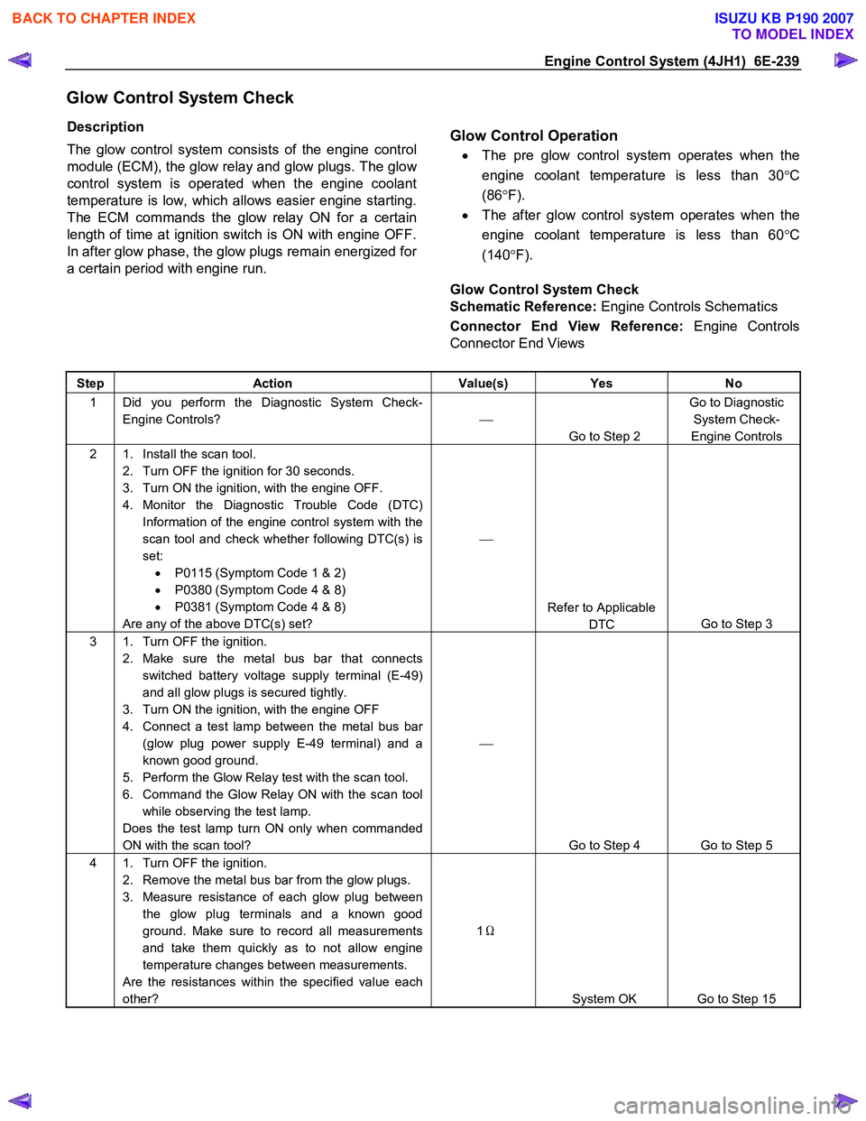
Engine Control System (4JH1) 6E-239
Glow Control System Check
Description
The glow control system consists of the engine control
module (ECM), the glow relay and glow plugs. The glo
w
control system is operated when the engine coolant
temperature is low, which allows easier engine starting.
The ECM commands the glow relay ON for a certain
length of time at ignition switch is ON with engine OFF.
In after glow phase, the glow plugs remain energized fo
r
a certain period with engine run.
Glow Control Operation
•
The pre glow control system operates when the
engine coolant temperature is less than 30 °C
(86 °F).
• The after glow control system operates when the
engine coolant temperature is less than 60 °C
(140 °F).
Glow Control System Check
Schematic Reference: Engine Controls Schematics
Connector End View Reference: Engine Controls
Connector End Views
Step Action Value(s) Yes No
1 Did you perform the Diagnostic System Check-
Engine Controls?
Go to Step 2 Go to Diagnostic
System Check-
Engine Controls
2 1. Install the scan tool. 2. Turn OFF the ignition for 30 seconds.
3. Turn ON the ignition, with the engine OFF.
4. Monitor the Diagnostic Trouble Code (DTC) Information of the engine control system with the
scan tool and check whether following DTC(s) is
set: • P0115 (Symptom Code 1 & 2)
• P0380 (Symptom Code 4 & 8)
• P0381 (Symptom Code 4 & 8)
Are any of the above DTC(s) set?
Refer to Applicable DTC Go to Step 3
3 1. Turn OFF the ignition.
2. Make sure the metal bus bar that connects switched battery voltage supply terminal (E-49)
and all glow plugs is secured tightly.
3. Turn ON the ignition, with the engine OFF
4. Connect a test lamp between the metal bus bar (glow plug power supply E-49 terminal) and a
known good ground.
5. Perform the Glow Relay test with the scan tool.
6. Command the Glow Relay ON with the scan tool while observing the test lamp.
Does the test lamp turn ON only when commanded
ON with the scan tool?
Go to Step 4 Go to Step 5
4 1. Turn OFF the ignition. 2. Remove the metal bus bar from the glow plugs.
3. Measure resistance of each glow plug between the glow plug terminals and a known good
ground. Make sure to record all measurements
and take them quickly as to not allow engine
temperature changes between measurements.
Are the resistances within the specified value each
other? 1
Ω
System OK Go to Step 15
BACK TO CHAPTER INDEX
TO MODEL INDEX
ISUZU KB P190 2007
Page 1335 of 6020
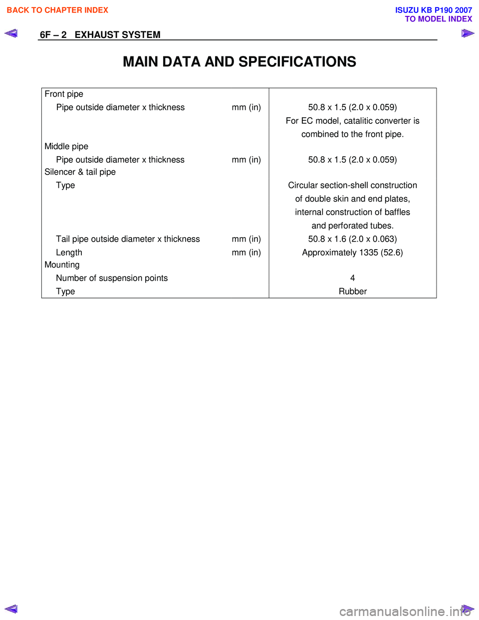
6F – 2 EXHAUST SYSTEM
MAIN DATA AND SPECIFICATIONS
Front pipe
Pipe outside diameter x thickness mm (in) 50.8 x 1.5 (2.0 x 0.059)
For EC model, catalitic converter is
combined to the front pipe.
Middle pipe
Pipe outside diameter x thickness mm (in) 50.8 x 1.5 (2.0 x 0.059)
Silencer & tail pipe
Type Circular section-shell construction
of double skin and end plates,
internal construction of baffles
and perforated tubes.
Tail pipe outside diameter x thickness mm (in) 50.8 x 1.6 (2.0 x 0.063)
Length mm (in) Approximately 1335 (52.6)
Mounting
Number of suspension points 4
Type Rubber
BACK TO CHAPTER INDEX
TO MODEL INDEX
ISUZU KB P190 2007
Page 1404 of 6020
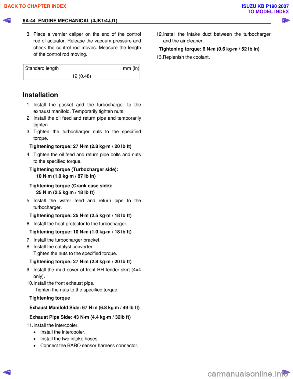
6A-44 ENGINE MECHANICAL (4JK1/4JJ1)
3. Place a vernier caliper on the end of the control
rod of actuator. Release the vacuum pressure and
check the control rod moves. Measure the length
of the control rod moving.
Standard length mm (in)
12 (0.48)
Installation
1. Install the gasket and the turbocharger to the
exhaust manifold. Temporarily tighten nuts.
2. Install the oil feed and return pipe and temporaril
y
tighten.
3. Tighten the turbocharger nuts to the specified torque.
Tightening torque: 27 N ⋅
⋅⋅
⋅
m (2.8 kg ⋅
⋅⋅
⋅
m / 20 lb ft)
4. Tighten the oil feed and return pipe bolts and nuts to the specified torque.
Tightening torque (Turbocharger side): 10 N ⋅
⋅⋅
⋅
m (1.0 kg ⋅
⋅⋅
⋅
m / 87 lb in)
Tightening torque (Crank case side): 25 N ⋅
⋅⋅
⋅
m (2.5 kg ⋅
⋅⋅
⋅
m / 18 lb ft)
5. Install the water feed and return pipe to the turbocharger.
Tightening torque: 25 N ⋅
⋅⋅
⋅
m (2.5 kg ⋅
⋅⋅
⋅
m / 18 lb ft)
6. Install the heat protector to the turbocharger. Tightening torque: 10 N ⋅
⋅⋅
⋅
m (1.0 kg ⋅
⋅⋅
⋅
m / 18 lb ft)
7. Install the turbocharger bracket.
8. Install the catalyst converter.
Tighten the nuts to the specified torque.
Tightening torque: 27 N ⋅
⋅⋅
⋅
m (2.8 kg ⋅
⋅⋅
⋅
m / 20 lb ft)
9. Install the mud cover of front RH fender skirt (4 ×4
only).
10. Install the front exhaust pipe.
Tighten the nuts to the specified torque.
Tightening torque
Exhaust Manifold Side: 67 N⋅
⋅⋅
⋅m (6.8 kg⋅
⋅⋅
⋅m / 49 lb ft)
Exhaust Pipe Side: 43 N
⋅
⋅⋅
⋅
m (4.4 kg ⋅
⋅⋅
⋅
m / 32lb ft)
11. Install the intercooler. • Install the intercooler.
• Install the two intake hoses.
• Connect the BARO sensor harness connector.
12. Install the intake duct between the turbocharge
r
and the air cleaner.
Tightening torque: 6 N ⋅
⋅⋅
⋅
m (0.6 kg ⋅
⋅⋅
⋅
m / 52 lb in)
13.Replenish the coolant.
BACK TO CHAPTER INDEX
TO MODEL INDEX
ISUZU KB P190 2007