2007 ISUZU KB P190 length
[x] Cancel search: lengthPage 1429 of 6020
ENGINE MECHANICAL (4JK1/4JJ1) 6A-69
Inspection
Inspect the valve spring
Note:
Check the valve spring visually and if there is clea
r
damage or wear, replace it.
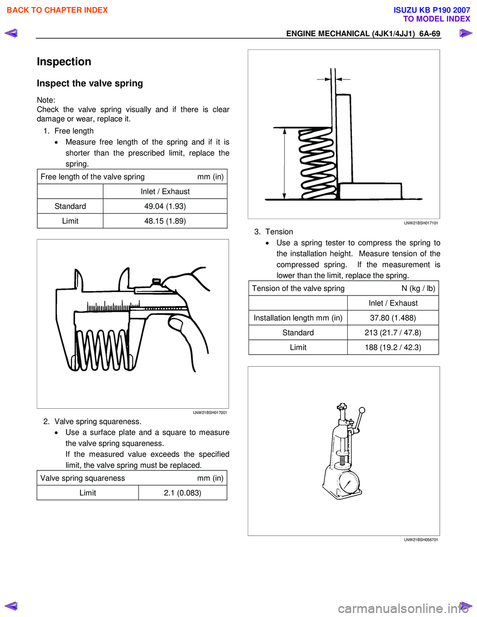
1. Free length • Measure free length of the spring and if it is
shorter than the prescribed limit, replace the
spring.
Free length of the valve spring
mm (in)
Inlet / Exhaust
Standard 49.04 (1.93)
Limit 48.15 (1.89)
LNW 21BSH017001
2. Valve spring squareness.
• Use a surface plate and a square to measure
the valve spring squareness.
If the measured value exceeds the specified limit, the valve spring must be replaced.
Valve spring squareness mm (in)
Limit 2.1 (0.083)
LNW 21BSH017101
3. Tension
• Use a spring tester to compress the spring to
the installation height. Measure tension of the
compressed spring. If the measurement is
lower than the limit, replace the spring.
Tension of the valve spring N (kg / lb)
Inlet / Exhaust
Installation length mm (in) 37.80 (1.488)
Standard 213 (21.7 / 47.8)
Limit 188 (19.2 / 42.3)
LNW 21BSH056701
BACK TO CHAPTER INDEX
TO MODEL INDEX
ISUZU KB P190 2007
Page 1466 of 6020
6A-106 ENGINE MECHANICAL (4JK1/4JJ1)
LNW 21BSH009601
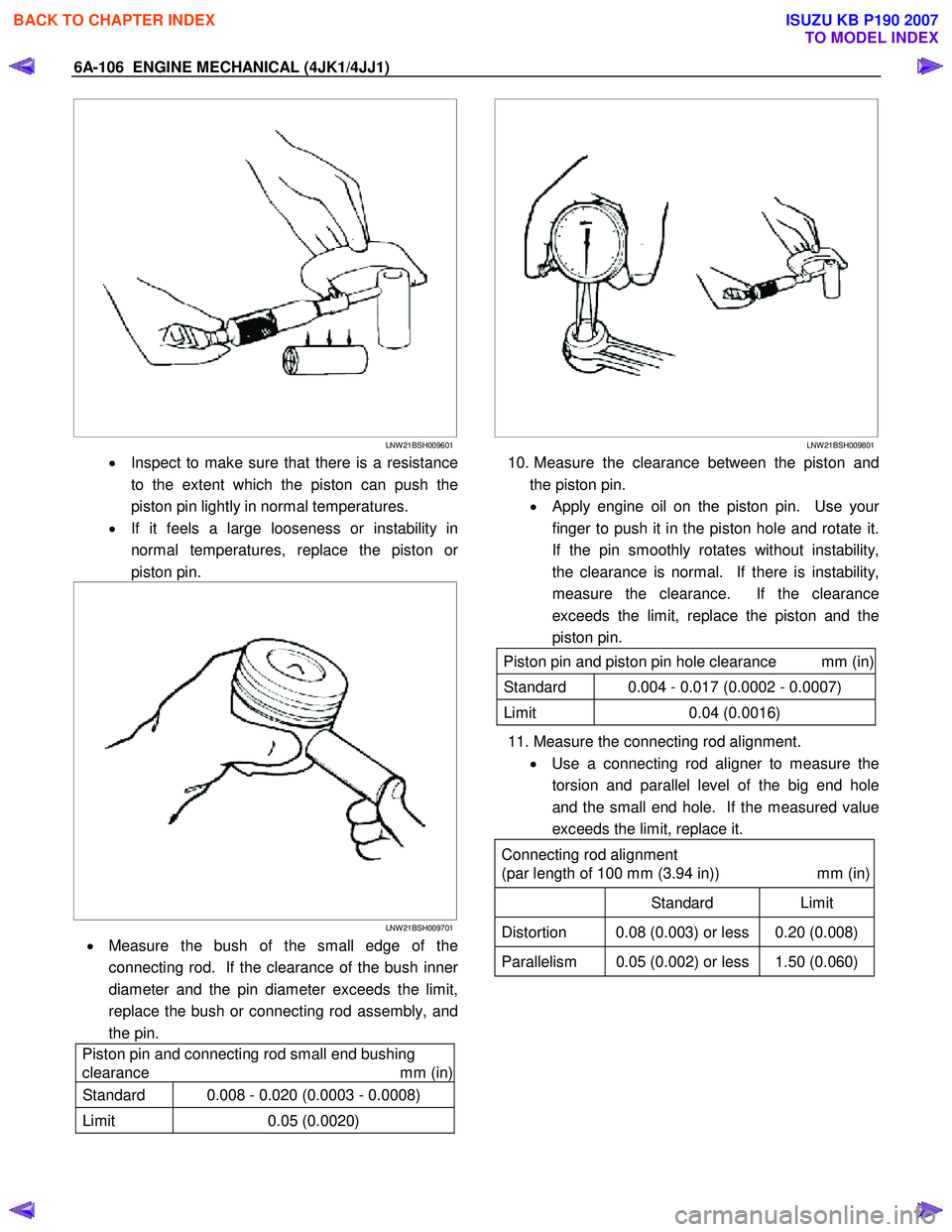
• Inspect to make sure that there is a resistance
to the extent which the piston can push the
piston pin lightly in normal temperatures.
• If it feels a large looseness or instability in
normal temperatures, replace the piston o
r
piston pin.
LNW 21BSH009701
• Measure the bush of the small edge of the
connecting rod. If the clearance of the bush inne
r
diameter and the pin diameter exceeds the limit,
replace the bush or connecting rod assembly, and
the pin.
Piston pin and connecting rod small end bushing
clearance mm (in)
Standard 0.008 - 0.020 (0.0003 - 0.0008)
Limit 0.05 (0.0020)
LNW 21BSH009801
10. Measure the clearance between the piston and
the piston pin.
•
Apply engine oil on the piston pin. Use your
finger to push it in the piston hole and rotate it.
If the pin smoothly rotates without instability,
the clearance is normal. If there is instability,
measure the clearance. If the clearance
exceeds the limit, replace the piston and the
piston pin.
Piston pin and piston pin hole clearance mm (in)
Standard 0.004 - 0.017 (0.0002 - 0.0007)
Limit 0.04 (0.0016)
11. Measure the connecting rod alignment.
• Use a connecting rod aligner to measure the
torsion and parallel level of the big end hole
and the small end hole. If the measured value
exceeds the limit, replace it.
Connecting rod alignment
(par length of 100 mm (3.94 in)) mm (in)
Standard Limit
Distortion 0.08 (0.003) or less 0.20 (0.008)
Parallelism 0.05 (0.002) or less 1.50 (0.060)
BACK TO CHAPTER INDEX
TO MODEL INDEX
ISUZU KB P190 2007
Page 1587 of 6020
6C-46 FUEL SYSTEM (4JK1/4JJ1)
Filler Neck
Removal
1. Remove the fuel tank.
Note: Refer to "Fuel Tank" in this section. 2. Put a marking on the following points as the fille
r
neck assembly is restored.
• Each joint area of the hose (to restore axial
direction and insertion length of the hose)
• Each fasten area of the clamp (to restore axial
direction and position of the clamp)
• Each bolt in the clamp (to restore fasten length
of bolt in the clamp)
• The band clip (to restore position and fasten
length of the band clip)
Note: Cover end of each hose and pipe to prevent an
y
dust entering.
Installation
1. Align each marking and restore the following point. • Each joint area of the hose (Restore axial
direction and insertion length of the hose)
• Each fasten area of the clamp (Restore axial
direction and position of the clamp)
Tightening torque: 2.5 N·m (0.25 kg ⋅
⋅⋅
⋅
m /21.7 lb in)
Filler neck side except flat deck model.
• Each bolt in the clamp (Restore fasten length o
f
bolt in the clamp)
Tightening torque: 2.5 N·m (0.25 kg ⋅
⋅⋅
⋅
m /21.7 lb in)
Filler neck side except flat deck model.
• The band clip (Restore position and fasten
length of the band clip)
2. Install the fuel tank.
Note: Refer to "Fuel Tank" in this section.
BACK TO CHAPTER INDEX
TO MODEL INDEX
ISUZU KB P190 2007
Page 1610 of 6020
6D-22 ENGINE ELECTRICAL (4JK1/4JJ1)
RTW 46DSH003901
Brush and Brush Holder
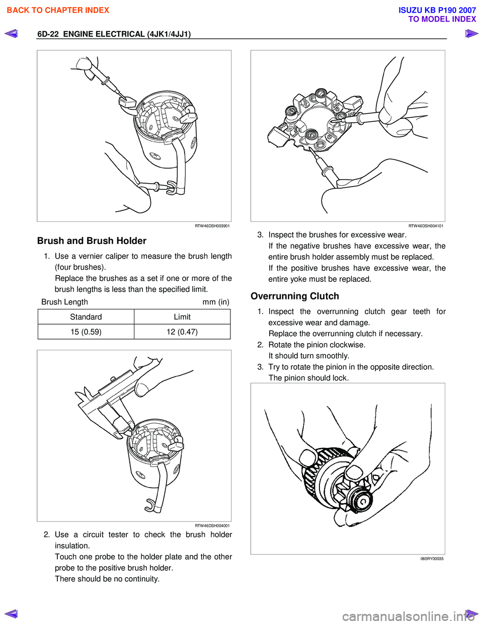
1. Use a vernier caliper to measure the brush length
(four brushes).
Replace the brushes as a set if one or more of the brush lengths is less than the specified limit.
Brush Length mm (in)
Standard Limit
15 (0.59) 12 (0.47)
RTW 46DSH004001
2. Use a circuit tester to check the brush holder
insulation.
Touch one probe to the holder plate and the othe
r
probe to the positive brush holder.
There should be no continuity.
RTW 46DSH004101
3. Inspect the brushes for excessive wear.
If the negative brushes have excessive wear, the entire brush holder assembly must be replaced.
If the positive brushes have excessive wear, the entire yoke must be replaced.
Overrunning Clutch
1. Inspect the overrunning clutch gear teeth for
excessive wear and damage.
Replace the overrunning clutch if necessary.
2. Rotate the pinion clockwise.
It should turn smoothly.
3. Try to rotate the pinion in the opposite direction.
The pinion should lock.
065RY00035
BACK TO CHAPTER INDEX
TO MODEL INDEX
ISUZU KB P190 2007
Page 1671 of 6020
6E-54 ENGINE CONTROL SYSTEM (4JK1/4JJ1)
Cruise Cancel Switch
This parameter displays the input state of the cruise
cancel switch to the ECM. When the Cruise Cancel
switch is applied, the scan tool displays Off.
Cruise Resume Switch
This parameter displays the input state of the cruise
resume/accel. switch to the ECM. When the Cruise
Resume/Accel. switch is applied, the scan tool displays
On.
Cruise Set Switch
This parameter displays the input state of the cruise
set/coast switch to the ECM. When the Cruise Set/
Coast switch is pushed, the scan tool displays On.
MIL Command (Malfunction Indicator Lamp)
This parameter displays the commanded state of the
malfunction indicator lamp (MIL) control circuit. The
MIL should be On when the scan tool indicates
command On. The MIL should be Off when the scan
tool indicates command Off.
SVS Lamp Command (Service Vehicle Soon)
This parameter displays the commanded state of the
service vehicle soon (SVS) lamp control circuit. The
SVS lamp should be On when the scan tool indicates
command On. The SVS lamp should be Off when the
scan tool indicates command Off.
Limp Home Mode
This parameter indicates the state of the limp-home
mode. None indicates limp-home mode is not applied.
1, 2, 3 and 4 indicates fuel injection quantity reduction
is applied. 2 or higher number inhibits pilot injection. If 4
is indicated, engine running will be stopped when the
vehicle speed is less than 5 km/h (3 MPH) for 5
seconds.
Distance While MIL is Activated
This parameter displays the mileage since the
malfunction indicator lamp (MIL) is turned ON.
Engine Runtime With MIL Active
This parameter displays the engine run time elapsed
since the malfunction indicator lamp (MIL) is turned
ON. The scan tool will display the time in minutes.
Total Engine Overspeed Event
This parameter indicates counter of engine overspeed
event. Counter will be zero if any DTC is cleared.
Total Engine Coolant Overtemperature Event
This parameter indicates counter of engine overheat
event. The counter is active if engine coolant is over
11 0 °C (230 °F). Counter will be zero if any DTC is
cleared. Total Fuel Temperature Overtemperature Event
This parameter indicates counter of fuel temperature
excessively high condition. The counter is active if fuel
temperature is over 95 °C (203 °F). Counter will be zero
if any DTC is cleared.
Total Intake Air Temperature Overtemperature
Event
This parameter indicates counter of intake air
temperature excessively high condition. The counter is
active if intake air temperature is over 55 °C (131 °F).
Counter will be zero if any DTC is cleared.
Immobilizer Function Programmed
This parameter displays the state of the immobilizer
function programming in the ECM. The scan tool will
display Yes or No. Yes indicates the immobilizer
security information is correctly programmed in the
ECM. No indicates the ECM is not programmed or
ECM is reset.
Wrong Immobilizer Signal
This parameter displays the input state of the received
response signal to the ECM. When the ECM received
wrong response signal from the immobilizer control unit
(ICU), the scan tool displays Yes.
Immobilizer Signal
This parameter displays the input state of the response
signal to the ECM. When the ECM received any
response signal from the immobilizer control unit (ICU),
the scan tool displays Yes.
Security Wait Time
This parameter displays the security wait time length in
the ECM. Inactive indicates not in security wait time.
Time indicates under security wait time. This wait time
stage will prevent any further attempts to enter the
security code until the wait time has elapsed. The wait
time will increase each time an incorrect security code
is entered. Note that this parameter is not count
downed. It keeps displaying the same time until that
wait time has elapsed. The ignition switch must be kept
at ON position during the wait time period.
BACK TO CHAPTER INDEX
TO MODEL INDEX
ISUZU KB P190 2007
Page 1696 of 6020
ENGINE CONTROL SYSTEM (4JK1/4JJ1) 6E-79
DTC P0088 (Flash Code 118)
Description
The common rail fuel system is comprised of two fuel
pressure sections: a suction side between the fuel tank
and the fuel supply pump and a high-pressure side
between the fuel supply pump and the fuel injectors.
Fuel is drawn from the fuel tank via a feed pump and
then pumped into the fuel rail by two plungers, all of
which are internal to the fuel supply pump. This high
pressure is regulated by the ECM using the fuel rail
pressure (FRP) regulator dependant upon values from
the FRP sensor attached to the fuel rail.
If the ECM detects that the fuel pressure went
excessively high for a certain length of time, this DTC
will set (First Stage). If the ECM detects that during the
same ignition cycle the fuel pressure rose even higher
than the amount to set DTC P0088 for a certain length
of time, the engine is stopped (Second Stage). If the
engine is stopped, the fuel pressure was too high and
the pressure limiter valve did not active or did not active
quick enough.
Condition for Running the DTC • DTCs P0192 and P0193 are not set.
• The battery voltage is more than 9 volts.
• The ignition switch is ON.
• The engine is running.
Condition for Setting the DTC
First Stage • The ECM detects that the fuel rail pressure is more than 197 MPa (28,600 psi) for longer than 5
seconds.
Second Stage
• The ECM detects that the fuel rail pressure is more than 200 MPa (29,000 psi) for longer than 5
seconds.
Action Taken When the DTC Sets
First Stage • The ECM illuminates the MIL when the diagnostic runs and fails. Refer to DTC Type Definitions for
Action Taken When the DTC Sets - Type A.
• The ECM limits fuel injection quantity.
• The ECM inhibits pilot injection.
• The ECM inhibits cruise control.
Second Stage • The ECM illuminates the SVS lamp when the
diagnostic runs and fails. Refer to DTC Type
Definitions for Action Taken When the DTC Sets -
Type C. (Euro 4 Specification)
• The ECM illuminates the MIL when the diagnostic runs and fails. Refer to DTC Type Definitions for
Action Taken When the DTC Sets - Type A.
(Except Euro 4 Specification)
• The ECM limits fuel injection quantity.
• The ECM inhibits pilot injection.
• The ECM inhibits cruise control.
• The ECM stops engine running when the vehicle speed is lower than 5 km/h (3 MPH) for 5 seconds.
The engine will run after the key is cycled when the
ignition has been tuned OFF for longer than 10
seconds.
Condition for Clearing the DTC
First Stage • Refer to DTC Type Definitions for Condition for Clearing the MIL/ DTC - Type A.
Second Stage
• Refer to DTC Type Definitions for Condition for Clearing the SVS Lamp/ DTC - Type C. (Euro 4
Specification)
• Refer to DTC Type Definitions for Condition for Clearing the MIL/ DTC - Type A. (Except Euro 4
Specification)
Diagnostic Aids • An intermittently sticking Fuel Rail Pressure regulator may have allowed the fuel pressure to
become high enough to set this DTC.
• Normal Fuel Rail Pressure readings on the scan tool with the engine running in neutral at idle is
around 27 to 33 MPa (3,900 to 48,00 psi) after
warm up.
• A skewed FRP sensor value can set this DTC. The FRP Sensor on the scan tool should read 0.9 to
1.0 volt with the key ON and engine OFF after the
engine has stopped running for a minimum of 1
minute.
Schematic Reference: Fuel System Routing Diagram
and Engine Controls Schematics
Connector End View Reference: Engine Controls
Connector End Views or ECM Connector End Views
Circuit/ System Testing DTC P0088
Step Action Value(s)Yes No
1 Did you perform the Diagnostic System Check -
Engine Controls? —
Go to Step 2 Go to Diagnostic
System Check -
Engine Controls
BACK TO CHAPTER INDEX
TO MODEL INDEX
ISUZU KB P190 2007
Page 1756 of 6020

ENGINE CONTROL SYSTEM (4JK1/4JJ1) 6E-139
DTC P0231 or P0232 (Flash Code 69)
Circuit Description
The ECM controls the fuel pump relay which supplies
power to the fuel pump in the fuel tank. The ECM
commands the fuel pump relay ON for a certain length
of time at ignition switch is ON with the engine OFF.
During the engine running it is continuously
commanded ON. If the ECM detects an improper
voltage level on the relay control circuit, DTC P0231 or
P0232 will set.
Condition for Running the DTC • The battery voltage is more than 9 volts.
• The ignition switch is ON.
Condition for Setting the DTC • The ECM detects a low voltage condition on the fuel pump relay control circuit for longer than 3
second when the relay is commanded OFF. (DTC
P0231)
• The ECM detects a high voltage condition on the fuel pump relay control circuit for longer than 3
second when the relay is commanded ON. (DTC
P0232)
Action Taken When the DTC Sets • The ECM illuminates the SVS lamp when the diagnostic runs and fails. Refer to DTC Type
Definitions for Action Taken When the DTC Sets -
Type C. (Euro 4 Specification) • The ECM illuminates the MIL when the diagnostic
runs and fails. Refer to DTC Type Definitions for
Action Taken When the DTC Sets - Type A.
(Except Euro 4 Specification)
• The ECM limits fuel injection quantity.
• The ECM inhibits cruise control.
Condition for Clearing the DTC • Refer to DTC Type Definitions for Condition for Clearing the SVS Lamp/ DTC - Type C. (Euro 4
Specification)
• Refer to DTC Type Definitions for Condition for Clearing the MIL/ DTC - Type A. (Except Euro 4
Specification)
Diagnostic Aids • If an intermittent condition is suspected, refer to Intermittent Conditions in this section.
Notice: • The fuel pump relay is commanded ON for 12 seconds at ignition switch is ON with the engine
OFF.
Schematic Reference: Engine Controls Schematics
Connector End View Reference: Engine Controls
Connector End Views or ECM Connector End Views
Circuit/ System Testing DTC P0231
Step Action Value(s)Yes No
1 Did you perform the Diagnostic System Check -
Engine Controls? —
Go to Step 2 Go to Diagnostic
System Check -
Engine Controls
2 1. Install a scan tool.
2. Turn OFF the ignition for 30 seconds.
3. Turn ON the ignition for 20 seconds while observing the DTC Information with a scan
tool.
Does the DTC fail this ignition? —
Go to Step 3 Go to Diagnostic
Aids
3 1. Turn OFF the ignition.
2. Replace the fuel pump relay with the head light relay or replace with a known good relay.
3. Turn ON the ignition for 20 seconds while observing the DTC Information with a scan
tool.
Does the DTC fail this ignition? —
Go to Step 4 Go to Step 7
BACK TO CHAPTER INDEX
TO MODEL INDEX
ISUZU KB P190 2007
Page 1854 of 6020
ENGINE CONTROL SYSTEM (4JK1/4JJ1) 6E-237
DTC P1196, P1197 or P1198 (Flash Code 461)
Circuit Description
The ECM controls the intake throttle valve opening
based on the engine running condition and by
controlling the intake throttle solenoid. The intake
throttle valve position is detected by the position
sensor, and relayed to the ECM. If the ECM detects an
excessively high temperature condition in its internal
intake throttle solenoid drive circuit for certain length of
time, DTC P1196, P1197 or P1198 will set.
Condition for Running the DTC • The battery voltage is more than 9 volts.
• The ignition switch is ON.
Condition for Setting the DTC • The ECM detects an excessively high temperature in its internal intake throttle solenoid drive circuit
for longer than 30 seconds. (DTC P1196)
• The ECM detects an excessively high temperature in its internal intake throttle solenoid drive circuit
for longer than 60 seconds in accumulation time
during same ignition cycle. (DTC P1197) • The ECM detects an excessively high temperature
in its internal intake throttle solenoid drive circuit
for longer than 120 seconds in accumulation time
exceeding ignition cycle. (DTC P1198)
Action Taken When the DTC Sets • The ECM illuminates the MIL when the diagnostic runs and fails. Refer to DTC Type Definitions for
Action Taken When the DTC Sets - Type A.
• The ECM limits fuel injection quantity.
• The ECM inhibits pilot injection.
• The ECM inhibits cruise control.
Condition for Clearing the DTC • Refer to DTC Type Definitions for Condition for Clearing the MIL/ DTC - Type A.
Diagnostic Aids • If an intermittent condition is suspected, refer to Intermittent Conditions in this section.
• A sticking or intermittently sticking intake throttle valve may set this DTC.
Circuit/ System Testing DTC P1196, P1197 or P1198
Step Action Value(s)Yes No
1 Did you perform the Diagnostic System Check -
Engine Controls? —
Go to Step 2 Go to Diagnostic
System Check -
Engine Controls
2 1. Install a scan tool.
2. Turn OFF the ignition for 30 seconds.
3. Start the engine.
4. Monitor the DTC Information with a scan tool.
Is DTC P0638 also set? —
Go to DTC P0638 Go to Step 3
3 1. Perform the Intake Throttle Solenoid Control
with a scan tool several times.
2. Command the Desired Intake Throttle Position Increase and Decrease while observing the
Intake Throttle Position.
Does the Intake Throttle Position parameter follow
within the specified value quick enough (compare
with a similar unit if available)? ±
5%
Go to Diagnostic Aids Go to Step 4
BACK TO CHAPTER INDEX
TO MODEL INDEX
ISUZU KB P190 2007