2007 ISUZU KB P190 length
[x] Cancel search: lengthPage 1865 of 6020
6E-248 ENGINE CONTROL SYSTEM (4JK1/4JJ1)
DTC P1411, P1412 or P1413 (Flash Code 445)
Circuit Description
The ECM controls the EGR valve opening based on the
engine running condition and by controlling the EGR
solenoid. The EGR valve position is detected by the
position sensor, and relayed to the ECM. If the ECM
detects an excessively high temperature condition in its
internal EGR solenoid drive circuit for certain length of
time, DTC P1411, P1412 or P1413 will set.
Condition for Running the DTC • The battery voltage is more than 9 volts.
• The ignition switch is ON.
Condition for Setting the DTC • The ECM detects an excessively high temperature in its internal EGR solenoid drive circuit for longer
than 30 seconds. (DTC P1411)
• The ECM detects an excessively high temperature in its internal EGR solenoid drive circuit for longer
than 60 seconds in accumulation time during same
ignition cycle. (DTC P1412) • The ECM detects an excessively high temperature
in its internal EGR solenoid drive circuit for longer
than 120 seconds in accumulation time exceeding
ignition cycle. (DTC P1413)
Action Taken When the DTC Sets • The ECM illuminates the MIL when the diagnostic runs and fails. Refer to DTC Type Definitions for
Action Taken When the DTC Sets - Type A.
• The ECM limits fuel injection quantity.
• The ECM inhibits pilot injection.
• The ECM inhibits cruise control.
Condition for Clearing the DTC • Refer to DTC Type Definitions for Condition for Clearing the MIL/ DTC - Type A.
Diagnostic Aids • If an intermittent condition is suspected, refer to Intermittent Conditions in this section.
• A sticking or intermittently sticking EGR valve may set this DTC.
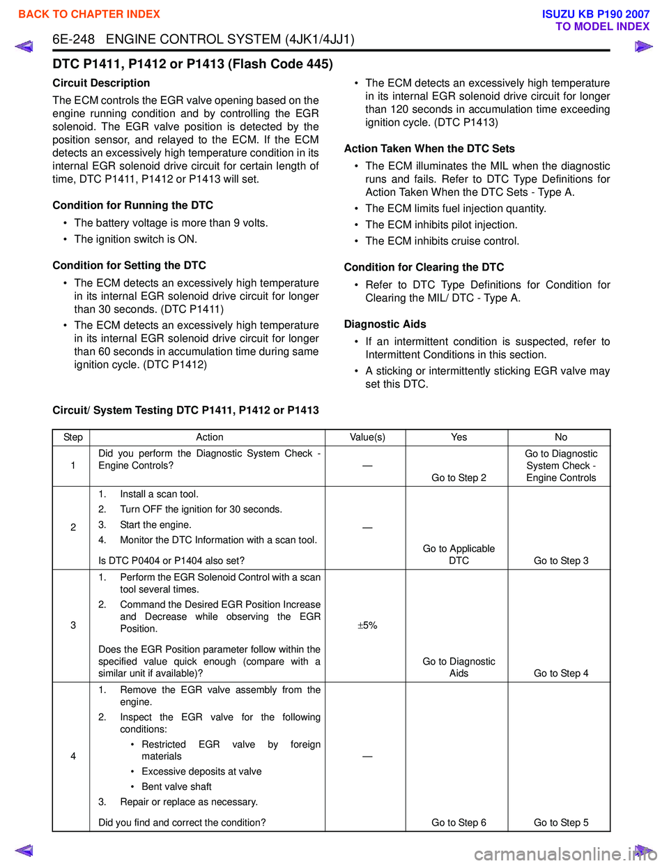
Circuit/ System Testing DTC P1411, P1412 or P1413
Step Action Value(s)Yes No
1 Did you perform the Diagnostic System Check -
Engine Controls? —
Go to Step 2 Go to Diagnostic
System Check -
Engine Controls
2 1. Install a scan tool.
2. Turn OFF the ignition for 30 seconds.
3. Start the engine.
4. Monitor the DTC Information with a scan tool.
Is DTC P0404 or P1404 also set? —
Go to Applicable DTC Go to Step 3
3 1. Perform the EGR Solenoid Control with a scan
tool several times.
2. Command the Desired EGR Position Increase and Decrease while observing the EGR
Position.
Does the EGR Position parameter follow within the
specified value quick enough (compare with a
similar unit if available)? ±
5%
Go to Diagnostic Aids Go to Step 4
4 1. Remove the EGR valve assembly from the
engine.
2. Inspect the EGR valve for the following conditions:
• Restricted EGR valve by foreign materials
• Excessive deposits at valve
• Bent valve shaft
3. Repair or replace as necessary.
Did you find and correct the condition? —
Go to Step 6 Go to Step 5
BACK TO CHAPTER INDEX
TO MODEL INDEX
ISUZU KB P190 2007
Page 1923 of 6020
6E-306 ENGINE CONTROL SYSTEM (4JK1/4JJ1)
Glow Control System Check
Description
The glow control system consists of the ECM, the glow
relay, the glow indicator lamp and glow plugs. The glow
control system is operated when the engine coolant
temperature is low, which allows easier engine starting.
The ECM commands the glow relay ON for a certain
length of time at ignition switch is ON with engine OFF.
In after glow phase, the glow plugs remain energized
for a certain period with engine run.
Glow Control Operation • The glow indicator lamp illuminates between 0.5 seconds to 7 seconds depending upon the engine
coolant temperature. • The pre glow control system operates when the
engine coolant temperature is less than 30 °C
(86 °F).
• The after glow control system operates when the engine coolant temperature is less than 60 °C
(140 °F).
Schematic Reference: Engine Controls Schematics
Connector End View Reference: Engine Controls
Connector End Views or ECM Connector End Views
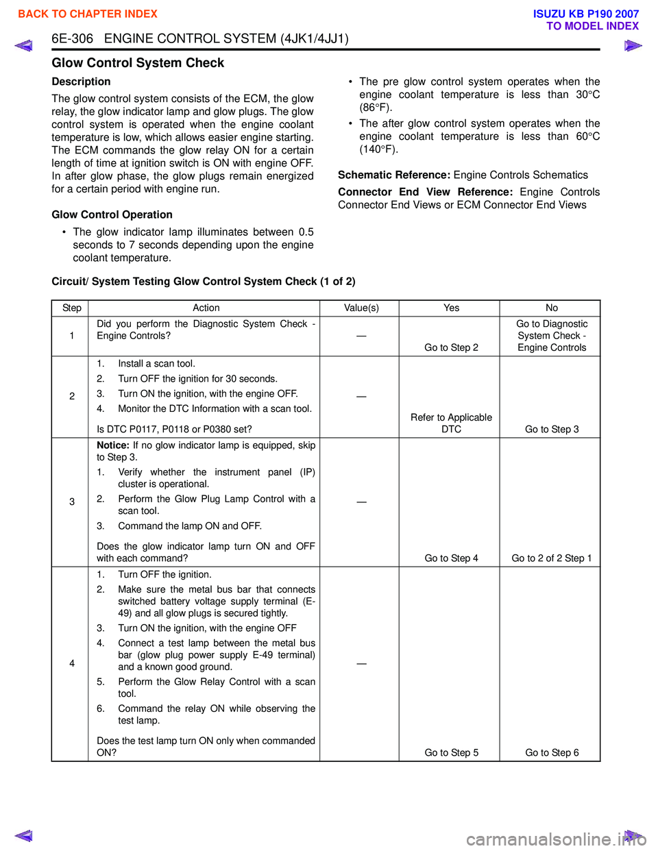
Circuit/ System Testing Glow Control System Check (1 of 2)
Step Action Value(s)Yes No
1 Did you perform the Diagnostic System Check -
Engine Controls? —
Go to Step 2 Go to Diagnostic
System Check -
Engine Controls
2 1. Install a scan tool.
2. Turn OFF the ignition for 30 seconds.
3. Turn ON the ignition, with the engine OFF.
4. Monitor the DTC Information with a scan tool.
Is DTC P0117, P0118 or P0380 set? —
Refer to Applicable DTC Go to Step 3
3 Notice:
If no glow indicator lamp is equipped, skip
to Step 3.
1. Verify whether the instrument panel (IP) cluster is operational.
2. Perform the Glow Plug Lamp Control with a scan tool.
3. Command the lamp ON and OFF.
Does the glow indicator lamp turn ON and OFF
with each command? —
Go to Step 4 Go to 2 of 2 Step 1
4 1. Turn OFF the ignition.
2. Make sure the metal bus bar that connects switched battery voltage supply terminal (E-
49) and all glow plugs is secured tightly.
3. Turn ON the ignition, with the engine OFF
4. Connect a test lamp between the metal bus bar (glow plug power supply E-49 terminal)
and a known good ground.
5. Perform the Glow Relay Control with a scan tool.
6. Command the relay ON while observing the test lamp.
Does the test lamp turn ON only when commanded
ON? —
Go to Step 5 Go to Step 6
BACK TO CHAPTER INDEX
TO MODEL INDEX
ISUZU KB P190 2007
Page 1928 of 6020
ENGINE CONTROL SYSTEM (4JK1/4JJ1) 6E-311
In-Tank Fuel Pump System Check
Description
The ECM controls the fuel pump relay, which supplies
power to the fuel pump in the fuel tank. The ECM
commands the fuel pump relay ON for a certain length
of time at ignition switch is ON with the engine OFF.
During the engine is running it is continuity commanded
ON.
In-tank Fuel Pump Control Operation • The battery voltage is more than 9 volts. • The ignition switch is ON.
• The fuel pump is commanded ON for 12 seconds at ignition switch is ON with the engine OFF.
• The fuel pump is continuously ON while engine is running.
Schematic Reference: Engine Controls Schematics
Connector End View Reference: Engine Controls
Connector End Views or ECM Connector End Views
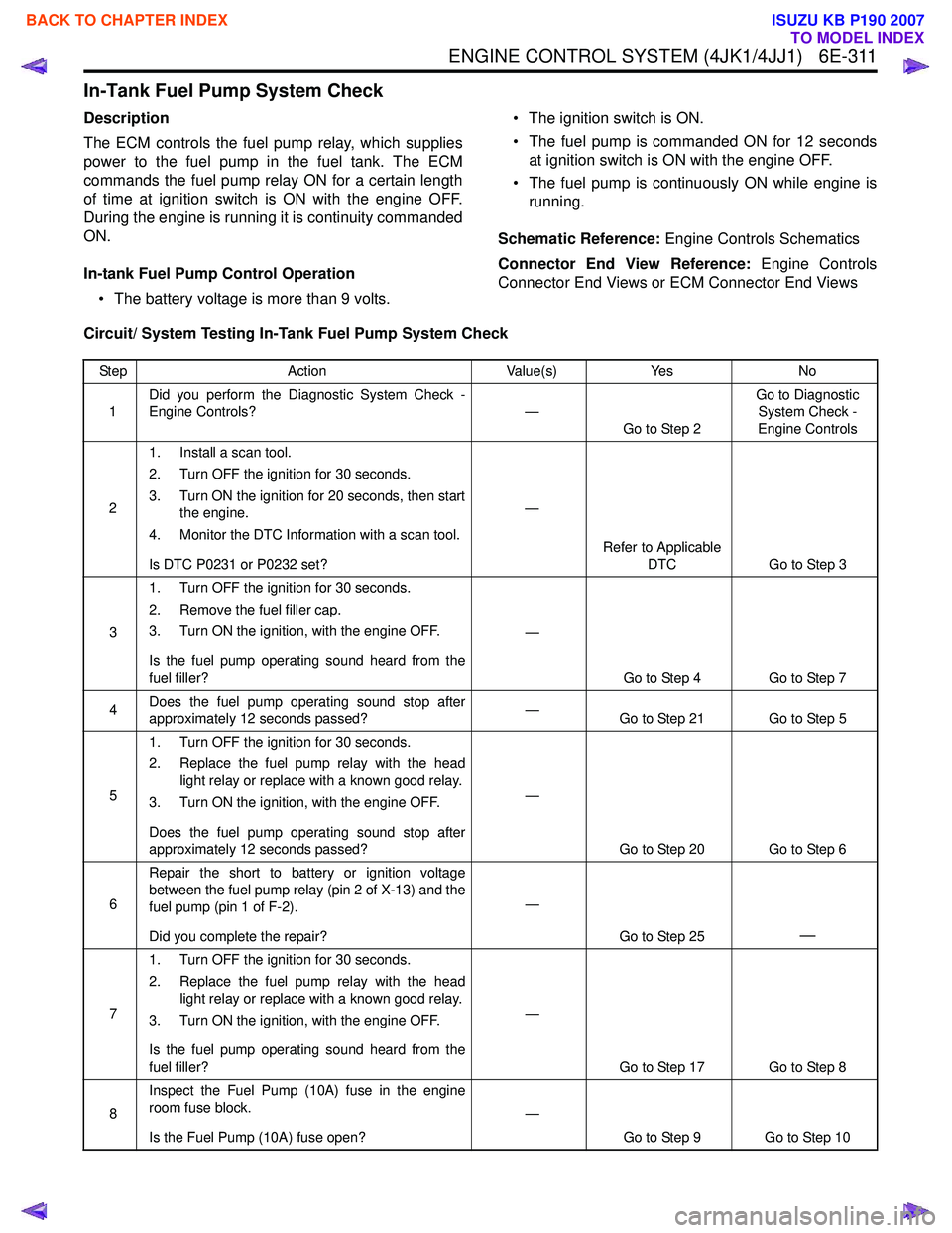
Circuit/ System Testing In-Tank Fuel Pump System Check
Step Action Value(s)Yes No
1 Did you perform the Diagnostic System Check -
Engine Controls? —
Go to Step 2 Go to Diagnostic
System Check -
Engine Controls
2 1. Install a scan tool.
2. Turn OFF the ignition for 30 seconds.
3. Turn ON the ignition for 20 seconds, then start the engine.
4. Monitor the DTC Information with a scan tool.
Is DTC P0231 or P0232 set? —
Refer to Applicable DTC Go to Step 3
3 1. Turn OFF the ignition for 30 seconds.
2. Remove the fuel filler cap.
3. Turn ON the ignition, with the engine OFF.
Is the fuel pump operating sound heard from the
fuel filler? —
Go to Step 4 Go to Step 7
4 Does the fuel pump operating sound stop after
approximately 12 seconds passed? —
Go to Step 21 Go to Step 5
5 1. Turn OFF the ignition for 30 seconds.
2. Replace the fuel pump relay with the head light relay or replace with a known good relay.
3. Turn ON the ignition, with the engine OFF.
Does the fuel pump operating sound stop after
approximately 12 seconds passed? —
Go to Step 20 Go to Step 6
6 Repair the short to battery or ignition voltage
between the fuel pump relay (pin 2 of X-13) and the
fuel pump (pin 1 of F-2).
Did you complete the repair? —
Go to Step 25
—
71. Turn OFF the ignition for 30 seconds.
2. Replace the fuel pump relay with the head light relay or replace with a known good relay.
3. Turn ON the ignition, with the engine OFF.
Is the fuel pump operating sound heard from the
fuel filler? —
Go to Step 17 Go to Step 8
8 Inspect the Fuel Pump (10A) fuse in the engine
room fuse block.
Is the Fuel Pump (10A) fuse open? —
Go to Step 9 Go to Step 10
BACK TO CHAPTER INDEX
TO MODEL INDEX
ISUZU KB P190 2007
Page 1980 of 6020
ENGINE CONTROL SYSTEM (4JK1/4JJ1) 6E-363
Along with the employment of a common rail type
electronic control fuel injection system, the fuel rail is
provided to store high pressure fuel between supply
pump and injectors. A pressure sensor and a pressure
limiter are installed on the fuel rail. The pressure sensor
detects the fuel pressure inside the fuel rail and sends
its signal to the ECM. Based on this signal, the ECM
controls the fuel pressure inside the fuel rail via the fuel
rail pressure (FRP) regulator of the supply pump. The
pressure limiter opens the valve mechanically to relieve
the pressure when the fuel pressure inside the fuel rail
is excessive.
Fuel Rail Pressure Sensor
The FRP sensor is installed to the fuel rail and it
detects the fuel pressure in the fuel rail, converts the
pressure into a voltage signal, and sends the signal to
the ECM. The ECM monitors the FRP sensor signal
voltage. Higher fuel rail pressure provides higher signal
voltage while lower pressure provides lower signal
voltage. The ECM calculates actual fuel rail pressure
(fuel pressure) from the voltage signal and uses the
result in fuel injection control and other control tasks.
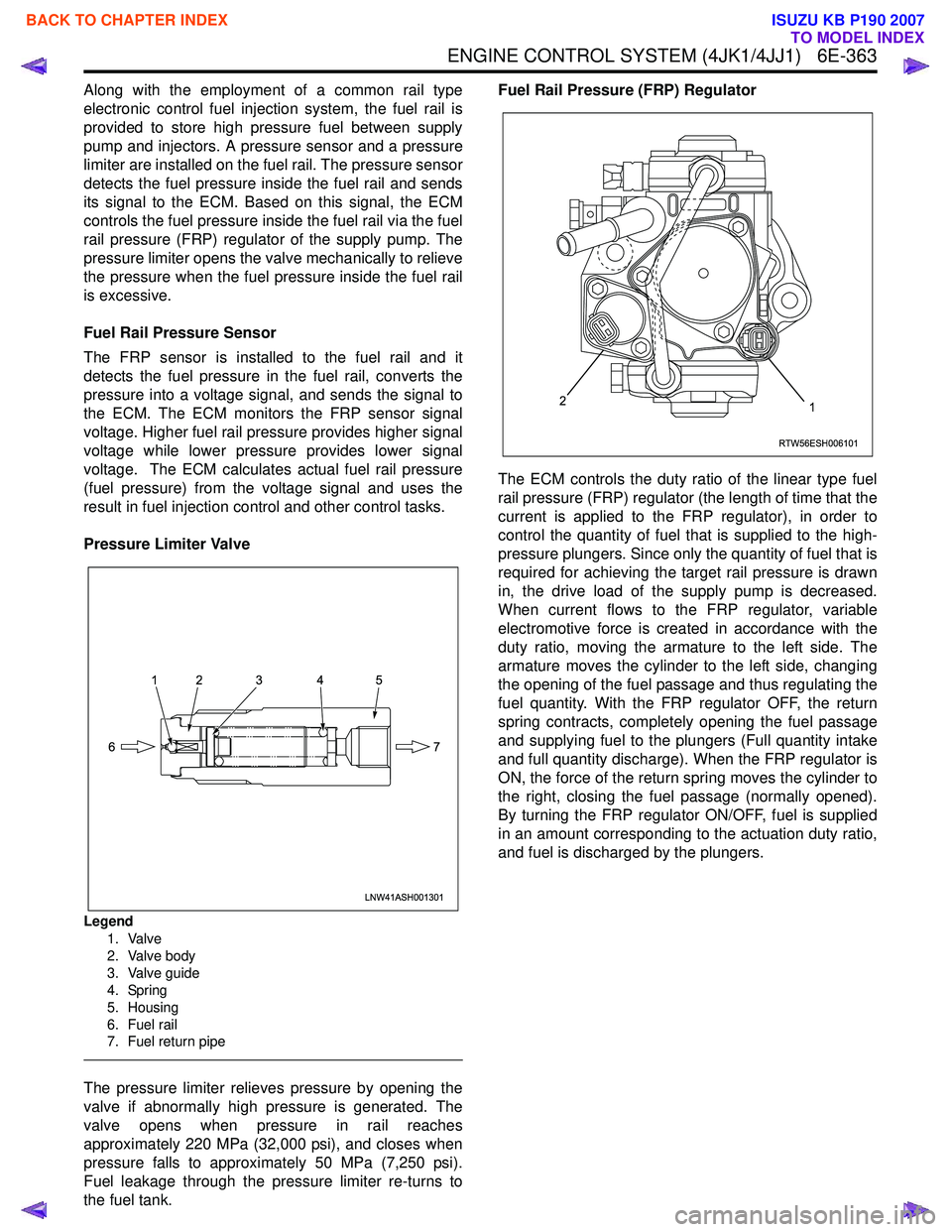
Pressure Limiter Valve
Legend 1. Valve
2. Valve body
3. Valve guide
4. Spring
5. Housing
6. Fuel rail
7. Fuel return pipe
The pressure limiter relieves pressure by opening the
valve if abnormally high pressure is generated. The
valve opens when pressure in rail reaches
approximately 220 MPa (32,000 psi), and closes when
pressure falls to approximately 50 MPa (7,250 psi).
Fuel leakage through the pressure limiter re-turns to
the fuel tank. Fuel Rail Pressure (FRP) Regulator
The ECM controls the duty ratio of the linear type fuel
rail pressure (FRP) regulator (the length of time that the
current is applied to the FRP regulator), in order to
control the quantity of fuel that is supplied to the high-
pressure plungers. Since only the quantity of fuel that is
required for achieving the target rail pressure is drawn
in, the drive load of the supply pump is decreased.
When current flows to the FRP regulator, variable
electromotive force is created in accordance with the
duty ratio, moving the armature to the left side. The
armature moves the cylinder to the left side, changing
the opening of the fuel passage and thus regulating the
fuel quantity. With the FRP regulator OFF, the return
spring contracts, completely opening the fuel passage
and supplying fuel to the plungers (Full quantity intake
and full quantity discharge). When the FRP regulator is
ON, the force of the return spring moves the cylinder to
the right, closing the fuel passage (normally opened).
By turning the FRP regulator ON/OFF, fuel is supplied
in an amount corresponding to the actuation duty ratio,
and fuel is discharged by the plungers.
LNW41ASH001301
12 3 4 5
7
6
RTW56ESH006101
12
BACK TO CHAPTER INDEX
TO MODEL INDEX
ISUZU KB P190 2007
Page 1987 of 6020
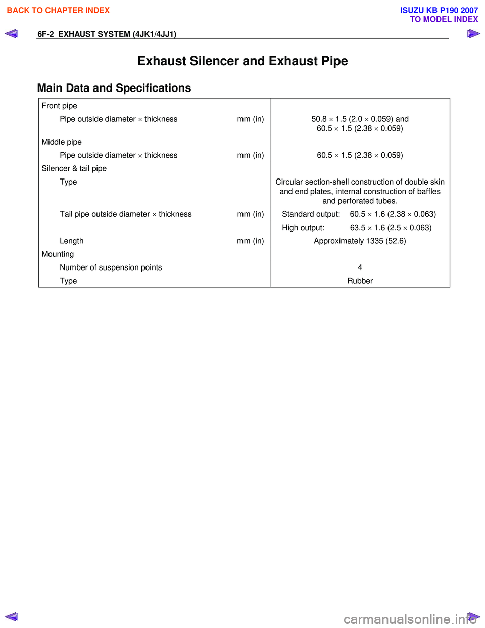
6F-2 EXHAUST SYSTEM (4JK1/4JJ1)
Exhaust Silencer and Exhaust Pipe
Main Data and Specifications
Front pipe
Pipe outside diameter × thickness mm (in)50.8 × 1.5 (2.0 × 0.059) and
60.5 × 1.5 (2.38 × 0.059)
Middle pipe
Pipe outside diameter × thickness mm (in)60.5 × 1.5 (2.38 × 0.059)
Silencer & tail pipe
Type Circular section-shell construction of double skin
and end plates, internal construction of baffles and perforated tubes.
Tail pipe outside diameter × thickness mm (in) Standard output: 60.5 × 1.6 (2.38 × 0.063)
High output: 63.5 × 1.6 (2.5 × 0.063)
Length mm (in)Approximately 1335 (52.6)
Mounting
Number of suspension points 4
Type Rubber
BACK TO CHAPTER INDEX
TO MODEL INDEX
ISUZU KB P190 2007
Page 2053 of 6020

ENGINE MECHANICAL (C24SE) 6A-39
Camshaft Housing, Check for Plane Surface
Clean
Sealing surfaces.
Inspection
Check length and width of sealing surface for deformation and
diagnosis for warpage and use straight edge feeler gauge.
Measure
Height of camshaft housing (sealing surface to sealing
surface).
Dimension I: (74.0 mm)
Cylinder Head, Removal and Installation
Important
Only remove cylinder head with engine cold (room
temperature).
Removal
1. Remove the alternator, power steering and V-belts.
Removal
2. Loosen the fastening bolts from alternator.
3. Loosen the lower alternator fastening bolt by swinging the alternator to the rear.
Removal
4. Remove the front toothed belt cover.
5. Remove the toothed belt from camshaft pulley.
See operation "Timing Check and Adjust".
BACK TO CHAPTER INDEX
TO MODEL INDEX
ISUZU KB P190 2007
Page 2070 of 6020
6A-56 ENGINE MECHANICAL (C24SE)
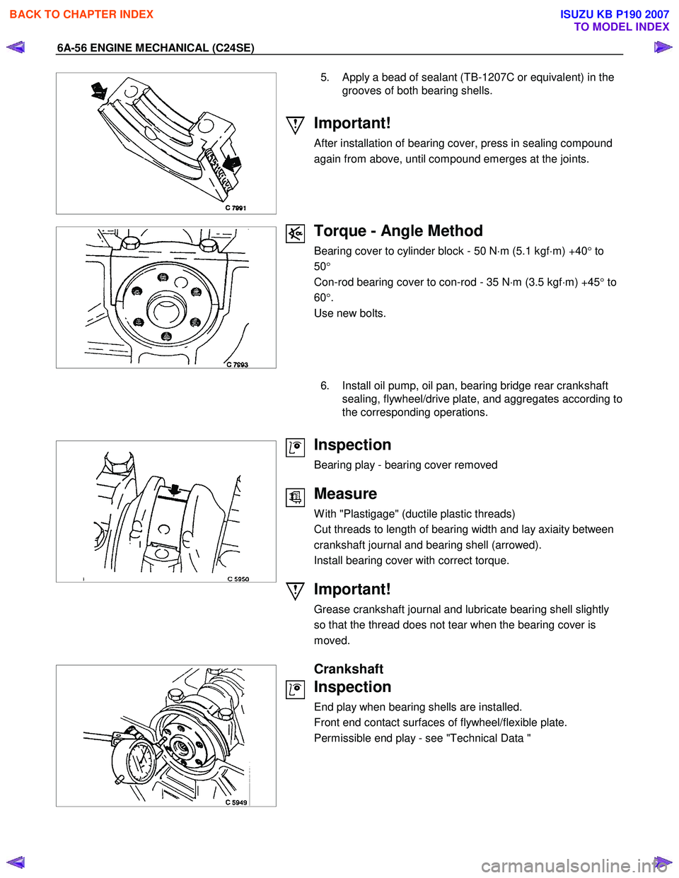
5. Apply a bead of sealant (TB-1207C or equivalent) in the grooves of both bearing shells.
Important!
After installation of bearing cover, press in sealing compound
again from above, until compound emerges at the joints.
Torque - Angle Method
Bearing cover to cylinder block - 50 N ⋅m (5.1 kgf ⋅m) +40 ° to
50 °
Con-rod bearing cover to con-rod - 35 N ⋅m (3.5 kgf ⋅m) +45 ° to
60 °.
Use new bolts.
6. Install oil pump, oil pan, bearing bridge rear crankshaft
sealing, flywheel/drive plate, and aggregates according to
the corresponding operations.
Inspection
Bearing play - bearing cover removed
Measure
W ith "Plastigage" (ductile plastic threads)
Cut threads to length of bearing width and lay axiaity between
crankshaft journal and bearing shell (arrowed).
Install bearing cover with correct torque.
Important!
Grease crankshaft journal and lubricate bearing shell slightly
so that the thread does not tear when the bearing cover is
moved.
Crankshaft
Inspection
End play when bearing shells are installed.
Front end contact surfaces of flywheel/flexible plate.
Permissible end play - see "Technical Data "
BACK TO CHAPTER INDEX
TO MODEL INDEX
ISUZU KB P190 2007
Page 2071 of 6020
ENGINE MECHANICAL (C24SE) 6A-57
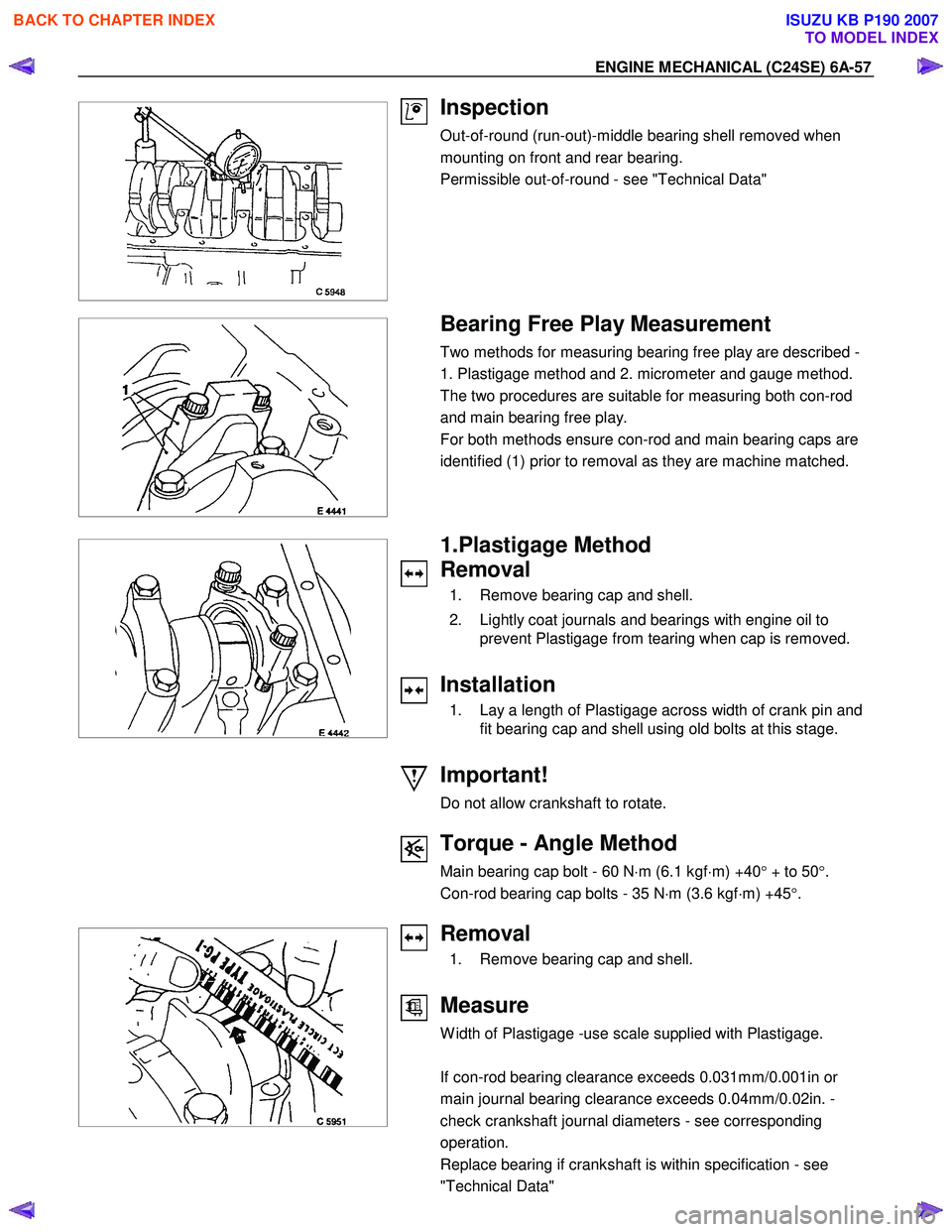
Inspection
Out-of-round (run-out)-middle bearing shell removed when
mounting on front and rear bearing.
Permissible out-of-round - see "Technical Data"
Bearing Free Play Measurement
Two methods for measuring bearing free play are described -
1. Plastigage method and 2. micrometer and gauge method.
The two procedures are suitable for measuring both con-rod
and main bearing free play.
For both methods ensure con-rod and main bearing caps are
identified (1) prior to removal as they are machine matched.
1.Plastigage Method
Removal
1. Remove bearing cap and shell.
2. Lightly coat journals and bearings with engine oil to prevent Plastigage from tearing when cap is removed.
Installation
1. Lay a length of Plastigage across width of crank pin and fit bearing cap and shell using old bolts at this stage.
Important!
Do not allow crankshaft to rotate.
Torque - Angle Method
Main bearing cap bolt - 60 N ⋅m (6.1 kgf ⋅m) +40 ° + to 50 °.
Con-rod bearing cap bolts - 35 N ⋅m (3.6 kgf ⋅m) +45 °.
Removal
1. Remove bearing cap and shell.
Measure
W idth of Plastigage -use scale supplied with Plastigage.
If con-rod bearing clearance exceeds 0.031mm/0.001in or
main journal bearing clearance exceeds 0.04mm/0.02in. -
check crankshaft journal diameters - see corresponding
operation.
Replace bearing if crankshaft is within specification - see
"Technical Data"
BACK TO CHAPTER INDEX
TO MODEL INDEX
ISUZU KB P190 2007