Page 708 of 6020

BRAKES 5C-9
MAIN DATA AND SPECIFICATIONS
FRONT DISC BRAKE mm (in) 4 × 2 HIGH RIDE
4
× 2
4 × 4
Caliper type Pin slide
Disc outside diameter 256 (10.079) 280 (11.024)
Disc thickness 26 (1.024) 27 (1.063)
Piston diameter 42.8 (1.685) × 2 45.5 (1.791) × 2
Adjustment method Self-adjusting
REAR DRUM BRAKE mm (in) 4 × 2 HIGH RIDE
4
× 2
4 × 4
Type Leading and Trailing
Drum inside diameter 254 (10.000) 295 (11.614)
Brake lining dimension 244 × 50 × 5 283 × 45 × 5
(Length × W idth × Thickness) (9.61 × 1.97 × 0.20) (11.14 × 1.77 × 0.20)
Adjustment method Self-adjusting
W HEEL CYLINDER mm (in)
Inside diameter: rear 25.4 (1.000) 23.8 (0.937)
MASTER CYLINDER mm (in)
Type Split
Bore diameter 25.4 (1.000)
Piston stroke (Primary + Secondary) 21.8 + 12 (0.86 + 0.47)
VACUUM SERVO mm (in)
Diaphragm diameter 205 (8.071) + 230 (9.055)
Power cylinder stroke 35 (1.378)
PEDAL RATIO 3.7
BALANCE
Type Load sensing proportioning valve (without ABS) /
Blend proportioning valve (without ABS)/EBD (with ABS)
BACK TO CHAPTER INDEX
TO MODEL INDEX
ISUZU KB P190 2007
Page 723 of 6020

5C-24 BRAKES
RTW 35CSH000201
3) Rear wheel cylinder fluid pressure measurement
Step on the brake pedal until the fluid pressure of the front wheel cylinder gets to 9.8Mpa (100kg/cm
2), and
check the rear wheel cylinder fluid pressure. (Read the
value of the front wheel cylinder fluid pressure 2
seconds after the measurement. W hen measuring the
LSPV fluid pressure, keep the brake pedal pressed
down without stepping it down twice or releasing it.)
Rear W heel Cylinder Fluid Pressure MPa (kg/cm
2)
2W D 6.77 ±0.83 (69.0 ±8.5)
2W D (W ith High Ride
Suspension), 4W D 6.77
±0.83 (69.0 ±8.5)
RTW 35CSH000401
2. Oil Pressure Adjustment
1) LSPV spring length adjustment
Loosen the adjust nut of the LSPV spring joint, and adjust the length of the LSPV spring.
W hen the oil pressure is insufficient, turn the adjust nut clockwise to extend the span “A”. W hen the oil pressure
is too high, turn the adjust nut counterclockwise to
reduce the span “A”.
2) After adjustment, tighten the lock nut securely.
Lock Nut Torque N⋅m (kgf ⋅m/lb ⋅ft)
11-20 (1.1-2.0/8-14)
BACK TO CHAPTER INDEX
TO MODEL INDEX
ISUZU KB P190 2007
Page 750 of 6020
BRAKES 5C-51
20. Lever; adjuster
21. Ring; Adjuster lever • Apply grease to the lever adjuster sliding surface. Install
the lever adjuster and the ring to the shoe; trailing.
• Be sure to use a new ring.
RUW 55CSH000501
22. Spring; shoe hold
23. Pin; shoe hold • Install the brake drum.
• Install the rear wheel.
• If the wheel cylinder has been removed, the brake
system must be bled.
• Pump the brake pedal 10 times. Check that there is little
or no stroke length variation as the pedal is pumped.
• Adjust the lining clearance.
•
Brake Line
Torque N ⋅m (kgf ⋅m/Ib ⋅ft)
13 - 19 (1.3 - 1.9 / 9 - 14)
BACK TO CHAPTER INDEX
TO MODEL INDEX
ISUZU KB P190 2007
Page 895 of 6020

6A – 90 ENGINE MECHANICAL
CONNECTING ROD
Connecting Rod Alignment
Use a connecting rod aligner to measure the distortion and the
parallelism between the connecting rod big end hole and the
connecting rod small end hole.
If either the measured distortion or parallelism exceed the
specified limit, the connecting rod must be replaced.
Connecting Rod Alignment Per Length of 100 mm (3.94 in)
mm (in)
Standard Limit
Distortion 0.08 (0.003) or Less 0.20 (0.008)
Parallelism 0.05 (0.002) or Less 0.15 (0.006)
Connecting Rod Side Face Clearance
1. Install the connecting rod to the crankpin.
2. Use a feeler gauge to measure the clearance between the connecting rod big end side face and the crankpin side
face.
If the measured value exceeds the specified limit, the
connecting rod must be replaced.
Connecting Rod Big End and Crankpin Side Face Clearance
mm (in)
Standard Limit
0.23 (0.009) 0.35 (0.014)
Piston Pin and Connecting Rod Small End
Bushing Clearance
Use a caliper calibrator and a dial indicator to measure the
piston pin and connecting rod small end bushing clearance.
If the clearance between the piston pin and the connecting rod
small end bushing exceeds the specified limit, replace the
piston pin and/or the connecting rod.
Piston Pin and Connecting Rod Small End
Bushing Clearance mm (in)
Standard Limit
4JA1T (L) 0.008-0.020
(0.003-0.0008) 0.050 (0.002)
4JA1TC,
4JH1TC 0.005-0.018
(0.0002-0.0007) 0.050 (0.002)
015LX034
011RY00029 015LX028
BACK TO CHAPTER INDEX
TO MODEL INDEX
ISUZU KB P190 2007
Page 980 of 6020

6C – 16 FUEL SYSTEM
FILLER NECK
Removal
1. Remove the fuel tank.
NOTE: Refer to "Fuel Tank" in this section.
2. Put a marking the following point as the filler neck assembl
y
is restored.
• Each joint area of the hose (to restore axial direction and
insertion length of the hose)
• Each fasten area of the clamp (to restore axial direction
and position of the clamp)
• Each bolt in the clamp (to restore fasten length of bolt in
the clamp)
• The band clip (to restore position and fasten length o
f
the band clip)
NOTE: Cover end of each hose and pipe to prevent any dust
entering.
Installation
1. Align each marking and restore the following point.
• Each joint area of the hose (Restore axial direction and
insertion length of the hose)
• Each fasten area of the clamp (Restore axial direction
and position of the clamp)
• Each bolt in the clamp (Restore fasten length of bolt in
the clamp)
Torque N·m (kg·m / lb ft)
2.5 (0.25 / 21.7)
filler neck side except flat deck model.
• The band clip (Restore position and fasten length of the
band clip)
2. Install the fuel tank.
NOTE: Refer to "Fuel Tank" in this section.
BACK TO CHAPTER INDEX
TO MODEL INDEX
ISUZU KB P190 2007
Page 995 of 6020
FUEL SYSTEM 6C – 31
4. Install the pin to the dial gauge.
Note:
The lengths of the pins do not include the threaded portions.
Pin (L=100 mm): 157892-5200 (Bosch AS)
Dial gauge: 157954-3800 (Bosch AS)
185317-0150 (ISUZU)
5. Secure the dial gauge to the nozzle holder using the nut so that the pin contacts the tip of the first spring
seat.
CAUTION:
• Secure the dial gauge so that a stroke of 2 mm can
be measured.
• Do not over-tighten the nut as the dial gauge shaft
may jam. (Confirm from the dial gauge that the
shaft moves smoothly.)
6. Set the nozzle holder to the nozzle tester and put needle to zero on the dial gauge.
7. Operate the nozzle tester to bleed any air from inside the retaining nut and to confirm that no fuel leaks.
040MV029.tif
040MV009.tif 040MV030.tif
BACK TO CHAPTER INDEX
TO MODEL INDEX
ISUZU KB P190 2007
Page 1014 of 6020

ENGINE ELECTRICAL 6D – 13
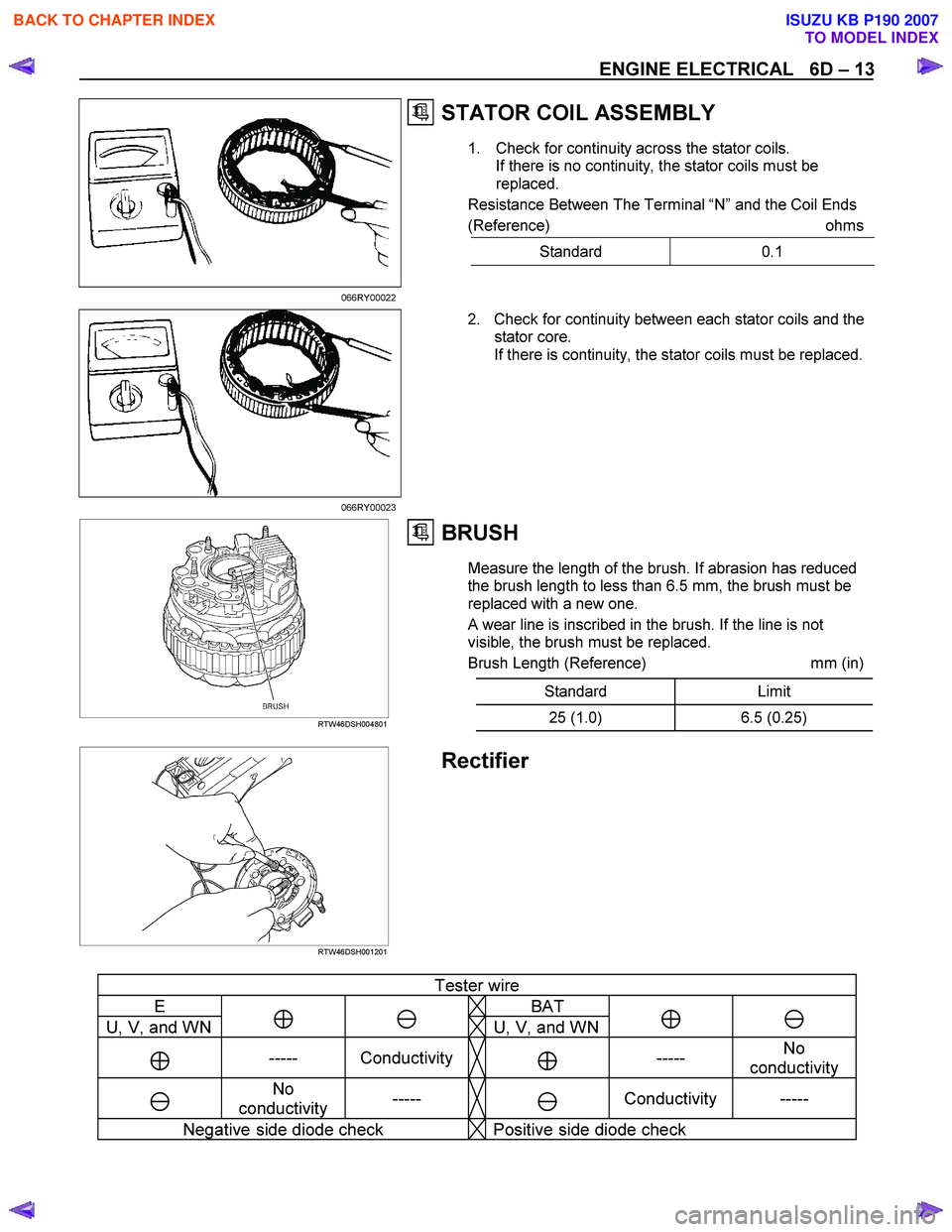
STATOR COIL ASSEMBLY
1. Check for continuity across the stator coils.
If there is no continuity, the stator coils must be
replaced.
Resistance Between The Terminal “N ” and the Coil Ends
(Reference) ohms
Standard 0.1
066RY00022 2. Check for continuity between each stator coils and the stator core.
If there is continuity, the stator coils must be replaced.
066RY00023
RTW46DSH004801
BRUSH
Measure the length of the brush. If abrasion has reduced
the brush length to less than 6.5 mm, the brush must be
replaced with a new one.
A wear line is inscribed in the brush. If the line is not
visible, the brush must be replaced.
Brush Length (Reference) mm (in)
Standard Limit
25 (1.0) 6.5 (0.25)
RTW46DSH001201
Rectifier
Tester wire
E BAT
U, V, and WN ⊕ � U, V, and WN⊕ �
⊕ ----- Conductivity ⊕ ----- No
conductivity
�
No
conductivity -----
�
Conductivity -----
Negative side diode check Positive side diode check
BACK TO CHAPTER INDEX
TO MODEL INDEX
ISUZU KB P190 2007
Page 1029 of 6020

6D – 28 ENGINE ELECTRICAL
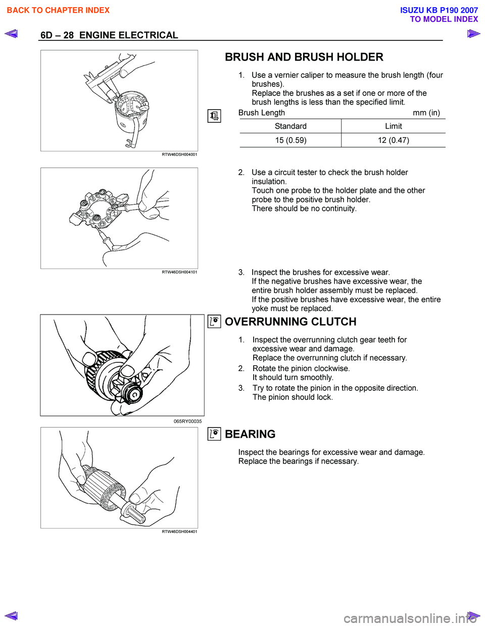
BRUSH AND BRUSH HOLDER
1. Use a vernier caliper to measure the brush length (four
brushes).
Replace the brushes as a set if one or more of the
brush lengths is less than the specified limit.
Brush Length mm (in)
Standard Limit
15 (0.59) 12 (0.47)
RTW46DSH004001
RTW46DSH004101
2. Use a circuit tester to check the brush holder
insulation.
Touch one probe to the holder plate and the other
probe to the positive brush holder.
There should be no continuity.
3. Inspect the brushes for excessive wear. If the negative brushes have excessive wear, the
entire brush holder assembly must be replaced.
If the positive brushes have excessive wear, the entire
yoke must be replaced.
OVERRUNNING CLUTCH
1. Inspect the overrunning clutch gear teeth for excessive wear and damage.
Replace the overrunning clutch if necessary.
2. Rotate the pinion clockwise. It should turn smoothly.
3. Try to rotate the pinion in the opposite direction. The pinion should lock.
065RY00035
RTW46DSH004401
BEARING
Inspect the bearings for excessive wear and damage.
Replace the bearings if necessary.
BACK TO CHAPTER INDEX
TO MODEL INDEX
ISUZU KB P190 2007