Page 3548 of 6020
Engine Management – V6 – Service Operations Page 6C1-3–24
Clean the area around the engine oil pressure
sensor before removal to avoid debris from
entering the engine.
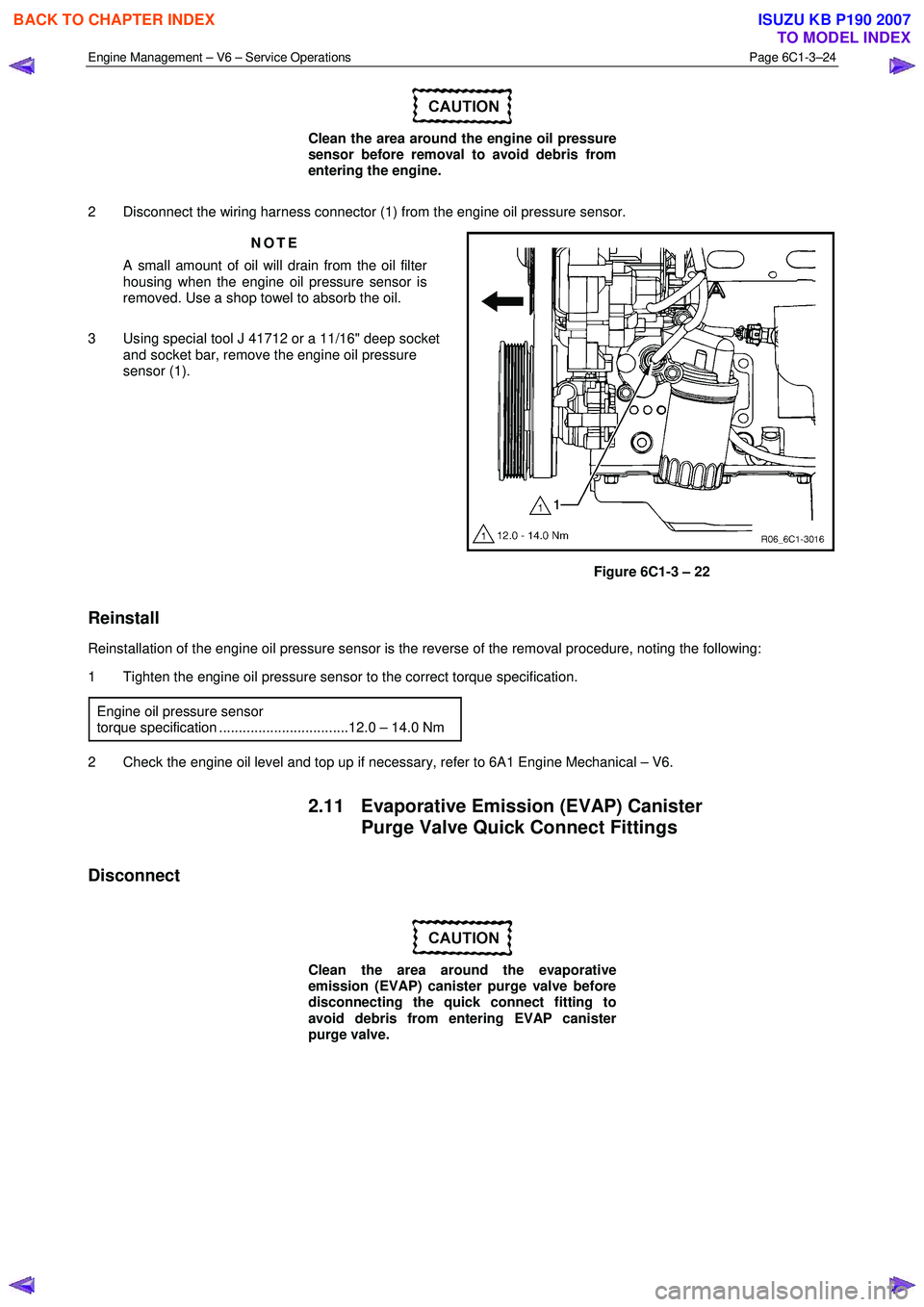
2 Disconnect the wiring harness connector (1) from the engine oil pressure sensor. NOTE
A small amount of oil will drain from the oil filter
housing when the engine oil pressure sensor is
removed. Use a shop towel to absorb the oil.
3 Using special tool J 41712 or a 11/16" deep socket and socket bar, remove the engine oil pressure
sensor (1).
Figure 6C1-3 – 22
Reinstall
Reinstallation of the engine oil pressure sensor is the reverse of the removal procedure, noting the following:
1 Tighten the engine oil pressure sensor to the correct torque specification.
Engine oil pressure sensor
torque specification .................................12.0 – 14.0 Nm
2 Check the engine oil level and top up if necessary, refer to 6A1 Engine Mechanical – V6.
2.11 Evaporative Emission (EVAP) Canister Purge Valve Quick Connect Fittings
Disconnect
Clean the area around the evaporative
emission (EVAP) canister purge valve before
disconnecting the quick connect fitting to
avoid debris from entering EVAP canister
purge valve.
BACK TO CHAPTER INDEX
TO MODEL INDEX
ISUZU KB P190 2007
Page 3550 of 6020
Engine Management – V6 – Service Operations Page 6C1-3–26
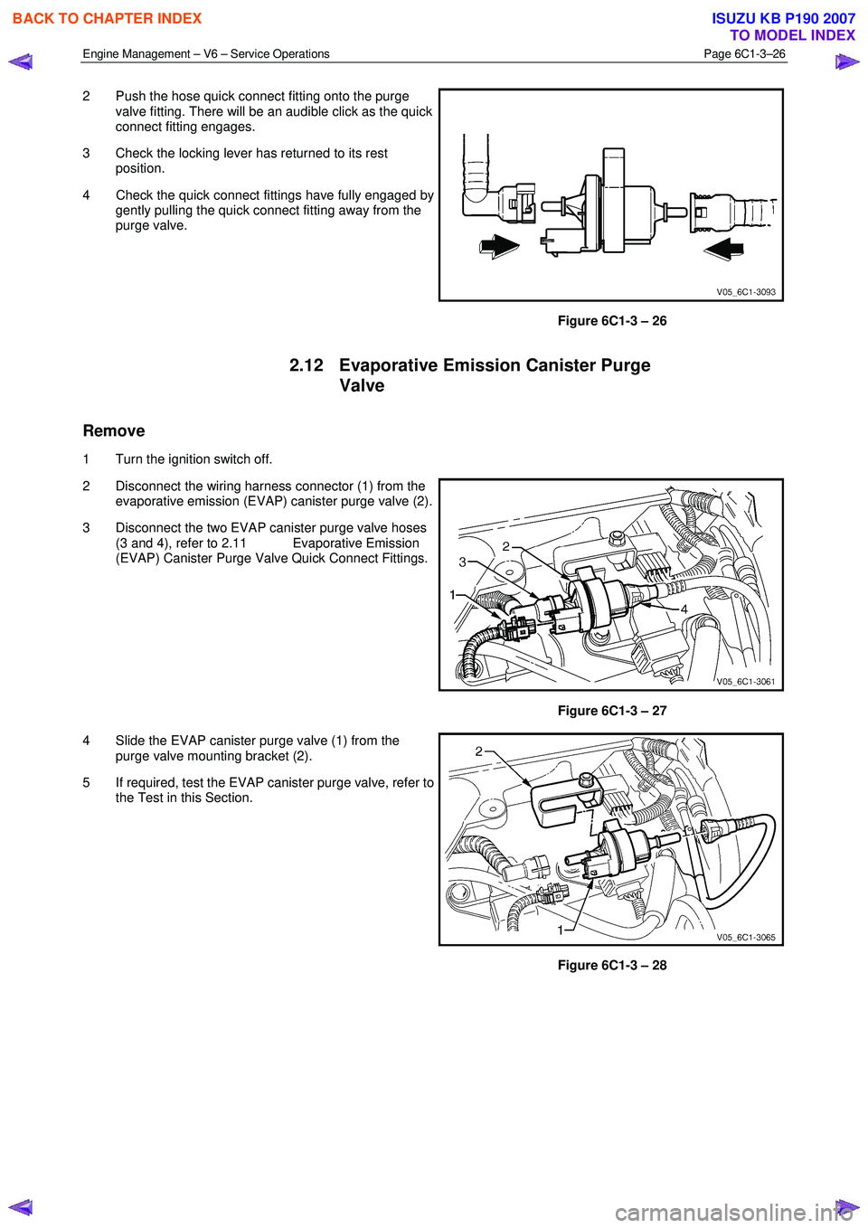
2 Push the hose quick connect fitting onto the purge
valve fitting. There will be an audible click as the quick
connect fitting engages.
3 Check the locking lever has returned to its rest position.
4 Check the quick connect fittings have fully engaged by gently pulling the quick connect fitting away from the
purge valve.
Figure 6C1-3 – 26
2.12 Evaporative Emission Canister Purge
Valve
Remove
1 Turn the ignition switch off.
2 Disconnect the wiring harness connector (1) from the evaporative emission (EVAP) canister purge valve (2).
3 Disconnect the two EVAP canister purge valve hoses (3 and 4), refer to 2.11 Evaporative Emission
(EVAP) Canister Purge Valve Quick Connect Fittings.
Figure 6C1-3 – 27
4 Slide the EVAP canister purge valve (1) from the purge valve mounting bracket (2).
5 If required, test the EVAP canister purge valve, refer to the Test in this Section.
Figure 6C1-3 – 28
BACK TO CHAPTER INDEX
TO MODEL INDEX
ISUZU KB P190 2007
Page 3567 of 6020
Engine Management – V6 – Service Operations Page 6C1-3–43
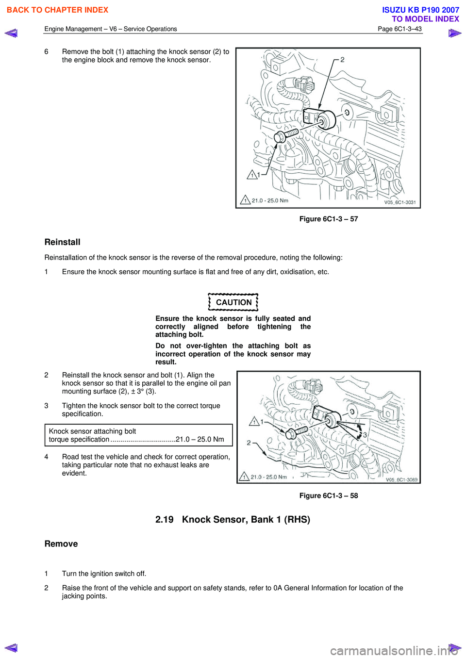
6 Remove the bolt (1) attaching the knock sensor (2) to
the engine block and remove the knock sensor.
Figure 6C1-3 – 57
Reinstall
Reinstallation of the knock sensor is the reverse of the removal procedure, noting the following:
1 Ensure the knock sensor mounting surface is flat and free of any dirt, oxidisation, etc.
Ensure the knock sensor is fully seated and
correctly aligned before tightening the
attaching bolt.
Do not over-tighten the attaching bolt as
incorrect operation of the knock sensor may
result.
2 Reinstall the knock sensor and bolt (1). Align the knock sensor so that it is parallel to the engine oil pan
mounting surface (2), ± 3° (3).
3 Tighten the knock sensor bolt to the correct torque specification.
Knock sensor attaching bolt
torque specification .................................21.0 – 25.0 Nm
4 Road test the vehicle and check for correct operation, taking particular note that no exhaust leaks are
evident.
Figure 6C1-3 – 58
2.19 Knock Sensor, Bank 1 (RHS)
Remove
1 Turn the ignition switch off.
2 Raise the front of the vehicle and support on safety stands, refer to 0A General Information for location of the jacking points.
BACK TO CHAPTER INDEX
TO MODEL INDEX
ISUZU KB P190 2007
Page 3568 of 6020
Engine Management – V6 – Service Operations Page 6C1-3–44
3 Disconnect the wiring harness connector (1) from the
knock sensor (2).
Figure 6C1-3 – 59
4 Remove the bolt (1) attaching the knock sensor (2) to the engine block, and remove the knock sensor.
Figure 6C1-3 – 60
Reinstall
Reinstallation of the knock sensor is the reverse of the removal procedure, noting the following:
1 Ensure the knock sensor mounting surface is flat and free of any dirt, oxidisation, etc.
BACK TO CHAPTER INDEX
TO MODEL INDEX
ISUZU KB P190 2007
Page 3569 of 6020

Engine Management – V6 – Service Operations Page 6C1-3–45
Ensure the knock sensor is fully seated
before tightening the attaching bolt.
Do not over-tighten the attaching bolt as
incorrect operation of the knock sensor may
result.
2 Reinstall the knock sensor and bolt (1). Align the knock sensor so that it is parallel to the engine oil pan
mounting surface (2), ± 3° (3).
3 Tighten the knock sensor bolt to the correct torque specification.
Knock sensor attaching bolt
torque specification .................................21.0 – 25.0 Nm
4 Road test the vehicle and check for correct operation.
Figure 6C1-3 – 61
2.20 Mass Air Flow Sensor
The intake air temperature (IAT) sensor is part of the mass air flow (MAF) Sensor. For the IAT sensor test procedure
refer to 2.17 Intake Air Temperature Sensor.
Handling Precautions
Under no circumstances should the MAF
sensor retaining screws (1) be loosened or
removed as the MAF will become
unserviceable and will require replacement.
Figure 6C1-3 – 62
Remove
1 Turn the ignition switch off.
BACK TO CHAPTER INDEX
TO MODEL INDEX
ISUZU KB P190 2007
Page 3571 of 6020
Engine Management – V6 – Service Operations Page 6C1-3–47
2.21 Schrader Valve – Fuel Pressure Gauge
Connection Point
If the Schrader valve is to be removed but not
replaced immediately, it is advisable to
disconnect the battery to avoid possible fuel
discharge if an accidental attempt is made to
start the engine.
Disconnection of the battery affects vehicle
electronic systems. Refer to 6D1-3 Battery –
V6 before disconnecting the battery.
Remove
1 Depressurise the fuel system, refer to 6C Fuel System - V6.
2 Turn the ignition off.
A small amount of fuel may be released when
servicing the fuel pressure test point. To
reduce the chance of personal injury, cover
the fuel pressure test point with a shop towel
to absorb any fuel spillage when the Schrader
valve sealing cap and Schrader valve are
removed. After the procedure, place the towel
in an approved container for disposal.
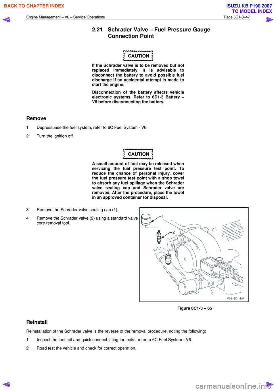
3 Remove the Schrader valve sealing cap (1).
4 Remove the Schrader valve (2) using a standard valve core removal tool.
Figure 6C1-3 – 65
Reinstall
Reinstallation of the Schrader valve is the reverse of the removal procedure, noting the following:
1 Inspect the fuel rail and quick connect fitting for leaks, refer to 6C Fuel System - V6.
2 Road test the vehicle and check for correct operation.
BACK TO CHAPTER INDEX
TO MODEL INDEX
ISUZU KB P190 2007
Page 3590 of 6020
Charging System – V6 Page 6D1-1-3
1 General Information
1.1 Components
Generator
The Mitsubishi generator can be identified visually by its two lower and one upper mounting lugs.
It is mounted to the lower right-hand side of the engine block. It is driven by the same drive belt that drives other engine
ancillaries and requires no periodic drive belt adjustment.
The generator has three phases, incorporating a rotor with six pole pairs fitted and two internal cooling fans; one on the
drive-end and one on the slip-ring end. The rotor is supported by ball bearings in both the drive and slip-ring end
housings. Surrounding the rotor is a stator, which has a three phase delta connected output winding construction on a
ring shaped lamination pack.
The output of the stator winding is rectified by eight diodes that are contained within the slip-ring end housing. Excitation
current is supplied to the rotor field coil via the voltage regulator, the brushes and slip-rings. The electronic voltage
regulator requires no adjustment in service.
The generator has four external connections (refer to Figure 6D1-1 1):
• Generator – Terminal P-9 to the battery positive terminal P-1 via fuse SBF1,
• Generator – E-4 pin 1 to the ECM connection E-60 pin 43 – regulator monitoring,
• Generator – E-4 pin 2 to the ECM connection E60 pin 21 – battery voltage sensing, and
• ground connection via the installation bolts.
Generator Types
The vehicle is fitted with a 120 amp generator.
BACK TO CHAPTER INDEX
TO MODEL INDEX
ISUZU KB P190 2007
Page 3597 of 6020
Charging System – V6 Page 6D1-1-10
3 Minor Service Operations
3.1 Safety Precautions
Observe the following precautions. Failure to observe these precautions will result in serious damage to the generator.
• Only use the generator and voltage regulator in a negative ground system.
• Always refer to 1.2 W ARNING, CAUTION and NOTES before disconnecting the battery.
• W hen installing a battery, fit the positive (+) cable to the battery before fitting the negative cable.
• W hen a slave battery is used for starting purposes, ensure that both batteries are connected in parallel. That is,
positive terminals connected and negative terminals connected.
• Only use jumper leads that have surge protection.
• Disconnect both battery cables when charging the battery. This isolates the generator from the battery and from
the external charging equipment.
• Do not operate the generator within an open circuit or without a battery in the circuit.
• Do not disconnect the battery while the generator is running.
• Do not attempt to polarise the generator.
• Do not connect generator connector E-4 pin 1 to 12 V (the battery or ignition circuits).
• Some battery powered timing lights can produce high transient voltages when connected or disconnected.
Only disconnect or connect timing lights when the engine is switched off.
Ensure the generator connector E-4 pin 1 has
a maximum sinking current of 50mA.
3.2 Maintenance
Regular Checks
Check the following at regular intervals:
• generator terminals – for corrosion and loose connections,
• wiring – for continuity and damaged insulation,
• mounting bolts – for tightness,
• drive belt – for alignment and wear, and
• drive pulley – for damage and warping.
NOTE
The drive-belt adjustment for the engine
ancillaries (i.e. generator and water pump) is
provided by a spring-loaded tensioner. Therefore,
the drive belt does not require manual
adjustment.
Lubrication
High tolerance bearings are used in this generator. If the bearings are removed during the generator disassembly, new
bearings must be installed to restore the generator to original specification. The ball bearings supporting the rotor shaft
are pre-lubricated and sealed. Do not attempt to lubricate these during servicing.
BACK TO CHAPTER INDEX
TO MODEL INDEX
ISUZU KB P190 2007