2007 ISUZU KB P190 engine mount
[x] Cancel search: engine mountPage 3276 of 6020
Engine Management – V6 – General Information Page 6C1-1–34
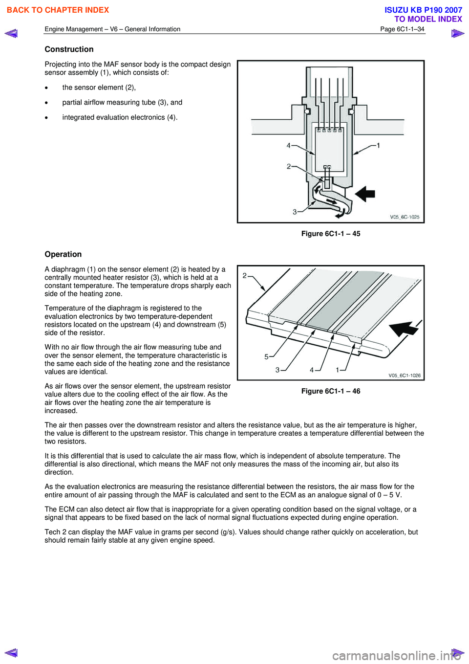
Construction
Projecting into the MAF sensor body is the compact design
sensor assembly (1), which consists of:
• the sensor element (2),
• partial airflow measuring tube (3), and
• integrated evaluation electronics (4).
Figure 6C1-1 – 45
Operation
A diaphragm (1) on the sensor element (2) is heated by a
centrally mounted heater resistor (3), which is held at a
constant temperature. The temperature drops sharply each
side of the heating zone.
Temperature of the diaphragm is registered to the
evaluation electronics by two temperature-dependent
resistors located on the upstream (4) and downstream (5)
side of the resistor.
W ith no air flow through the air flow measuring tube and
over the sensor element, the temperature characteristic is
the same each side of the heating zone and the resistance
values are identical.
As air flows over the sensor element, the upstream resistor
value alters due to the cooling effect of the air flow. As the
air flows over the heating zone the air temperature is
increased.
Figure 6C1-1 – 46
The air then passes over the downstream resistor and alters the resistance value, but as the air temperature is higher,
the value is different to the upstream resistor. This change in temperature creates a temperature differential between the
two resistors.
It is this differential that is used to calculate the air mass flow, which is independent of absolute temperature. The
differential is also directional, which means the MAF not only measures the mass of the incoming air, but also its
direction.
As the evaluation electronics are measuring the resistance differential between the resistors, the air mass flow for the
entire amount of air passing through the MAF is calculated and sent to the ECM as an analogue signal of 0 – 5 V.
The ECM can also detect air flow that is inappropriate for a given operating condition based on the signal voltage, or a
signal that appears to be fixed based on the lack of normal signal fluctuations expected during engine operation.
Tech 2 can display the MAF value in grams per second (g/s). Values should change rather quickly on acceleration, but
should remain fairly stable at any given engine speed.
BACK TO CHAPTER INDEX
TO MODEL INDEX
ISUZU KB P190 2007
Page 3278 of 6020
Engine Management – V6 – General Information Page 6C1-1–36
Intermittent
An electrical signal that occurs now and then; not continuously. In electrical circuits, refers to occasional open,
short, or ground in a circuit
Light Throttle Approximately 1/4 of accelerator pedal travel (25% throttle position)
Low
A voltage less than a specific threshold. Operates the same as a ground and may, or may not, be connected
to chassis ground.
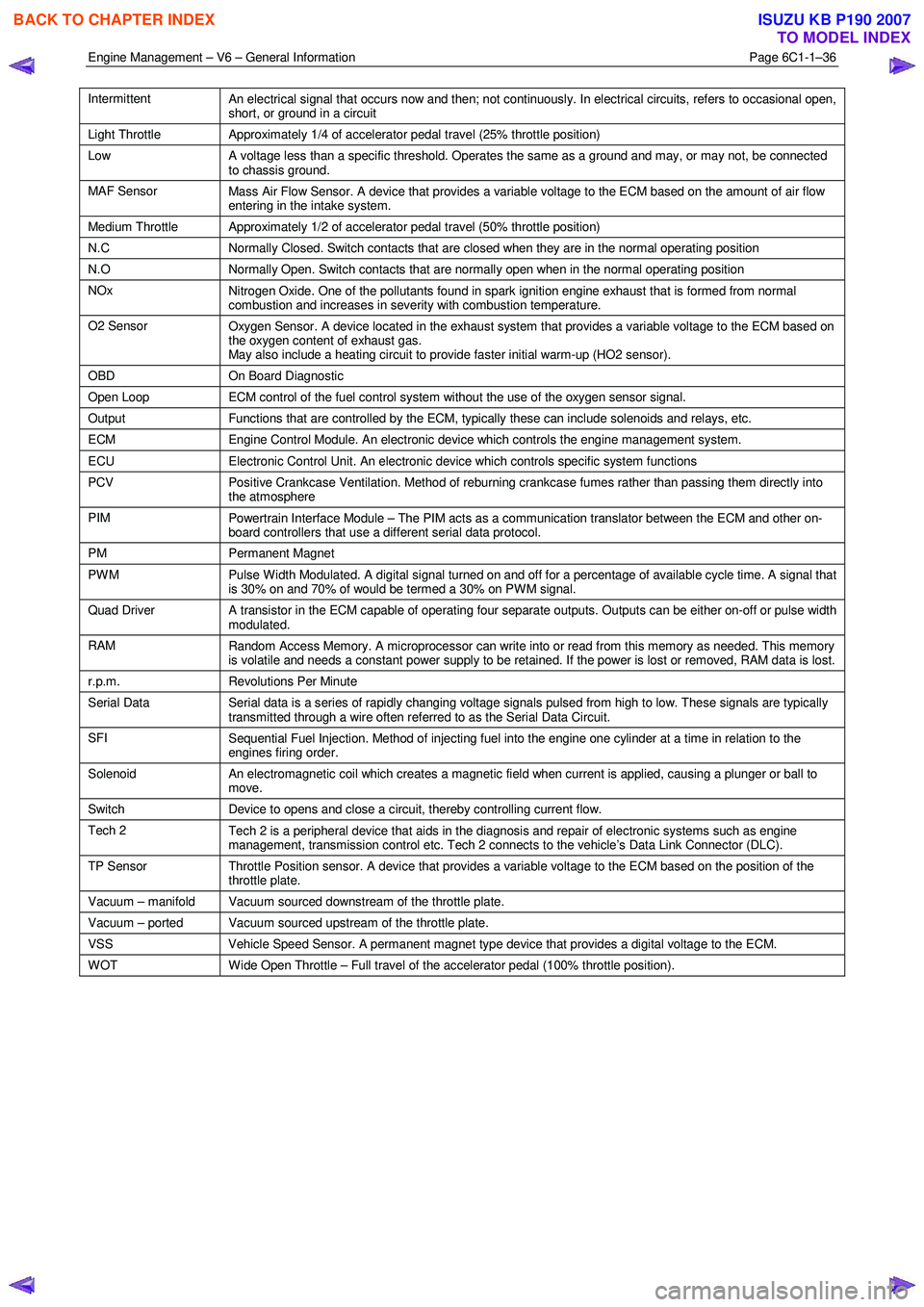
MAF Sensor Mass Air Flow Sensor. A device that provides a variable voltage to the ECM based on the amount of air flow
entering in the intake system.
Medium Throttle Approximately 1/2 of accelerator pedal travel (50% throttle position)
N.C Normally Closed. Switch contacts that are closed when they are in the normal operating position
N.O Normally Open. Switch contacts that are normally open when in the normal operating position
NOx
Nitrogen Oxide. One of the pollutants found in spark ignition engine exhaust that is formed from normal
combustion and increases in severity with combustion temperature.
O2 Sensor Oxygen Sensor. A device located in the exhaust system that provides a variable voltage to the ECM based on
the oxygen content of exhaust gas.
May also include a heating circuit to provide faster initial warm-up (HO2 sensor).
OBD On Board Diagnostic
Open Loop ECM control of the fuel control system without the use of the oxygen sensor signal.
Output Functions that are controlled by the ECM, typically these can include solenoids and relays, etc.
ECM Engine Control Module. An electronic device which controls the engine management system.
ECU Electronic Control Unit. An electronic device which controls specific system functions
PCV
Positive Crankcase Ventilation. Method of reburning crankcase fumes rather than passing them directly into
the atmosphere
PIM Powertrain Interface Module – The PIM acts as a communication translator between the ECM and other on-
board controllers that use a different serial data protocol.
PM Permanent Magnet
PWM
Pulse Width Modulated. A digital signal turned on and off for a percentage of available cycle time. A signal that
is 30% on and 70% of would be termed a 30% on PWM signal.
Quad Driver A transistor in the ECM capable of operating four separate outputs. Outputs can be either on-off or pulse width
modulated.
RAM Random Access Memory. A microprocessor can write into or read from this memory as needed. This memory
is volatile and needs a constant power supply to be retained. If the power is lost or removed, RAM data is lost.
r.p.m. Revolutions Per Minute
Serial Data
Serial data is a series of rapidly changing voltage signals pulsed from high to low. These signals are typically
transmitted through a wire often referred to as the Serial Data Circuit.
SFI Sequential Fuel Injection. Method of injecting fuel into the engine one cylinder at a time in relation to the
engines firing order.
Solenoid An electromagnetic coil which creates a magnetic field when current is applied, causing a plunger or ball to
move.
Switch Device to opens and close a circuit, thereby controlling current flow.
Tech 2
Tech 2 is a peripheral device that aids in the diagnosis and repair of electronic systems such as engine
management, transmission control etc. Tech 2 connects to the vehicle’s Data Link Connector (DLC).
TP Sensor Throttle Position sensor. A device that provides a variable voltage to the ECM based on the position of the
throttle plate.
Vacuum – manifold Vacuum sourced downstream of the throttle plate.
Vacuum – ported Vacuum sourced upstream of the throttle plate.
VSS Vehicle Speed Sensor. A permanent magnet type device that provides a digital voltage to the ECM.
WOT Wide Open Throttle – Full travel of the accelerator pedal (100% throttle position).
BACK TO CHAPTER INDEX
TO MODEL INDEX
ISUZU KB P190 2007
Page 3298 of 6020
Engine Management – V6 – Diagnostics Page 6C1-2–20
• Ensure the resistance between the ECM housing and the battery negative cable is less than 0.5 Ω.
• Check the ECM bracket fasteners for correct torque value.
• Check all engine management related components for correct installation.
• Inspect the vacuum hoses for splits, kinks, oil contamination and proper connections, refer to the vehicle emission
control information label. Check the hoses thoroughly for any type of leak or restriction.
• Inspect the air intake ducts for being collapsed, split or for having damaged areas.
• Inspect for air leaks at the throttle body mounting area, mass air flow (MAF) sensor, intake manifold and intake
manifold sealing surfaces.
• Check for wiring harness routing that may be positioned too close to a high voltage or high current device such as
the following:
− Secondary ignition components, and
− Motors and generators.
NOTE
High voltage or high current devices may induce
electrical noise on a circuit, which can interfere
with normal circuit operation.
4.4 Diagnostic System Check
Description
The engine management diagnostic procedure is organised in a logical structure that begins with the Diagnostic System
Check. The Diagnostic System Check directs the diagnostic procedure to the logical steps necessary to diagnose an
engine driveability fault condition.
Test Description
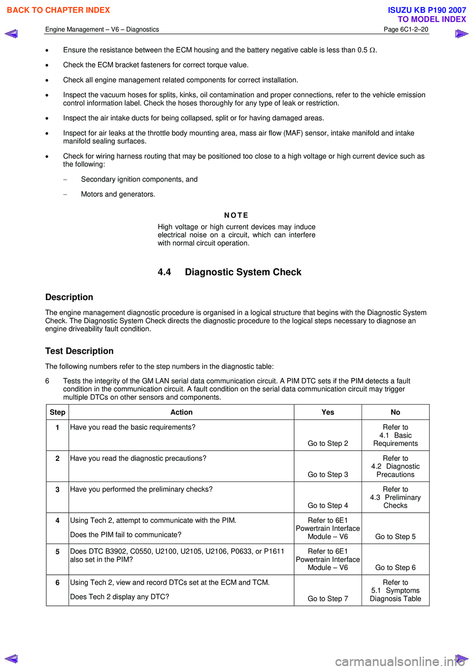
The following numbers refer to the step numbers in the diagnostic table:
6 Tests the integrity of the GM LAN serial data communication circuit. A PIM DTC sets if the PIM detects a fault condition in the communication circuit. A fault condition on the serial data communication circuit may trigger
multiple DTCs on other sensors and components.
Step Action Yes No
1 Have you read the basic requirements?
Go to Step 2 Refer to
4.1 Basic
Requirements
2 Have you read the diagnostic precautions?
Go to Step 3 Refer to
4.2 Diagnostic Precautions
3 Have you performed the preliminary checks?
Go to Step 4 Refer to
4.3 Preliminary Checks
4 Using Tech 2, attempt to communicate with the PIM.
Does the PIM fail to communicate? Refer to 6E1
Powertrain Interface Module – V6 Go to Step 5
5 Does DTC B3902, C0550, U2100, U2105, U2106, P0633, or P1611
also set in the PIM? Refer to 6E1
Powertrain Interface Module – V6 Go to Step 6
6 Using Tech 2, view and record DTCs set at the ECM and TCM.
Does Tech 2 display any DTC? Go to Step 7 Refer to
5.1 Symptoms
Diagnosis Table
BACK TO CHAPTER INDEX
TO MODEL INDEX
ISUZU KB P190 2007
Page 3322 of 6020
Engine Management – V6 – Diagnostics Page 6C1-2–44
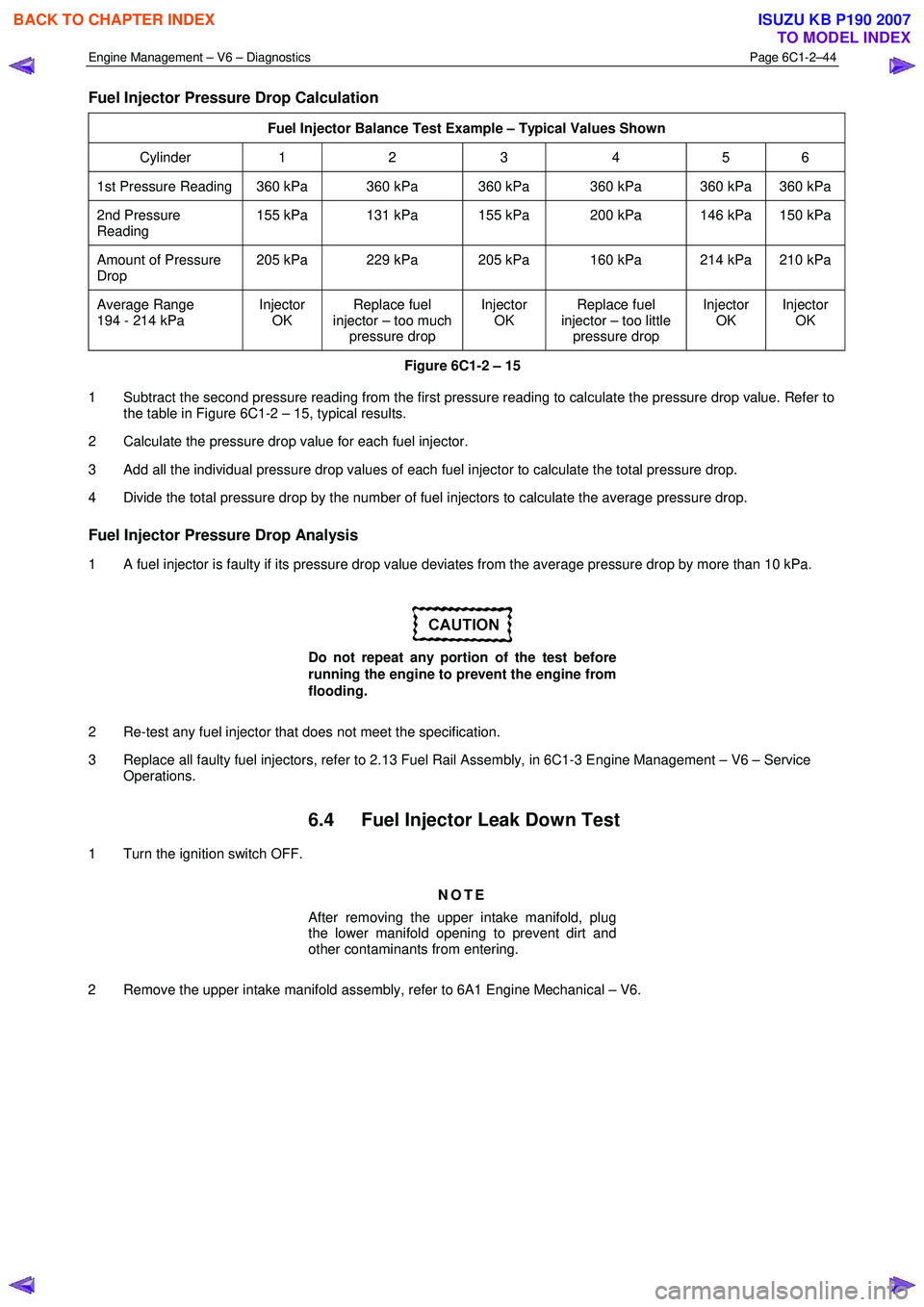
Fuel Injector Pressure Drop Calculation
Fuel Injector Balance Test Example – Typical Values Shown
Cylinder 1 2 3 4 5 6
1st Pressure Reading 360 kPa 360 kPa 360 kPa 360 kPa 360 kPa 360 kPa
2nd Pressure
Reading 155 kPa 131 kPa 155 kPa 200 kPa 146 kPa 150 kPa
Amount of Pressure
Drop 205 kPa 229 kPa 205 kPa 160 kPa 214 kPa 210 kPa
Average Range
194 - 214 kPa Injector
OK Replace fuel
injector – too much pressure drop Injector
OK Replace fuel
injector – too little pressure drop Injector
OK Injector
OK
Figure 6C1-2 – 15
1 Subtract the second pressure reading from the first pressure reading to calculate the pressure drop value. Refer to the table in Figure 6C1-2 – 15, typical results.
2 Calculate the pressure drop value for each fuel injector.
3 Add all the individual pressure drop values of each fuel injector to calculate the total pressure drop.
4 Divide the total pressure drop by the number of fuel injectors to calculate the average pressure drop.
Fuel Injector Pressure Drop Analysis
1 A fuel injector is faulty if its pressure drop value deviates from the average pressure drop by more than 10 kPa.
Do not repeat any portion of the test before
running the engine to prevent the engine from
flooding.
2 Re-test any fuel injector that does not meet the specification.
3 Replace all faulty fuel injectors, refer to 2.13 Fuel Rail Assembly, in 6C1-3 Engine Management – V6 – Service Operations.
6.4 Fuel Injector Leak Down Test
1 Turn the ignition switch OFF.
NOTE
After removing the upper intake manifold, plug
the lower manifold opening to prevent dirt and
other contaminants from entering.
2 Remove the upper intake manifold assembly, refer to 6A1 Engine Mechanical – V6.
BACK TO CHAPTER INDEX
TO MODEL INDEX
ISUZU KB P190 2007
Page 3324 of 6020
Engine Management – V6 – Diagnostics Page 6C1-2–46
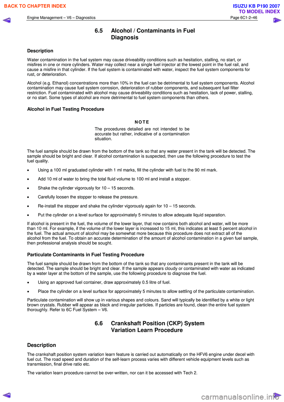
6.5 Alcohol / Contaminants in Fuel
Diagnosis
Description
W ater contamination in the fuel system may cause driveability conditions such as hesitation, stalling, no start, or
misfires in one or more cylinders. W ater may collect near a single fuel injector at the lowest point in the fuel rail, and
cause a misfire in that cylinder. If the fuel system is contaminated with water, inspect the fuel system components for
rust, or deterioration.
Alcohol (e.g. Ethanol) concentrations more than 10% in the fuel can be detrimental to fuel system components. Alcohol
contamination may cause fuel system corrosion, deterioration of rubber components, and subsequent fuel filter
restriction. Fuel contaminated with alcohol may cause driveability conditions such as hesitation, lack of power, stalling,
or no start. Some types of alcohol are more detrimental to fuel system components than others.
Alcohol in Fuel Testing Procedure
NOTE
The procedures detailed are not intended to be
accurate but rather, indicative of a contamination
situation.
The fuel sample should be drawn from the bottom of the tank so that any water present in the tank will be detected. The
sample should be bright and clear. If alcohol contamination is suspected, then use the following procedure to test the
fuel quality.
• Using a 100 ml graduated cylinder with 1 ml marks, fill the cylinder with fuel to the 90 ml mark.
• Add 10 ml of water to bring the total fluid volume to 100 ml and install a stopper.
• Shake the cylinder vigorously for 10 – 15 seconds.
• Carefully loosen the stopper to release the pressure.
• Re-install the stopper and shake the cylinder vigorously again for 10 – 15 seconds.
• Put the cylinder on a level surface for approximately 5 minutes to allow adequate liquid separation.
If alcohol is present in the fuel, the volume of the lower layer, that now contains both alcohol and water, will be more
than 10 ml. For example, if the volume of the lower layer is increased to 15 ml, this indicates at least 5 percent alcohol in
the fuel. The actual amount of alcohol may be somewhat more because this procedure does not extract all of the
alcohol from the fuel. To obtain an accurate determination of the amount of alcohol contamination in a given fuel sample,
then professional analysis should be sought.
Particulate Contaminants in Fuel Testing Procedure
The fuel sample should be drawn from the bottom of the tank so that any contaminants present in the tank will be
detected. The sample should be bright and clear. If the sample appears cloudy or contaminated with water as indicated
by a water layer at the bottom of the sample, use the following procedure to diagnose the fuel.
• Using an approved fuel container, draw approximately 0.5 litre of fuel.
• Place the cylinder on a level surface for approximately 5 minutes to allow settling of the particulate contamination.
Particulate contamination will show up in various shapes and colours. Sand will typically be identified by a white or light
brown crystals. Rubber will appear as black and irregular particles. If particles are found, clean the entire fuel system
thoroughly. Refer to 6C Fuel System – V6.
6.6 Crankshaft Position (CKP) System
Variation Learn Procedure
Description
The crankshaft position system variation learn feature is carried out automatically on the HFV6 engine under decel with
fuel cut. The road speed and duration of the self-learn process varies with different vehicle equipment levels such as
transmission, final drive ratio etc.
The variation learn procedure cannot be over-written, nor can it be accessed with Tech 2.
BACK TO CHAPTER INDEX
TO MODEL INDEX
ISUZU KB P190 2007
Page 3354 of 6020
Engine Management – V6 – Diagnostics Page 6C1-2–76
Conditions for Setting the DTC
DTC P0116
The ECM detects the engine coolant temperature sensor value is 10°C less than the minimum calculated engine
temperature.
DTC P0117
The ECM detects the engine coolant temperature is greater than 140 °C for longer than 3 seconds.
DTC P0118
The ECM detects the engine coolant temperature is less than -39 °C for longer than 3 seconds.
DTC P0125
The ECM determines the calculated engine temperature by measuring the amount of airflow into the engine. This DTC
sets if the ECM detects the actual ECT sensor is not within 10ºC of the calculated engine temperature for approximately
2 – 5 minutes.
DTC P1258
The ECM detects the engine coolant temperature is greater than 131 °C for longer than 2 seconds.
Conditions for Clearing the DTC
The ECT sensor DTCs are Type B DTCs. Refer to 1.4 Diagnostic Trouble Codes in this Section, for action taken when a
Type B DTC sets and conditions for clearing Type B DTC.
Additional Information
• Refer to 6C1-1 Engine Management – V6 – General Information for details of the ECT sensor operation.
• For an intermittent fault condition, refer to 5.2 Intermittent Fault Conditions in this Section.
• DTCs P0116, P0117, P0118 and P0125 diagnostic table is developed with the assumption the engine cooling
system is functioning correctly. Therefore, rectify any engine cooling system fault conditions before proceeding
with this diagnostic table.
• Test the ECT sensor using the ECT Temperature vs. Resistance in 6C1-3 Engine Management –V6 – Service
Operations. If the engine has sat overnight, the ECT sensor should display within 3 °C of the IAT sensor values.
W hen the engine is first started, the ECT should rise steadily to about 90 °C then stabilise when thermostat opens.
• Since fault condition in a wiring connector may trigger DTCs, always test the connectors related to this diagnostic
procedure for shorted terminals or poor wiring connection before replacing any component. Refer to 8A Electrical -
Body and Chassis for information on electrical fault diagnosis.
• To assist diagnosis, refer to 3 W iring Diagrams and Connector Charts in this Section, for the system wiring
diagram and connector charts.
Test Description
The following numbers refer to the step numbers in the diagnostic table:
2 A fault condition in the engine cooling system may trigger these DTCs.
7 The ECT sensor low reference circuit is shared with other components. DTC P0118 may set if the shared low reference circuit is shorted to voltage. Test the low reference circuit of all components that share this circuit to find
the source of the fault condition.
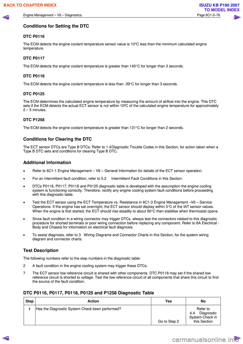
DTC P0116, P0117, P0118, P0125 and P1258 Diagnostic Table
Step Action Yes No
1 Has the Diagnostic System Check been performed?
Go to Step 2 Refer to
4.4 Diagnostic
System Check in this Section
BACK TO CHAPTER INDEX
TO MODEL INDEX
ISUZU KB P190 2007
Page 3366 of 6020
Engine Management – V6 – Diagnostics Page 6C1-2–88
• DTC P0153 – HO2S Circuit Slow Response – Bank 2 Sensor 1
Circuit Description
The wide band heated oxygen sensor (HO2S) measures the amount of oxygen in the exhaust system and provides
more information than the switching style HO2S. The wide band sensor consists of an oxygen sensing cell, an oxygen
pumping cell, and a heater.
The exhaust gas sample passes through a diffusion gap between the sensing cell and the pumping cell. The engine
control module (ECM) supplies a voltage to the HO2S and uses this voltage as a reference to the amount of oxygen in
the exhaust system. An electronic circuit within the ECM controls the pump current through the oxygen pumping cell to
maintain a constant voltage in the oxygen sensing cell. The ECM monitors the voltage variation in the sensing cell and
attempts to keep the voltage constant by increasing or decreasing the amount of current flow, or oxygen ion flow, to the
pumping cell.
By measuring the amount of current required to maintain the voltage in the sensing cell, the ECM can determine the
concentration of oxygen in the exhaust. The HO2S voltage is displayed as a lambda value. A lambda value of 1 is equal
to a stoichiometric air fuel ratio of 14.7:1. Under normal operating conditions, the lambda value will remain around 1.
W hen the fuel system is lean, the oxygen level will be high and the lambda signal will be high or more than 1. W hen the
fuel system is rich, the oxygen level will be low, and the lambda signal will be low or less than 1. The ECM uses this
information to maintain the correct air / fuel ratio.
Conditions for Running the DTC
• Before the ECM can report DTC P0133 or P0153 failed, DTCs P0121, P0122, P0123, P0221, P0222, P0223,
P0336, P0338, P2237, and P2240 must run and pass.
• DTCs P0030, P0031, P0032, P0050, P0051, P0052, P0053, P0059, P0130, P0131, P0132, P0135, P0150, P0151,
P0151, P0152, P0155, P0442, P0443, P0446, P0455, P0458, P0459, P0496, P167A, P167B, P2096, P2097,
P2098, P2099, P2231, P2234, P2243, P2247, P2251, P2254, P2297, P2298, P2626, and P2629 are not set.
• The HO2S is at operating temperature.
• The HO2S is between 0.94 – 1.06 lambda.
• The engine speed is between 1,480 – 2,040 rpm.
• The volumetric efficiency is between 16.5 – 38.3 percent.
• The change in volumetric efficiency is less than 3 percent.
• The evaporative emission (EVAP) purge is not active, or the ECM determines the EVAP hydrocarbon (HC)
concentration is less than a predetermined amount when EVAP purge is active.
• The long term fuel trim correction is active.
• DTCs P0133 and P0153 run continuously once the above conditions are met for 10 minutes.
Conditions for Setting the DTC
• The ECM has determined that the dynamic value of the affected HO2S is less than a predetermined threshold.
• The above condition is met for more than 4 seconds.
Action Taken When the DTC Sets
• The ECM illuminates the malfunction indicator lamp (MIL) on the second consecutive ignition cycle that the
diagnostic runs and fails.
• The control module records the operating conditions at the time the diagnostic fails. The first time the diagnostic
fails, the control module stores this information in the Failure Records. If the diagnostic reports a failure on the
second consecutive ignition cycle, the control module records the operating conditions at the time of the failure.
The control module writes the operating conditions to the Freeze Frame and updates the Failure Records.
Conditions for Clearing the MIL/DTC
• The ECM turns OFF the malfunction indicator lamp (MIL) after four consecutive ignition cycles that the diagnostic
runs and does not fail.
• A current DTC, Last Test Failed, clears when the diagnostic runs and passes.
BACK TO CHAPTER INDEX
TO MODEL INDEX
ISUZU KB P190 2007
Page 3372 of 6020
Engine Management – V6 – Diagnostics Page 6C1-2–94
9 1 The HO2S is detecting a rich or lean exhaust
condition or may be contaminated. Inspect for
one of the following conditions:
• HO2S connector water intrusion.
• A silicon-contaminated HO2S.
• Fuel-contaminated engine oil – refer to 6.5
Alcohol / Contaminants in Fuel
Diagnosis.
• Rich fuel injectors.
• Lean fuel injectors. Refer to 6C Fuel
System – V6
• An exhaust leak between the HO2S and
the engine. Refer to 6F Exhaust System –
V6.
• Vacuum leaks.
• Fuel contamination. W ater, even in small
amounts, can be delivered to the fuel
injectors, causing a lean exhaust to be
indicated. Excessive alcohol in the fuel can
also cause this condition. Refer to 6.5
Alcohol / Contaminants in Fuel
Diagnosis in this Section.
• An inaccurate mass air flow (MAF) sensor.
2 Repair any of the above or similar engine conditions, as necessary.
Did you find and correct the condition? —
Go to Step 15 Go to Step 10
10 1 Test for intermittent and poor connections at the
HO2S. Refer to 8A Electrical-Body and Chassis.
Did you find and correct the condition? —
Go to Step 15 Go to Step 13
11 1 Test for intermittent and poor connections at the
engine control module (ECM). Refer to 6C1-3
Engine Management – V6 – Service Operations.
Did you find and correct the condition? —
Go to Step 15 Go to Step 14
12 1 Repair the circuit with high resistance. Refer to
8A Electrical-Body and Chassis.
Did you complete the repair? —
Go to Step 15 —
13 1 Replace the affected HO2S. Refer to 6C1-3
Engine Management – V6 – Service Operations.
Did you complete the replacement? —
Go to Step 15 —
14 1 Replace the ECM. Refer to 6C1-3 Engine
Management – V6 – Service Operations.
Did you complete the replacement? —
Go to Step 15 —
15 1 Use Tech 2 to clear the DTCs.
2 Turn OFF the ignition for 30 seconds.
3 Start the engine.
4 Operate the vehicle within the Conditions for Running the DTC. You may also operate the
vehicle within the conditions that you observed
from the Freeze Frame / Failure Records.
Did the DTC fail this ignition? —
Go to Step 2 Go to Step 16
BACK TO CHAPTER INDEX
TO MODEL INDEX
ISUZU KB P190 2007