2007 ISUZU KB P190 engine mount
[x] Cancel search: engine mountPage 3150 of 6020
Engine Cooling – V6 Engine Page 6B1–15
2.8 Engine Coolant Temperature Sensor
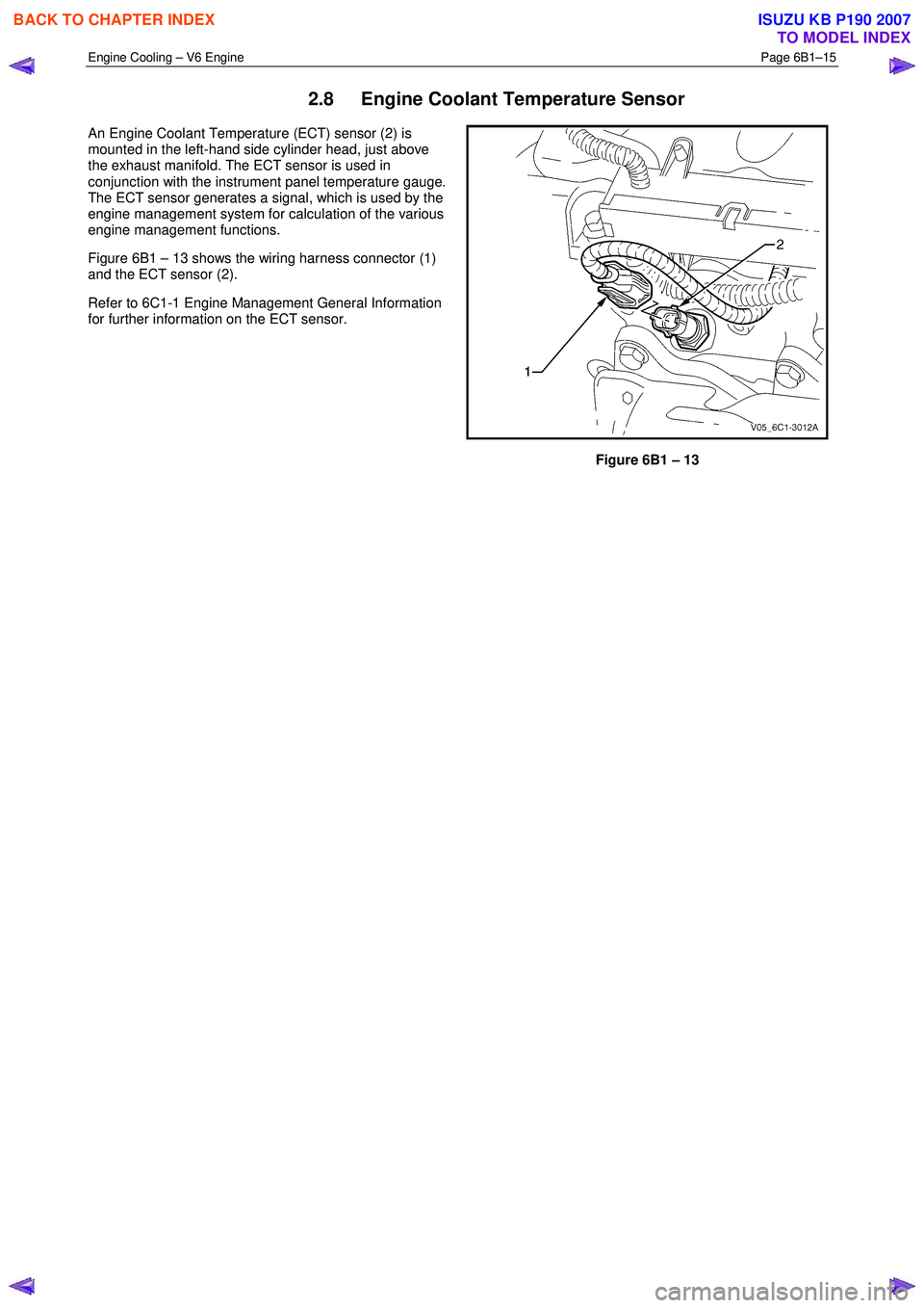
An Engine Coolant Temperature (ECT) sensor (2) is
mounted in the left-hand side cylinder head, just above
the exhaust manifold. The ECT sensor is used in
conjunction with the instrument panel temperature gauge.
The ECT sensor generates a signal, which is used by the
engine management system for calculation of the various
engine management functions.
Figure 6B1 – 13 shows the wiring harness connector (1)
and the ECT sensor (2).
Refer to 6C1-1 Engine Management General Information
for further information on the ECT sensor.
Figure 6B1 – 13
BACK TO CHAPTER INDEX
TO MODEL INDEX
ISUZU KB P190 2007
Page 3155 of 6020
Engine Cooling – V6 Engine Page 6B1–20
COOLANT CONCENTRATION
Litres Of Coolant To Be Added
Concentration Reading % Automatic Transmission Manual Transmission
0 4.95 5.15
5 4.46 4.62
10 3.96 4.12
15 3.47 3.61
20 2.97 3.08
25 2.48 2.57
30 1.98 2.01
35 1.48 1.54
40 0.99 1.05
45 0.50 0.52
50 0 0
NOTE
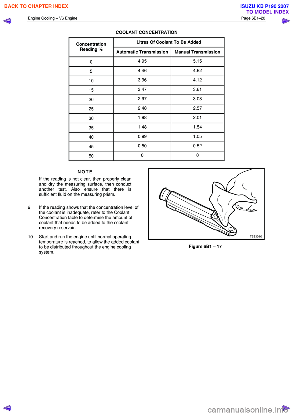
If the reading is not clear, then properly clean
and dry the measuring surface, then conduct
another test. Also ensure that there is
sufficient fluid on the measuring prism.
9 If the reading shows that the concentration level of the coolant is inadequate, refer to the Coolant
Concentration table to determine the amount of
coolant that needs to be added to the coolant
recovery reservoir.
10 Start and run the engine until normal operating temperature is reached, to allow the added coolant
to be distributed throughout the engine cooling
system.
Figure 6B1 – 17
BACK TO CHAPTER INDEX
TO MODEL INDEX
ISUZU KB P190 2007
Page 3156 of 6020
Engine Cooling – V6 Engine Page 6B1–21
Calibrating the Tester
The coolant tester calibration is checked at manufacture. If however, the calibration check detailed in Step 1 of this
method shows that the instrument is not reading correctly, then conduct the following recalibration procedure:
1 Remove the sealant covering the adjustment screw on the underneath of the tester.
2 W ith a distilled water sample on the measuring surface, carefully adjust the screw until a zero reading is obtained.
NOTE
DO NOT completely remove the screw.
3 After recalibration, reseal the screw with a small amount of silicone sealant.
Method 2 – Hydrometer
1 The cooling system should be at or close to ambient temperature.
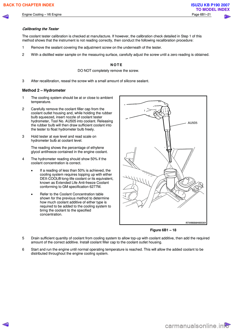
2 Carefully remove the coolant filler cap from the coolant outlet housing and, while holding the rubber
bulb squeezed, insert nozzle of coolant tester
hydrometer, Tool No. AU505 into coolant. Releasing
the rubber bulb will then draw sufficient coolant into
the tester to float hydrometer bulb freely.
3 Hold tester at eye level and read scale on hydrometer bulb at coolant level.
The reading shows the percentage of ethylene glycol antifreeze contained in the engine coolant.
4 The hydrometer reading should show 50% if the coolant concentration is correct.
• If a reading of less than 50% is achieved, the
cooling system requires topping up with either
DEX-COOL® long-life coolant or its equivalent,
known as Extended Life Anti-freeze Coolant
conforming to GM specification 6277M.
• Refer to the Coolant Concentration table
shown for the previous method to determine
how much coolant additive of either type is
required to be added to the cooling system to
bring the coolant to the specified
concentration.
Figure 6B1 – 18
5 Drain sufficient quantity of coolant from cooling system to allow top-up with coolant additive, then add the required amount of the correct additive. Install coolant filler cap to the coolant outlet housing.
6 Start and run the engine until normal operating temperature is reached. This will allow the added coolant to be distributed throughout the engine cooling system.
BACK TO CHAPTER INDEX
TO MODEL INDEX
ISUZU KB P190 2007
Page 3163 of 6020
Engine Cooling – V6 Engine Page 6B1–28
3.5 Drive Belt Tension
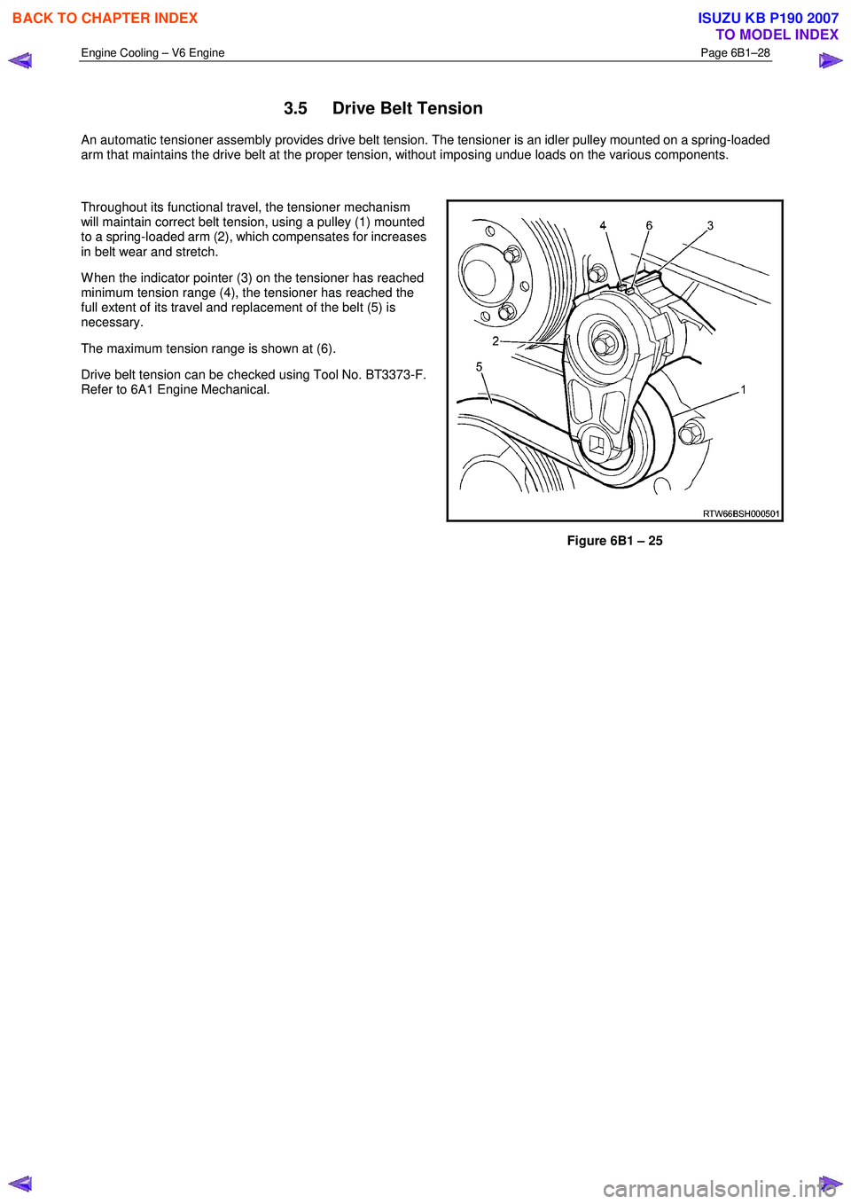
An automatic tensioner assembly provides drive belt tension. The tensioner is an idler pulley mounted on a spring-loaded
arm that maintains the drive belt at the proper tension, without imposing undue loads on the various components.
Throughout its functional travel, the tensioner mechanism
will maintain correct belt tension, using a pulley (1) mounted
to a spring-loaded arm (2), which compensates for increases
in belt wear and stretch.
W hen the indicator pointer (3) on the tensioner has reached
minimum tension range (4), the tensioner has reached the
full extent of its travel and replacement of the belt (5) is
necessary.
The maximum tension range is shown at (6).
Drive belt tension can be checked using Tool No. BT3373-F.
Refer to 6A1 Engine Mechanical.
Figure 6B1 – 25
BACK TO CHAPTER INDEX
TO MODEL INDEX
ISUZU KB P190 2007
Page 3190 of 6020
Engine Cooling – V6 Engine Page 6B1–55
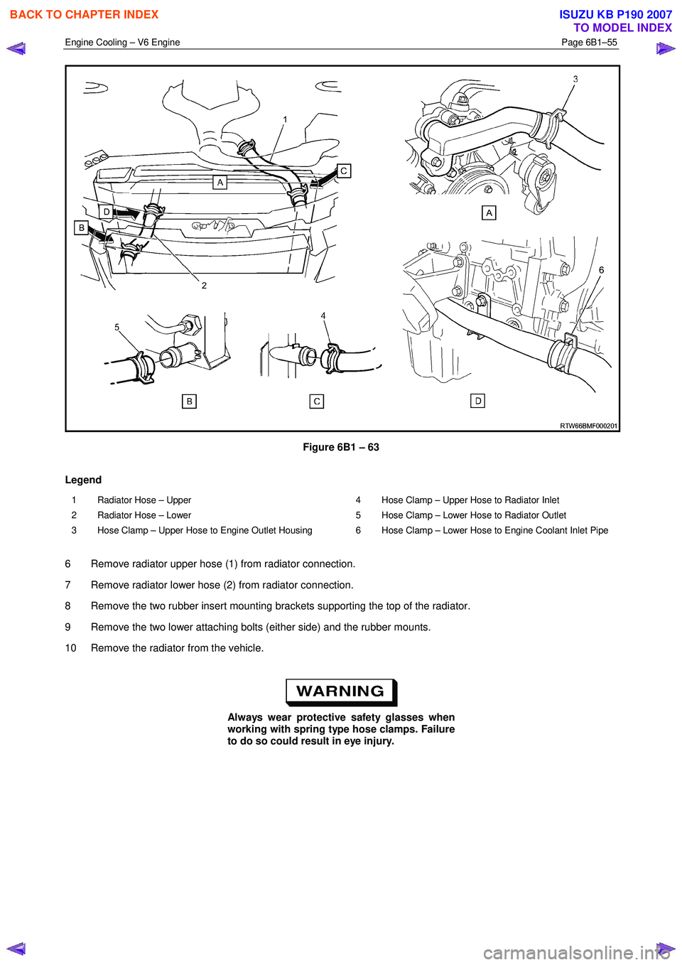
Figure 6B1 – 63
Legend
1 Radiator Hose – Upper
2 Radiator Hose – Lower
3 Hose Clamp – Upper Hose to Engine Outlet Housing 4 Hose Clamp – Upper Hose to Radiator Inlet
5 Hose Clamp – Lower Hose to Radiator Outlet
6 Hose Clamp – Lower Hose to Engine Coolant Inlet Pipe
6 Remove radiator upper hose (1) from radiator connection.
7 Remove radiator lower hose (2) from radiator connection.
8 Remove the two rubber insert mounting brackets supporting the top of the radiator.
9 Remove the two lower attaching bolts (either side) and the rubber mounts.
10 Remove the radiator from the vehicle.
Always wear protective safety glasses when
working with spring type hose clamps. Failure
to do so could result in eye injury.
BACK TO CHAPTER INDEX
TO MODEL INDEX
ISUZU KB P190 2007
Page 3194 of 6020
Engine Cooling – V6 Engine Page 6B1–59
General Core Repair
NOTE
The need for careful preparation of the surface in
the repair area cannot be over-emphasised. If the
leak area surface is not clean, the repair material
will not adhere to the surface.
Refer to ‘
‘‘
‘
Environmental Issues ’
’’
’
in 3.1
Service Notes, before draining the coolant.
1 Drain the coolant from the system. Refer to 3.3 Draining and Filling Cooling System in this Section.
2 Remove the radiator. Refer to 3.15 Radiator in this Section.
3 If necessary, carefully cut away fins to expose the damaged area.
NOTE
Do not cut away more than 25 mm total fin
material.
4 Clean away dirt etc. with water. Dry the affected area using hot air from a hair drier.
Do not apply flame to dry damaged area.
5 Clean affected area with petrol to remove any traces of oil.
6 Thoroughly stir contents of repair agent.
NOTE
In cases of extended shelf life, the silicon in
solution may separate from the thinner base.
Should this occur, mix contents well until agent is
again homogeneous.
7 Apply repair agent sparingly to damaged area. Do not apply an excessive amount, as this will cause blockage of the radiator tube.
NOTE
Use a clean, dry wooden applicator to 'DRIP'
agent onto damaged area of radiator.
8 Allow radiator to stand in a clean, dry area for a minimum of 3 hours (at ambient temperature of 20 – 30 ° C) with
adequate ventilation.
NOTE
Do not apply heat or flame to promote drying.
9 Reinstall the radiator. Refer to 3.15 Radiator in this Section.
BACK TO CHAPTER INDEX
TO MODEL INDEX
ISUZU KB P190 2007
Page 3196 of 6020
Engine Cooling – V6 Engine Page 6B1–61
4 Engine Cooling System
Diagnosis
4.1 Poor Heater Operation
Little or no heat coming from the heater, especially at idle could be an indication of a cooling system problem.
As the coolant level begins to get lower than normal, air enters the system to replace the missing coolant. The heater
core is one of the highest parts of the cooling system and therefore, the first area to lose coolant circulation.
At first, with a small amount of coolant loss, lack of heat will be most noticeable at idle. As driving speed increases, the
engine pumps more coolant and more heat is now able to pass through the heater core.
If coolant level drops even lower, heater operation will become less effective, even during normal driving. Cooling and
engine systems can be adversely affected if problem is not corrected before overheating occurs.
4.2 Leaking Cylinder Head Gasket
Combustion gases leaking past the cylinder head gasket can pressurise the cooling system, forcing coolant out of the
system and into the coolant recovery reservoir.
Indications are air bubbles in the coolant or an overflow condition of the recovery reservoir.
4.3 Question the Customer
To avoid needless time and cost in diagnosing cooling system complaints, the customer should be questioned about
driving conditions that place abnormal loads on the cooling system.
1 Is overheating occurring after prolonged idle, in gear, with air conditioning system operating?
If answer is YES – instruct owner on driving techniques that would avoid overheating such as:
• Idle in neutral as much as possible – increase engine rpm to get higher air flow (due to an increase in voltage
to the fan) and coolant flow through the radiator
• Turn air conditioning system off during extended idling periods if overheating is indicated on temperature
gauge. Further diagnostic checks should not be required
2 Is overheating occurring after prolonged driving in slow city traffic, traffic jams, parades, etc?
If answer is YES, explain driving technique to the customer, that would avoid overheating – same as for prolonged idle – No.1. Further diagnostic checks should not be required.
4.4 Diagnostic Chart
If none of the above conditions apply, refer to the following Diagnosis Chart.
To effectively use this chart, question the customer to determine which of the following three categories apply to the
complaint:
1 If complaint is hot indication on temperature gauge.
W as temperature reading accompanied by boiling?
• If answer is YES, go to overheating on diagnosis chart
• If answer is NO, check temperature gauge and sender
2 If complaint is boiling – go to overheating on diagnosis chart.
3 If complaint is coolant loss. Determine if customer is filling the system correctly.
4 If incorrect filling is not the problem, go to coolant loss in the diagnosis chart.
BACK TO CHAPTER INDEX
TO MODEL INDEX
ISUZU KB P190 2007
Page 3198 of 6020
Engine Cooling – V6 Engine Page 6B1–63
4.5 Problems Not Requiring Disassembly of
Cooling System
1 Large obstructions blocking radiator or condenser airflow.
• Auxiliary oil coolers
• License plate
• Obstruction of radiator grille, for example, driving lights or mud
2 Loose, damaged or missing air chute side panels.
3 Missing or damaged air baffle.
4 Cracked or loose coolant recovery system hose.
5 Leaking heater component such as the heater core or water valve.
4.6 Problems Requiring Disassembly of Cooling System
1 Damaged cooling fan or faulty motor operation.
2 Pressure test cooling system.
3 Defective coolant pump.
• Eroded or broken impeller vanes
• Failed bearing or seal – check for shaft or bearing end play
4 Internally blocked radiator core.
5 Obstruction of coolant recovery system.
6 Internal system leaks.
• Head gaskets
• Cracked cylinder block
• Engine front cover
• Intake manifold gaskets
7 Blocked coolant passages in cylinder heads or block – remove cylinder heads and check.
4.7 Black Light and Dye Leak Diagnosis Method
It is strongly recommended that this diagnostic method be used to diagnose fluid leaks. This method is a proven and
reliable method that identifies the specific leak source.
The black light kit can be used for the leak detection of a number of fluids, when used with the appropriate tracer dye.
Examples are: Coolant, Engine Oil, Automatic Transmission Fluid and Air Conditioning Refrigerant (R134A).
The following is a summary of the steps involved in detecting a cooling system fluid leak using black light and dye:
1 Pour specified amount of dye into the cooling system via the coolant filler cap on the outlet housing. Refer 3.1 Service Notes in this Section.
2 Road test the vehicle under normal operating conditions.
3 Direct the light towards the suspect area. The fluid leak will appear as a brightly coloured path leading from the source.
4 Repair fluid leak and recheck to ensure that leak has been rectified.
5 Refer to the manufacturer’s directions when using this method.
BACK TO CHAPTER INDEX
TO MODEL INDEX
ISUZU KB P190 2007