2007 ISUZU KB P190 engine mount
[x] Cancel search: engine mountPage 3205 of 6020
Fuel System – V6 Page 6C – 3
1 General Information
Description
Fuel is injected into the engine by separate fuel injectors that are mounted in the intake manifold (common chamber).
Fuel is supplied to the injectors under pressure from the fuel tank through the fuel lines and the fuel rail, which is
attached to the top of the common chamber.
A fuel pressure control valve is installed on the fuel rail to maintain fuel line pressure across the injectors under all
operating conditions. Fuel pressure is maintained by controlling the amount of fuel that is supplied from the fuel tank,
based on the demand of the engine via the engine control module (ECM).
Two interchangeable “O” rings are used on the fuel injector and must be replaced when the injectors are removed.
The Multiport Fuel Injection system utilizes an injection system where the injectors turn on at every crankshaft revolution.
The ECM controls the injector on time so that the correct amount of fuel is metered depending on driving conditions.
The V6 engine is designed to use only unleaded petrol.
Unleaded petrol must be used for correct emission control system operation and its use will also minimize spark plug
fouling and extend engine oil life.
Using leaded petrol can damage the emission control system and could void the vehicle warranty. All vehicles are
equipped with an Evaporative Emission Control System. The purpose of the system is to minimize the escape of fuel
vapours into the atmosphere.
Service Precautions
• Use extreme care when working on the fuel system and follow all safety precautions.
• W hen working on the fuel system, disconnect the battery ground cable except for tests where battery voltage is
required.
• Always keep a dry chemical (class B) fire extinguisher near the work area.
• Relace all fuel lines and fittings with the same type of line and fitting as those removed.
• Clean and inspect “O” rings carefully and replace if required.
• Always depressurize the fuel lines before servicing any fuel system components.
• Do not attempt any repairs on the fuel system until, all warnings and instructions, relating to that repair have been
read and ensure all notices and cautions are adhered to.
• Do not allow any naked frames or sparks near the work area when working on the fuel system.
• If draining of the fuel system is required, this should be done in a well ventilated area.
• Protect the fuel lines and associated parts from thermal damage, spattering when welding.
BACK TO CHAPTER INDEX
TO MODEL INDEX
ISUZU KB P190 2007
Page 3209 of 6020
Fuel System – V6 Page 6C – 7
Fuel Flow
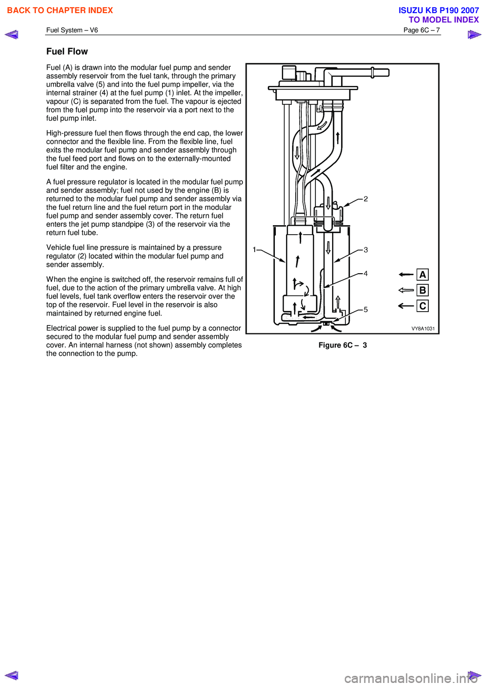
Fuel (A) is drawn into the modular fuel pump and sender
assembly reservoir from the fuel tank, through the primary
umbrella valve (5) and into the fuel pump impeller, via the
internal strainer (4) at the fuel pump (1) inlet. At the impeller,
vapour (C) is separated from the fuel. The vapour is ejected
from the fuel pump into the reservoir via a port next to the
fuel pump inlet.
High-pressure fuel then flows through the end cap, the lower
connector and the flexible line. From the flexible line, fuel
exits the modular fuel pump and sender assembly through
the fuel feed port and flows on to the externally-mounted
fuel filter and the engine.
A fuel pressure regulator is located in the modular fuel pump
and sender assembly; fuel not used by the engine (B) is
returned to the modular fuel pump and sender assembly via
the fuel return line and the fuel return port in the modular
fuel pump and sender assembly cover. The return fuel
enters the jet pump standpipe (3) of the reservoir via the
return fuel tube.
Vehicle fuel line pressure is maintained by a pressure
regulator (2) located within the modular fuel pump and
sender assembly.
W hen the engine is switched off, the reservoir remains full of
fuel, due to the action of the primary umbrella valve. At high
fuel levels, fuel tank overflow enters the reservoir over the
top of the reservoir. Fuel level in the reservoir is also
maintained by returned engine fuel.
Electrical power is supplied to the fuel pump by a connector
secured to the modular fuel pump and sender assembly
cover. An internal harness (not shown) assembly completes
the connection to the pump.
Figure 6C – 3
BACK TO CHAPTER INDEX
TO MODEL INDEX
ISUZU KB P190 2007
Page 3211 of 6020
Fuel System – V6 Page 6C – 9
A small amount of fuel may be released when
connecting the fuel pressure gauge to the fuel
pressure test point. Cover the fittings with a
shop towel to absorb any fuel spillage before
connecting the fuel pressure gauge. After the
fuel pressure test procedure, place the soiled
towel in an approved container for disposal.
3 At the fuel pressure test point, remove the Schrader valve sealing cap.
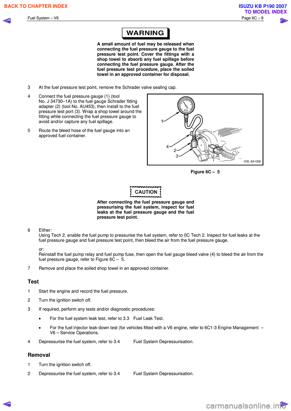
4 Connect the fuel pressure gauge (1) (tool No. J 34730–1A) to the fuel gauge Schrader fitting
adapter (2) (tool No. AU453), then install to the fuel
pressure test port (3). W rap a shop towel around the
fitting while connecting the fuel pressure gauge to
avoid and/or capture any fuel spillage.
5 Route the bleed hose of the fuel gauge into an approved fuel container.
Figure 6C – 5
After connecting the fuel pressure gauge and
pressurising the fuel system, inspect for fuel
leaks at the fuel pressure gauge and the fuel
pressure test point.
6 Either: Using Tech 2, enable the fuel pump to pressurise the fuel system, refer to 0C Tech 2. Inspect for fuel leaks at the
fuel pressure gauge and fuel pressure test point, then bleed the air from the fuel pressure gauge.
or: Reinstall the fuel pump relay and fuel pump fuse, then open the fuel gauge bleed valve (4) to bleed the air from the
fuel pressure gauge, refer to Figure 6C – 5.
7 Remove and place the soiled shop towel in an approved container.
Test
1 Start the engine and record the fuel pressure.
2 Turn the ignition switch off.
3 If required, perform any tests and/or diagnostic procedures:
• For the fuel system leak test, refer to 3.3 Fuel Leak Test.
• For the fuel injector leak-down test (for vehicles fitted with a V6 engine, refer to 6C1-3 Engine Management –
V6 – Service Operations.
4 Depressurise the fuel system, refer to 3.4 Fuel System Depressurisation.
Removal
1 Turn the ignition switch off.
2 Depressurise the fuel system, refer to 3.4 Fuel System Depressurisation.
BACK TO CHAPTER INDEX
TO MODEL INDEX
ISUZU KB P190 2007
Page 3212 of 6020
Fuel System – V6 Page 6C – 10
After relieving the fuel system pressure, a
small amount of fuel may be released when
servicing the fuel lines or connections. Cover
the fittings with a shop towel before
disconnecting. This catches any leaking fuel.
Place the soiled towel in an approved
container when disconnection is completed.
3 W rap a shop towel around the fuel pressure test point to absorb any fuel spillage.
4 Remove the fuel pressure gauge and drain any fuel remaining in the fuel pressure gauge into an approved fuel container.
5 Remove the soiled shop towel and place in an approved container.
6 Repressurise the fuel system, refer to 3.4 Fuel System Depressurisation.
7 Road-test the vehicle and check for correct operation.
3.3 Fuel Leak Test
After installing any fuel system component
and before starting the engine, check the fuel
system for leaks.
NOTE
For the fuel injector leak-down test (for vehicles
fitted with a V6 engine), refer to 6C1-3 Engine
Management – V6 – Service Operations.
1 Turn the ignition switch on for two seconds.
2 Turn the ignition switch off for 10 seconds.
3 Turn the ignition switch on.
4 Check for fuel leaks, particularly at points marked �z (that is, quick-connect fittings, fuel rails, fuel injectors,
Schrader valve and evaporative emission control canister purge solenoid, refer to Figure 6C – 6.
BACK TO CHAPTER INDEX
TO MODEL INDEX
ISUZU KB P190 2007
Page 3214 of 6020
Fuel System – V6 Page 6C – 12
A small amount of fuel may be released when
pressing on the Schrader valve. Cover the
fitting with a shop towel to absorb any fuel
spillage before removing the Schrader valve
sealing cap. Place the soiled towel in an
approved container for disposal.
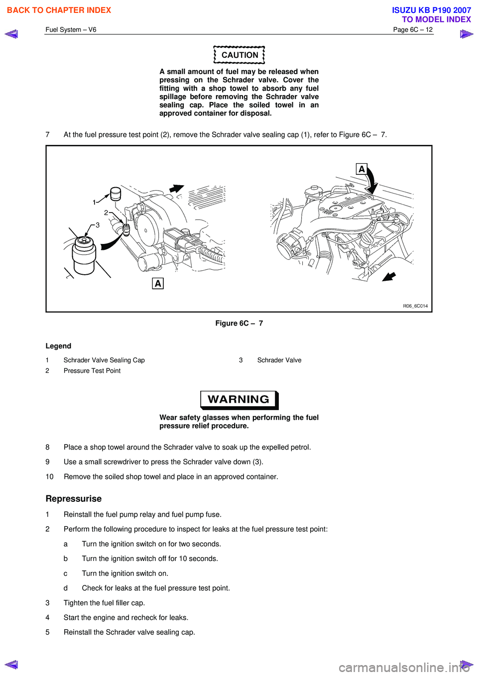
7 At the fuel pressure test point (2), remove the Schrader valve sealing cap (1), refer to Figure 6C – 7.
Figure 6C – 7
Legend
1 Schrader Valve Sealing Cap
2 Pressure Test Point 3 Schrader Valve
Wear safety glasses when performing the fuel
pressure relief procedure.
8 Place a shop towel around the Schrader valve to soak up the expelled petrol.
9 Use a small screwdriver to press the Schrader valve down (3).
10 Remove the soiled shop towel and place in an approved container.
Repressurise
1 Reinstall the fuel pump relay and fuel pump fuse.
2 Perform the following procedure to inspect for leaks at the fuel pressure test point: a Turn the ignition switch on for two seconds.
b Turn the ignition switch off for 10 seconds.
c Turn the ignition switch on.
d Check for leaks at the fuel pressure test point.
3 Tighten the fuel filler cap.
4 Start the engine and recheck for leaks.
5 Reinstall the Schrader valve sealing cap.
BACK TO CHAPTER INDEX
TO MODEL INDEX
ISUZU KB P190 2007
Page 3217 of 6020
Fuel System – V6 Page 6C – 15
Reinstall
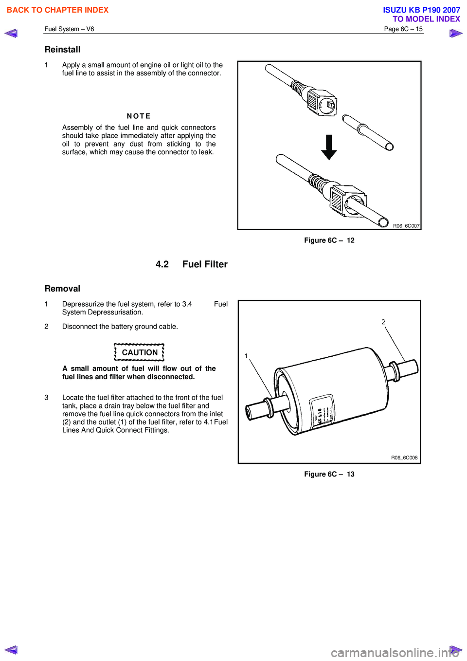
1 Apply a small amount of engine oil or light oil to the
fuel line to assist in the assembly of the connector.
NOTE
Assembly of the fuel line and quick connectors
should take place immediately after applying the
oil to prevent any dust from sticking to the
surface, which may cause the connector to leak.
Figure 6C – 12
4.2 Fuel Filter
Removal
1 Depressurize the fuel system, refer to 3.4 Fuel
System Depressurisation.
2 Disconnect the battery ground cable.
A small amount of fuel will flow out of the
fuel lines and filter when disconnected.
3 Locate the fuel filter attached to the front of the fuel tank, place a drain tray below the fuel filter and
remove the fuel line quick connectors from the inlet
(2) and the outlet (1) of the fuel filter, refer to 4.1 Fuel
Lines And Quick Connect Fittings.
Figure 6C – 13
BACK TO CHAPTER INDEX
TO MODEL INDEX
ISUZU KB P190 2007
Page 3252 of 6020
Engine Management – V6 – General Information Page 6C1-1–10
Fuel Injection System
Each cylinder of the V6 engine is fitted with one fuel injector. The engine control relay applies ignition positive voltage to
the fuel injector ignition circuit. The ECM controls the operation of the fuel injectors by applying a pulse width modulated
(PW M) ground to the fuel injector control circuit to control each fuel injector on-time.
W hile the engine is running, the ECM constantly monitors the various inputs and recalculates the appropriate on-time for
each injector. The calculation is based on the following:
• The injector flow rate,
• Mass of fuel passed by the energised injector per unit of time,
• The desired air / fuel ratio, and
• Actual air mass in each cylinder.
The ECM calculates the duration of the fuel injector on-time to deliver the correct amount of fuel for optimum drivability
and emission control. The period of time the fuel injector is energised is called the injector on-time and is measured in
milliseconds (thousandths of a second).
The V6 engine uses the sequential fuel injection system. Each fuel injector is energised individually at the correct
moment during its firing stroke as the cylinder’s intake valves are closing to provide enough time for the fuel to atomise
completely and mix with the intake air.
Short Term Fuel Trim
The short term fuel trim (STFT) represents the duration of the fuel injector on-time as calculated by the ECM, while the
ECM is in Closed Loop mode. The STFT allows the ECM to calculate the fuel injector on-time based on the heated
oxygen sensor (HO2S) signal input to the ECM. Therefore, the STFT is disabled when the ECM is in Open Loop mode.
• If the air / fuel mixture in the exhaust is balanced (lambda = 1) or when the STFT is disabled, the STFT value is 0%.
• W hen the HO2S sends an input signal to the ECM indicating the air / fuel mixture is rich, the STFT will be less than
0%, which indicates the ECM is decreasing the fuel injector on-time to reduce the amount of fuel in the air / fuel
mixture.
• W hen the HO2S sends an input signal to the ECM indicating the air / fuel mixture is lean, the STFT will be greater
than 0%, which indicates the ECM is increasing the fuel injector on-time to increase the amount of fuel in the air /
fuel mixture.
The percentage values of the STFT range from –25% to +25% and are directly proportional to the duration of the fuel
injector on-time.
Long Term Fuel Trim
The ECM stores the long term fuel trim (LTFT) in its memory to adjust the fuel injector on-time according to the long term
changes or deterioration in the engine components. The normal LTFT value is 0%.
The following describes the LTFT operation when the engine air filter is dirty that causes a restricted intake airflow fault
condition:
1 The HO2S sends an input signal to the ECM the air / fuel mixture is rich because of the reduced airflow. The STFT may reduce to a value of –10%, which decreases the fuel injector on-time to reduce the amount of fuel in the air /
fuel mixture supplied to the engine.
W ithout the use of the LTFT, the restricted airflow caused by the dirty air filter may reduce the STFT value to –10% until the air filter is replaced. This will decrease the range of negative adjustment available to the STFT to
compensate for other factors.
2 W hen the ECM detects the STFT has remained at –10% for a specific period, the ECM switches to the LTFT. The LTFT adjusts the duration of the fuel injector on-time until the air / fuel mixture in the exhaust is balanced (lambda =
1) and the STFT value returns to 0%.
3 The ECM stores this Long Term FT value in its memory, which is used to calculate the base fuel injector on-time.
The percentage values of the Long Term FT range from –100% to +100%. If the ECM detects the LTFT values are
outside the specified percentage range for a predetermined period, the ECM will set a Diagnostic Trouble Code and
switch to Open Loop mode.
BACK TO CHAPTER INDEX
TO MODEL INDEX
ISUZU KB P190 2007
Page 3253 of 6020
Engine Management – V6 – General Information Page 6C1-1–11
3.2 Air / Fuel Control System
The engine control module (ECM) controls the amount of air and fuel delivered into each of the engine cylinders. Based
on the various ECM inputs, the ECM switches to the following air / fuel control system mode to provide the optimum air /
fuel ratio under all engine operating conditions.
Starting Mode
W hen the ignition switch is moved to the START position and the engine begins to turn, a prime pulse may be injected to
speed starting. As soon as the ECM receives an input signal from the camshaft position (CMP) and crankshaft position
(CKP) sensor and determines which cylinder is in the firing stroke, the ECM applies a pulse width modulated (PW M)
ground to the injector control circuit. The ECM monitors mass air flow, intake air temperature, engine coolant
temperature, and throttle position to determine the required fuel injector on-time required for starting the engine.
Run Mode
The engine switches to run mode when the engine speed reaches 480 rpm after being started. The run mode has two
sub-modes called Open Loop and Closed Loop.
Open Loop Mode
The heated oxygen sensor (HO2S) does not produce a usable signal voltage output until it reaches operating
temperature. Therefore, while the HO2S is below its operating temperature, the ECM switches to open loop mode.
In open loop, the ECM ignores the signals from the HO2S and calculates the required injector pulse width based
primarily on inputs from the mass air flow (MAF), intake air temperature (IAT), and engine coolant temperature sensors.
The system will stay in the open loop mode until the HO2S produce a usable output.
Closed Loop Mode
Once the HO2S reaches operating temperature and starts producing its own signal voltage output, the ECM switches to
the closed loop mode.
In closed loop mode, the ECM initially calculates injector pulse width based on the same sensors used in open loop, and
additionally the ECM uses the oxygen sensor signals to modify and fine tune the fuel pulse width calculations to precisely
maintain the ideal 14.7 to 1 air / fuel ratio.
Acceleration Mode
The ECM monitors and calculates input signals from the accelerator pedal position (APP) and MAF sensor signals to
determine when the vehicle is being accelerated. If the ECM detects the accelerator pedal is depressed and there is a
demand for the vehicle to accelerate, the ECM switches to acceleration mode. In acceleration mode, the ECM increases
the fuel injector on-time to provide more fuel accordingly.
Deceleration Mode
The ECM monitors and calculates input signals from the APP and MAF sensor signals to determine when the vehicle is
being decelerated. If the ECM detects the vehicle is decelerating, the ECM switches to deceleration mode. In
deceleration mode, the ECM decreases the fuel injector on-time, or disables the fuel injectors for short periods, to reduce
exhaust emissions and improve fuel economy.
Fuel Shut-off Mode
To protect the engine from damage or to improve the vehicle's driveability, the ECM switches to the fuel shut-off mode. In
fuel shut-off mode, the ECM performs the following:
• The ECM disables the six fuel injectors under the following conditions:
− Ignition off – to prevent engine dieseling,
− Ignition on but no ignition reference signal – prevents flooding or backfiring,
− At high engine speed – greater than the red line (rev limiter),
− At high vehicle speed – greater than the rated tire speed (vehicle speed limiter), or
− Extended high speed closed throttle coast-down – reduces engine emissions and increases engine braking.
• The ECM selectively disables the appropriate number of fuel injectors when torque management has been enabled.
BACK TO CHAPTER INDEX
TO MODEL INDEX
ISUZU KB P190 2007