2007 ISUZU KB P190 engine mount
[x] Cancel search: engine mountPage 3389 of 6020
Engine Management – V6 – Diagnostics Page 6C1-2–111
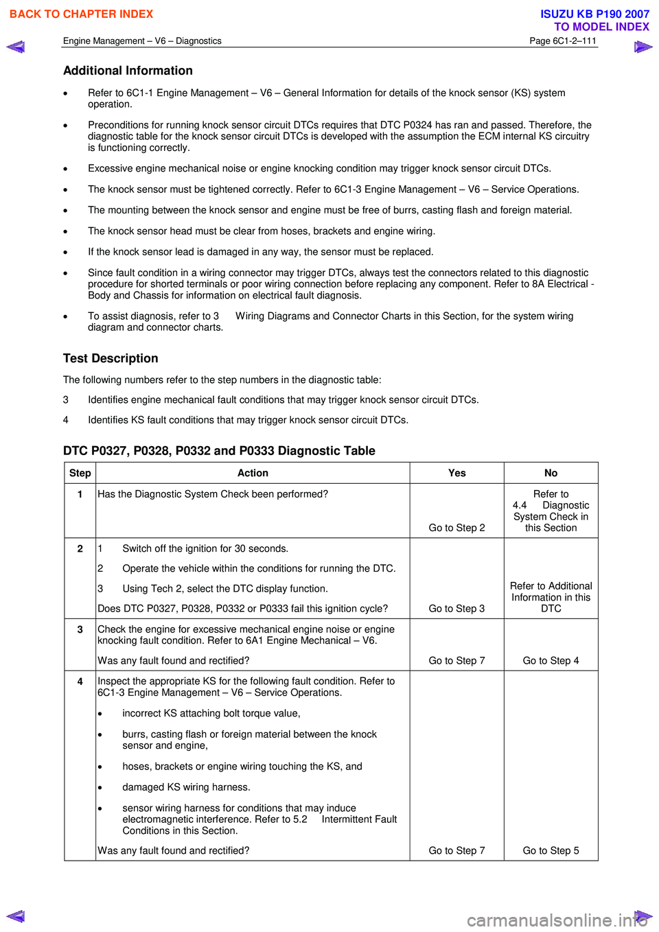
Additional Information
• Refer to 6C1-1 Engine Management – V6 – General Information for details of the knock sensor (KS) system
operation.
• Preconditions for running knock sensor circuit DTCs requires that DTC P0324 has ran and passed. Therefore, the
diagnostic table for the knock sensor circuit DTCs is developed with the assumption the ECM internal KS circuitry
is functioning correctly.
• Excessive engine mechanical noise or engine knocking condition may trigger knock sensor circuit DTCs.
• The knock sensor must be tightened correctly. Refer to 6C1-3 Engine Management – V6 – Service Operations.
• The mounting between the knock sensor and engine must be free of burrs, casting flash and foreign material.
• The knock sensor head must be clear from hoses, brackets and engine wiring.
• If the knock sensor lead is damaged in any way, the sensor must be replaced.
• Since fault condition in a wiring connector may trigger DTCs, always test the connectors related to this diagnostic
procedure for shorted terminals or poor wiring connection before replacing any component. Refer to 8A Electrical -
Body and Chassis for information on electrical fault diagnosis.
• To assist diagnosis, refer to 3 W iring Diagrams and Connector Charts in this Section, for the system wiring
diagram and connector charts.
Test Description
The following numbers refer to the step numbers in the diagnostic table:
3 Identifies engine mechanical fault conditions that may trigger knock sensor circuit DTCs.
4 Identifies KS fault conditions that may trigger knock sensor circuit DTCs.
DTC P0327, P0328, P0332 and P0333 Diagnostic Table
Step Action Yes No
1 Has the Diagnostic System Check been performed?
Go to Step 2 Refer to
4.4 Diagnostic System Check in this Section
2 1 Switch off the ignition for 30 seconds.
2 Operate the vehicle within the conditions for running the DTC.
3 Using Tech 2, select the DTC display function.
Does DTC P0327, P0328, P0332 or P0333 fail this ignition cycle? Go to Step 3 Refer to Additional
Information in this DTC
3 Check the engine for excessive mechanical engine noise or engine
knocking fault condition. Refer to 6A1 Engine Mechanical – V6.
W as any fault found and rectified? Go to Step 7 Go to Step 4
4 Inspect the appropriate KS for the following fault condition. Refer to
6C1-3 Engine Management – V6 – Service Operations.
• incorrect KS attaching bolt torque value,
• burrs, casting flash or foreign material between the knock
sensor and engine,
• hoses, brackets or engine wiring touching the KS, and
• damaged KS wiring harness.
• sensor wiring harness for conditions that may induce
electromagnetic interference. Refer to 5.2 Intermittent Fault
Conditions in this Section.
W as any fault found and rectified? Go to Step 7 Go to Step 5
BACK TO CHAPTER INDEX
TO MODEL INDEX
ISUZU KB P190 2007
Page 3448 of 6020
Engine Management – V6 – Diagnostics Page 6C1-2–170
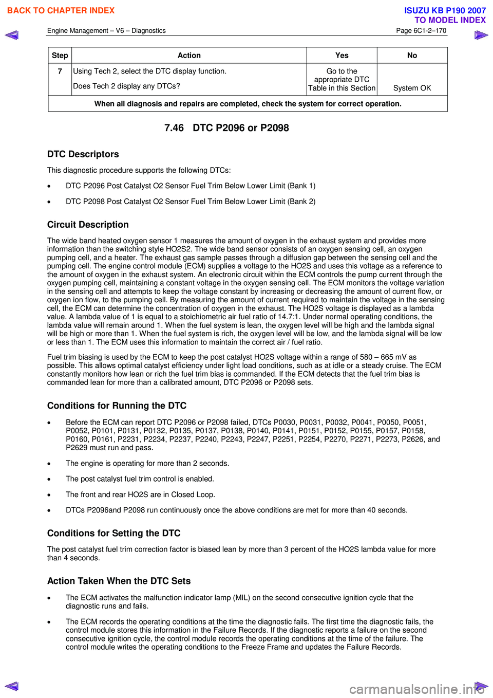
Step Action Yes
No
7 Using Tech 2, select the DTC display function.
Does Tech 2 display any DTCs? Go to the
appropriate DTC
Table in this Section System OK
When all diagnosis and repairs are completed, check the system for correct operation.
7.46 DTC P2096 or P2098
DTC Descriptors
This diagnostic procedure supports the following DTCs:
• DTC P2096 Post Catalyst O2 Sensor Fuel Trim Below Lower Limit (Bank 1)
• DTC P2098 Post Catalyst O2 Sensor Fuel Trim Below Lower Limit (Bank 2)
Circuit Description
The wide band heated oxygen sensor 1 measures the amount of oxygen in the exhaust system and provides more
information than the switching style HO2S2. The wide band sensor consists of an oxygen sensing cell, an oxygen
pumping cell, and a heater. The exhaust gas sample passes through a diffusion gap between the sensing cell and the
pumping cell. The engine control module (ECM) supplies a voltage to the HO2S and uses this voltage as a reference to
the amount of oxygen in the exhaust system. An electronic circuit within the ECM controls the pump current through the
oxygen pumping cell, maintaining a constant voltage in the oxygen sensing cell. The ECM monitors the voltage variation
in the sensing cell and attempts to keep the voltage constant by increasing or decreasing the amount of current flow, or
oxygen ion flow, to the pumping cell. By measuring the amount of current required to maintain the voltage in the sensing
cell, the ECM can determine the concentration of oxygen in the exhaust. The HO2S voltage is displayed as a lambda
value. A lambda value of 1 is equal to a stoichiometric air fuel ratio of 14.7:1. Under normal operating conditions, the
lambda value will remain around 1. W hen the fuel system is lean, the oxygen level will be high and the lambda signal
will be high or more than 1. W hen the fuel system is rich, the oxygen level will be low, and the lambda signal will be low
or less than 1. The ECM uses this information to maintain the correct air / fuel ratio.
Fuel trim biasing is used by the ECM to keep the post catalyst HO2S voltage within a range of 580 – 665 mV as
possible. This allows optimal catalyst efficiency under light load conditions, such as at idle or a steady cruise. The ECM
constantly monitors how lean or rich the fuel trim bias is commanded. If the ECM detects that the fuel trim bias is
commanded lean for more than a calibrated amount, DTC P2096 or P2098 sets.
Conditions for Running the DTC
• Before the ECM can report DTC P2096 or P2098 failed, DTCs P0030, P0031, P0032, P0041, P0050, P0051,
P0052, P0101, P0131, P0132, P0135, P0137, P0138, P0140, P0141, P0151, P0152, P0155, P0157, P0158,
P0160, P0161, P2231, P2234, P2237, P2240, P2243, P2247, P2251, P2254, P2270, P2271, P2273, P2626, and
P2629 must run and pass.
• The engine is operating for more than 2 seconds.
• The post catalyst fuel trim control is enabled.
• The front and rear HO2S are in Closed Loop.
• DTCs P2096and P2098 run continuously once the above conditions are met for more than 40 seconds.
Conditions for Setting the DTC
The post catalyst fuel trim correction factor is biased lean by more than 3 percent of the HO2S lambda value for more
than 4 seconds.
Action Taken When the DTC Sets
• The ECM activates the malfunction indicator lamp (MIL) on the second consecutive ignition cycle that the
diagnostic runs and fails.
• The ECM records the operating conditions at the time the diagnostic fails. The first time the diagnostic fails, the
control module stores this information in the Failure Records. If the diagnostic reports a failure on the second
consecutive ignition cycle, the control module records the operating conditions at the time of the failure. The
control module writes the operating conditions to the Freeze Frame and updates the Failure Records.
BACK TO CHAPTER INDEX
TO MODEL INDEX
ISUZU KB P190 2007
Page 3452 of 6020
Engine Management – V6 – Diagnostics Page 6C1-2–174
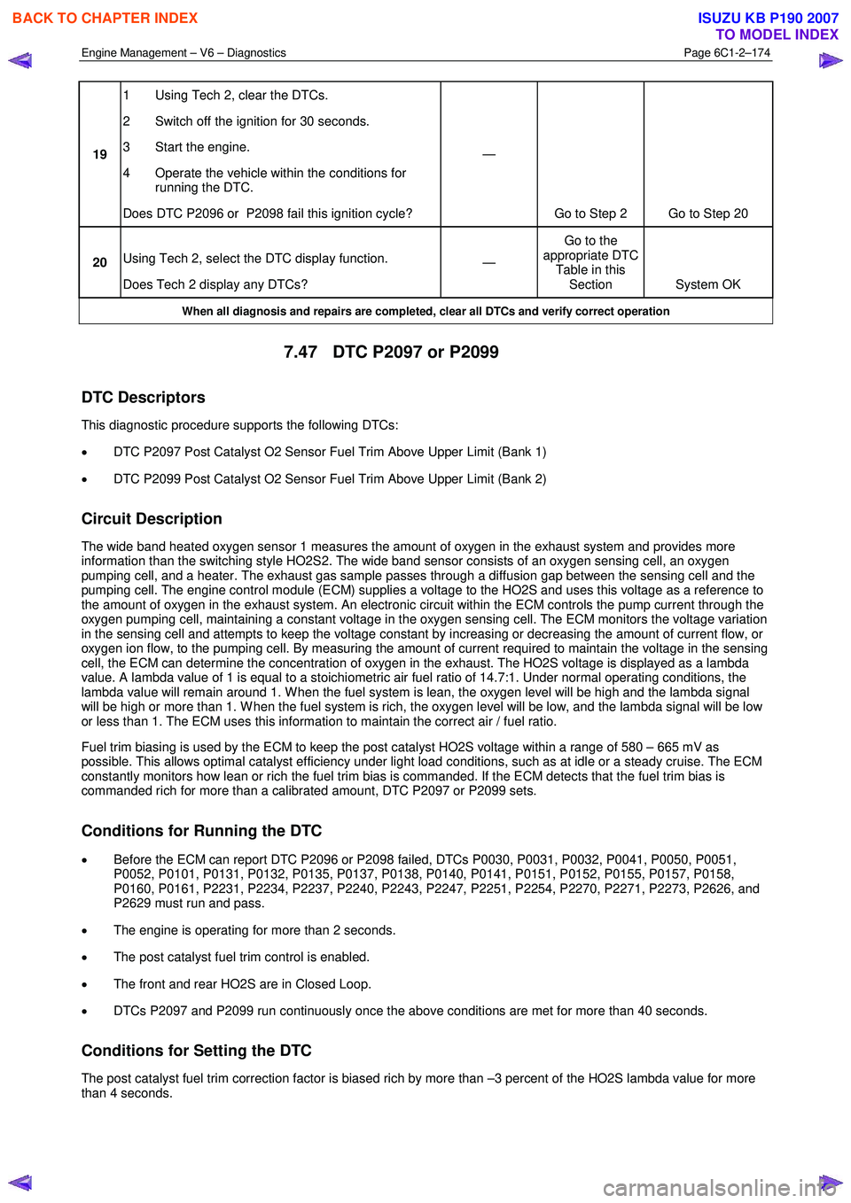
19 1 Using Tech 2, clear the DTCs.
2 Switch off the ignition for 30 seconds.
3 Start the engine.
4 Operate the vehicle within the conditions for running the DTC.
Does DTC P2096 or P2098 fail this ignition cycle? —
Go to Step 2 Go to Step 20
20 Using Tech 2, select the DTC display function.
Does Tech 2 display any DTCs? —
Go to the
appropriate DTC Table in this Section System OK
When all diagnosis and repairs are completed, clear all DTCs and verify correct operation
7.47 DTC P2097 or P2099
DTC Descriptors
This diagnostic procedure supports the following DTCs:
• DTC P2097 Post Catalyst O2 Sensor Fuel Trim Above Upper Limit (Bank 1)
• DTC P2099 Post Catalyst O2 Sensor Fuel Trim Above Upper Limit (Bank 2)
Circuit Description
The wide band heated oxygen sensor 1 measures the amount of oxygen in the exhaust system and provides more
information than the switching style HO2S2. The wide band sensor consists of an oxygen sensing cell, an oxygen
pumping cell, and a heater. The exhaust gas sample passes through a diffusion gap between the sensing cell and the
pumping cell. The engine control module (ECM) supplies a voltage to the HO2S and uses this voltage as a reference to
the amount of oxygen in the exhaust system. An electronic circuit within the ECM controls the pump current through the
oxygen pumping cell, maintaining a constant voltage in the oxygen sensing cell. The ECM monitors the voltage variation
in the sensing cell and attempts to keep the voltage constant by increasing or decreasing the amount of current flow, or
oxygen ion flow, to the pumping cell. By measuring the amount of current required to maintain the voltage in the sensing
cell, the ECM can determine the concentration of oxygen in the exhaust. The HO2S voltage is displayed as a lambda
value. A lambda value of 1 is equal to a stoichiometric air fuel ratio of 14.7:1. Under normal operating conditions, the
lambda value will remain around 1. W hen the fuel system is lean, the oxygen level will be high and the lambda signal
will be high or more than 1. W hen the fuel system is rich, the oxygen level will be low, and the lambda signal will be low
or less than 1. The ECM uses this information to maintain the correct air / fuel ratio.
Fuel trim biasing is used by the ECM to keep the post catalyst HO2S voltage within a range of 580 – 665 mV as
possible. This allows optimal catalyst efficiency under light load conditions, such as at idle or a steady cruise. The ECM
constantly monitors how lean or rich the fuel trim bias is commanded. If the ECM detects that the fuel trim bias is
commanded rich for more than a calibrated amount, DTC P2097 or P2099 sets.
Conditions for Running the DTC
• Before the ECM can report DTC P2096 or P2098 failed, DTCs P0030, P0031, P0032, P0041, P0050, P0051,
P0052, P0101, P0131, P0132, P0135, P0137, P0138, P0140, P0141, P0151, P0152, P0155, P0157, P0158,
P0160, P0161, P2231, P2234, P2237, P2240, P2243, P2247, P2251, P2254, P2270, P2271, P2273, P2626, and
P2629 must run and pass.
• The engine is operating for more than 2 seconds.
• The post catalyst fuel trim control is enabled.
• The front and rear HO2S are in Closed Loop.
• DTCs P2097 and P2099 run continuously once the above conditions are met for more than 40 seconds.
Conditions for Setting the DTC
The post catalyst fuel trim correction factor is biased rich by more than –3 percent of the HO2S lambda value for more
than 4 seconds.
BACK TO CHAPTER INDEX
TO MODEL INDEX
ISUZU KB P190 2007
Page 3462 of 6020
Engine Management – V6 – Diagnostics Page 6C1-2–184
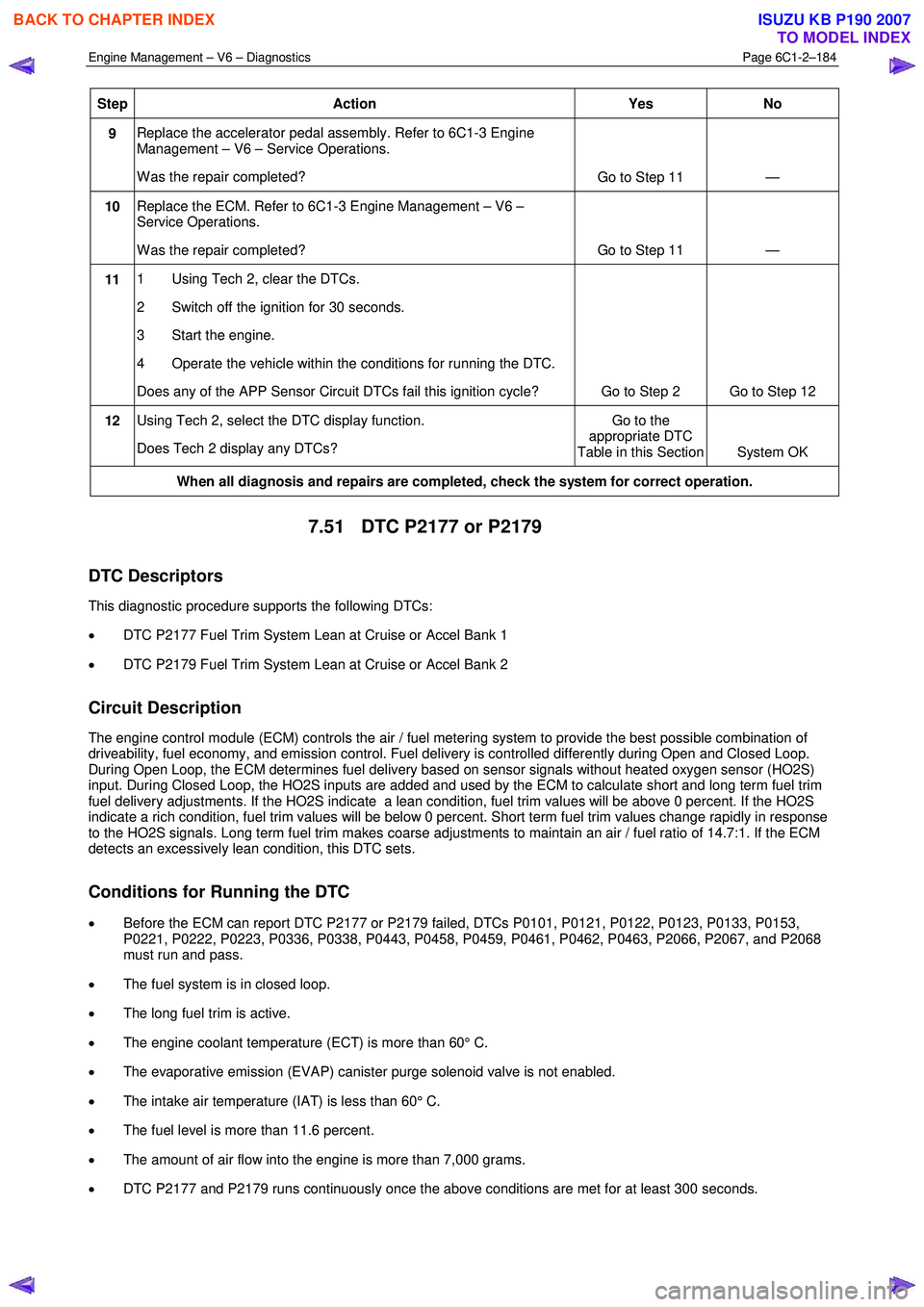
Step Action Yes No
9 Replace the accelerator pedal assembly. Refer to 6C1-3 Engine
Management – V6 – Service Operations.
W as the repair completed? Go to Step 11 —
10 Replace the ECM. Refer to 6C1-3 Engine Management – V6 –
Service Operations.
W as the repair completed? Go to Step 11 —
11 1 Using Tech 2, clear the DTCs.
2 Switch off the ignition for 30 seconds.
3 Start the engine.
4 Operate the vehicle within the conditions for running the DTC.
Does any of the APP Sensor Circuit DTCs fail this ignition cycle? Go to Step 2 Go to Step 12
12 Using Tech 2, select the DTC display function.
Does Tech 2 display any DTCs? Go to the
appropriate DTC
Table in this Section System OK
When all diagnosis and repairs are completed, check the system for correct operation.
7.51 DTC P2177 or P2179
DTC Descriptors
This diagnostic procedure supports the following DTCs:
• DTC P2177 Fuel Trim System Lean at Cruise or Accel Bank 1
• DTC P2179 Fuel Trim System Lean at Cruise or Accel Bank 2
Circuit Description
The engine control module (ECM) controls the air / fuel metering system to provide the best possible combination of
driveability, fuel economy, and emission control. Fuel delivery is controlled differently during Open and Closed Loop.
During Open Loop, the ECM determines fuel delivery based on sensor signals without heated oxygen sensor (HO2S)
input. During Closed Loop, the HO2S inputs are added and used by the ECM to calculate short and long term fuel trim
fuel delivery adjustments. If the HO2S indicate a lean condition, fuel trim values will be above 0 percent. If the HO2S
indicate a rich condition, fuel trim values will be below 0 percent. Short term fuel trim values change rapidly in response
to the HO2S signals. Long term fuel trim makes coarse adjustments to maintain an air / fuel ratio of 14.7:1. If the ECM
detects an excessively lean condition, this DTC sets.
Conditions for Running the DTC
• Before the ECM can report DTC P2177 or P2179 failed, DTCs P0101, P0121, P0122, P0123, P0133, P0153,
P0221, P0222, P0223, P0336, P0338, P0443, P0458, P0459, P0461, P0462, P0463, P2066, P2067, and P2068
must run and pass.
• The fuel system is in closed loop.
• The long fuel trim is active.
• The engine coolant temperature (ECT) is more than 60° C.
• The evaporative emission (EVAP) canister purge solenoid valve is not enabled.
• The intake air temperature (IAT) is less than 60° C.
• The fuel level is more than 11.6 percent.
• The amount of air flow into the engine is more than 7,000 grams.
• DTC P2177 and P2179 runs continuously once the above conditions are met for at least 300 seconds.
BACK TO CHAPTER INDEX
TO MODEL INDEX
ISUZU KB P190 2007
Page 3466 of 6020
Engine Management – V6 – Diagnostics Page 6C1-2–188
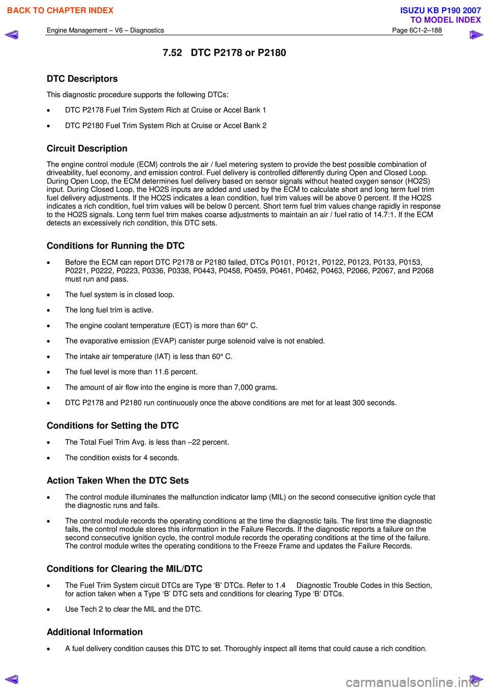
7.52 DTC P2178 or P2180
DTC Descriptors
This diagnostic procedure supports the following DTCs:
• DTC P2178 Fuel Trim System Rich at Cruise or Accel Bank 1
• DTC P2180 Fuel Trim System Rich at Cruise or Accel Bank 2
Circuit Description
The engine control module (ECM) controls the air / fuel metering system to provide the best possible combination of
driveability, fuel economy, and emission control. Fuel delivery is controlled differently during Open and Closed Loop.
During Open Loop, the ECM determines fuel delivery based on sensor signals without heated oxygen sensor (HO2S)
input. During Closed Loop, the HO2S inputs are added and used by the ECM to calculate short and long term fuel trim
fuel delivery adjustments. If the HO2S indicates a lean condition, fuel trim values will be above 0 percent. If the HO2S
indicates a rich condition, fuel trim values will be below 0 percent. Short term fuel trim values change rapidly in response
to the HO2S signals. Long term fuel trim makes coarse adjustments to maintain an air / fuel ratio of 14.7:1. If the ECM
detects an excessively rich condition, this DTC sets.
Conditions for Running the DTC
• Before the ECM can report DTC P2178 or P2180 failed, DTCs P0101, P0121, P0122, P0123, P0133, P0153,
P0221, P0222, P0223, P0336, P0338, P0443, P0458, P0459, P0461, P0462, P0463, P2066, P2067, and P2068
must run and pass.
• The fuel system is in closed loop.
• The long fuel trim is active.
• The engine coolant temperature (ECT) is more than 60° C.
• The evaporative emission (EVAP) canister purge solenoid valve is not enabled.
• The intake air temperature (IAT) is less than 60° C.
• The fuel level is more than 11.6 percent.
• The amount of air flow into the engine is more than 7,000 grams.
• DTC P2178 and P2180 run continuously once the above conditions are met for at least 300 seconds.
Conditions for Setting the DTC
• The Total Fuel Trim Avg. is less than –22 percent.
• The condition exists for 4 seconds.
Action Taken When the DTC Sets
• The control module illuminates the malfunction indicator lamp (MIL) on the second consecutive ignition cycle that
the diagnostic runs and fails.
• The control module records the operating conditions at the time the diagnostic fails. The first time the diagnostic
fails, the control module stores this information in the Failure Records. If the diagnostic reports a failure on the
second consecutive ignition cycle, the control module records the operating conditions at the time of the failure.
The control module writes the operating conditions to the Freeze Frame and updates the Failure Records.
Conditions for Clearing the MIL/DTC
• The Fuel Trim System circuit DTCs are Type ‘B’ DTCs. Refer to 1.4 Diagnostic Trouble Codes in this Section,
for action taken when a Type ‘B’ DTC sets and conditions for clearing Type ‘B’ DTCs.
• Use Tech 2 to clear the MIL and the DTC.
Additional Information
• A fuel delivery condition causes this DTC to set. Thoroughly inspect all items that could cause a rich condition.
BACK TO CHAPTER INDEX
TO MODEL INDEX
ISUZU KB P190 2007
Page 3469 of 6020
Engine Management – V6 – Diagnostics Page 6C1-2–191
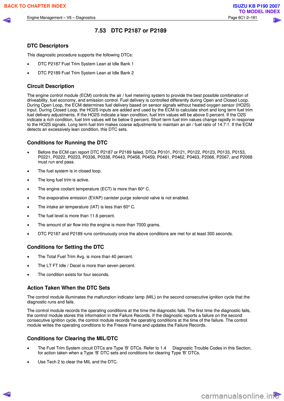
7.53 DTC P2187 or P2189
DTC Descriptors
This diagnostic procedure supports the following DTCs:
• DTC P2187 Fuel Trim System Lean at Idle Bank 1
• DTC P2189 Fuel Trim System Lean at Idle Bank 2
Circuit Description
The engine control module (ECM) controls the air / fuel metering system to provide the best possible combination of
driveability, fuel economy, and emission control. Fuel delivery is controlled differently during Open and Closed Loop.
During Open Loop, the ECM determines fuel delivery based on sensor signals without heated oxygen sensor (HO2S)
input. During Closed Loop, the HO2S inputs are added and used by the ECM to calculate short and long term fuel trim
fuel delivery adjustments. If the HO2S indicate a lean condition, fuel trim values will be above 0 percent. If the O2S
indicate a rich condition, fuel trim values will be below 0 percent. Short term fuel trim values change rapidly in response
to the HO2S signals. Long term fuel trim makes coarse adjustments to maintain an air / fuel ratio of 14.7:1. If the ECM
detects an excessively lean condition, this DTC sets.
Conditions for Running the DTC
• Before the ECM can report DTC P2187 or P2189 failed, DTCs P0101, P0121, P0122, P0123, P0133, P0153,
P0221, P0222, P0223, P0336, P0338, P0443, P0458, P0459, P0461, P0462, P0463, P2066, P2067, and P2068
must run and pass.
• The fuel system is in closed loop.
• The long fuel trim is active.
• The engine coolant temperature (ECT) is more than 60° C.
• The evaporative emission (EVAP) canister purge solenoid valve is not enabled.
• The intake air temperature (IAT) is less than 60° C.
• The fuel level is more than 11.6 percent.
• The amount of air flow into the engine is more than 7000 grams.
• DTC P2187 and P2189 runs continuously once the above conditions are met for at least 300 seconds.
Conditions for Setting the DTC
• The Total Fuel Trim Avg. is more than 40 percent.
• The LT FT Idle / Decel is more than seven percent.
• The condition exists for four seconds.
Action Taken When the DTC Sets
The control module illuminates the malfunction indicator lamp (MIL) on the second consecutive ignition cycle that the
diagnostic runs and fails.
The control module records the operating conditions at the time the diagnostic fails. The first time the diagnostic fails,
the control module stores this information in the Failure Records. If the diagnostic reports a failure on the second
consecutive ignition cycle, the control module records the operating conditions at the time of the failure. The control
module writes the operating conditions to the Freeze Frame and updates the Failure Records.
Conditions for Clearing the MIL/DTC
• The Fuel Trim System circuit DTCs are Type ‘B’ DTCs. Refer to 1.4 Diagnostic Trouble Codes in this Section,
for action taken when a Type ‘B’ DTC sets and conditions for clearing Type ‘B’ DTCs.
• Use Tech 2 to clear the MIL and the DTC.
BACK TO CHAPTER INDEX
TO MODEL INDEX
ISUZU KB P190 2007
Page 3472 of 6020
Engine Management – V6 – Diagnostics Page 6C1-2–194
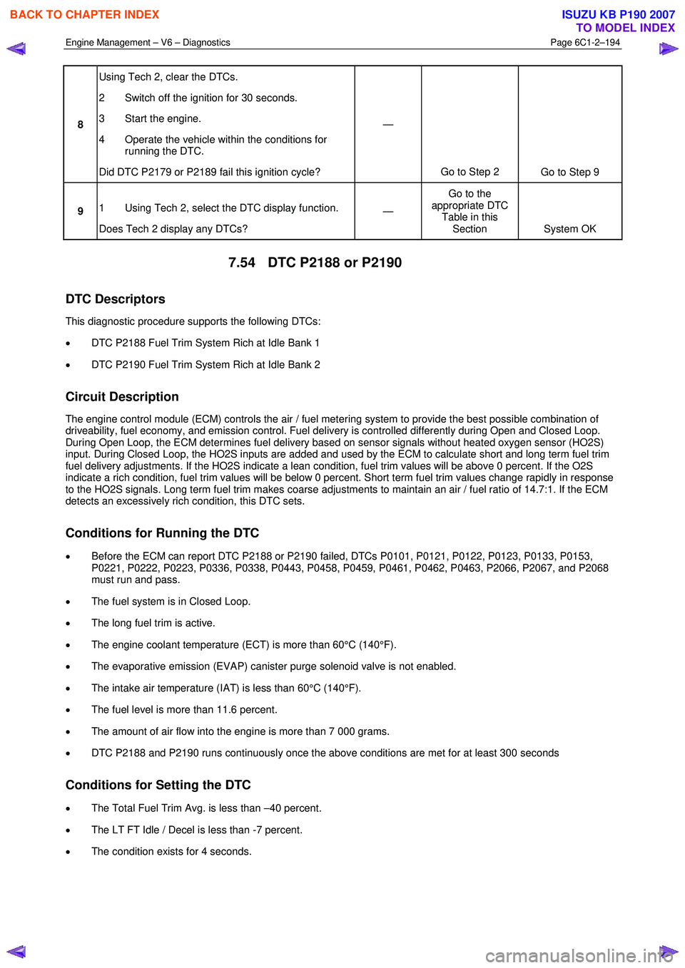
8 Using Tech 2, clear the DTCs.
2 Switch off the ignition for 30 seconds.
3 Start the engine.
4 Operate the vehicle within the conditions for running the DTC.
Did DTC P2179 or P2189 fail this ignition cycle? —
Go to Step 2 Go to Step 9
9 1 Using Tech 2, select the DTC display function.
Does Tech 2 display any DTCs? —
Go to the
appropriate DTC Table in this Section System OK
7.54 DTC P2188 or P2190
DTC Descriptors
This diagnostic procedure supports the following DTCs:
• DTC P2188 Fuel Trim System Rich at Idle Bank 1
• DTC P2190 Fuel Trim System Rich at Idle Bank 2
Circuit Description
The engine control module (ECM) controls the air / fuel metering system to provide the best possible combination of
driveability, fuel economy, and emission control. Fuel delivery is controlled differently during Open and Closed Loop.
During Open Loop, the ECM determines fuel delivery based on sensor signals without heated oxygen sensor (HO2S)
input. During Closed Loop, the HO2S inputs are added and used by the ECM to calculate short and long term fuel trim
fuel delivery adjustments. If the HO2S indicate a lean condition, fuel trim values will be above 0 percent. If the O2S
indicate a rich condition, fuel trim values will be below 0 percent. Short term fuel trim values change rapidly in response
to the HO2S signals. Long term fuel trim makes coarse adjustments to maintain an air / fuel ratio of 14.7:1. If the ECM
detects an excessively rich condition, this DTC sets.
Conditions for Running the DTC
• Before the ECM can report DTC P2188 or P2190 failed, DTCs P0101, P0121, P0122, P0123, P0133, P0153,
P0221, P0222, P0223, P0336, P0338, P0443, P0458, P0459, P0461, P0462, P0463, P2066, P2067, and P2068
must run and pass.
• The fuel system is in Closed Loop.
• The long fuel trim is active.
• The engine coolant temperature (ECT) is more than 60°C (140°F).
• The evaporative emission (EVAP) canister purge solenoid valve is not enabled.
• The intake air temperature (IAT) is less than 60°C (140°F).
• The fuel level is more than 11.6 percent.
• The amount of air flow into the engine is more than 7 000 grams.
• DTC P2188 and P2190 runs continuously once the above conditions are met for at least 300 seconds
Conditions for Setting the DTC
• The Total Fuel Trim Avg. is less than –40 percent.
• The LT FT Idle / Decel is less than -7 percent.
• The condition exists for 4 seconds.
BACK TO CHAPTER INDEX
TO MODEL INDEX
ISUZU KB P190 2007
Page 3475 of 6020
Engine Management – V6 – Diagnostics Page 6C1-2–197
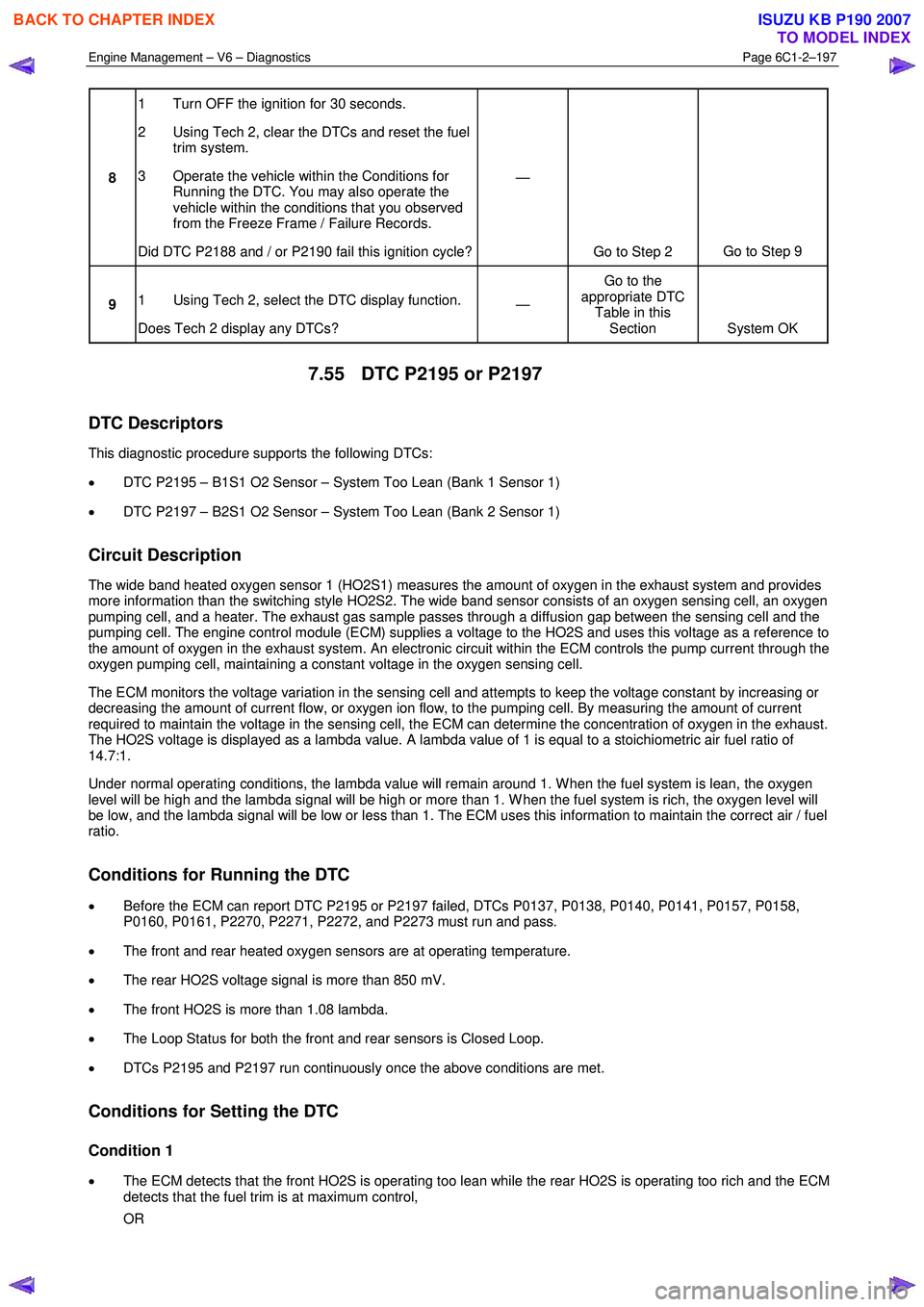
8 1 Turn OFF the ignition for 30 seconds.
2 Using Tech 2, clear the DTCs and reset the fuel trim system.
3 Operate the vehicle within the Conditions for Running the DTC. You may also operate the
vehicle within the conditions that you observed
from the Freeze Frame / Failure Records.
Did DTC P2188 and / or P2190 fail this ignition cycle? —
Go to Step 2 Go to Step 9
9 1 Using Tech 2, select the DTC display function.
Does Tech 2 display any DTCs? —
Go to the
appropriate DTC Table in this Section System OK
7.55 DTC P2195 or P2197
DTC Descriptors
This diagnostic procedure supports the following DTCs:
• DTC P2195 – B1S1 O2 Sensor – System Too Lean (Bank 1 Sensor 1)
• DTC P2197 – B2S1 O2 Sensor – System Too Lean (Bank 2 Sensor 1)
Circuit Description
The wide band heated oxygen sensor 1 (HO2S1) measures the amount of oxygen in the exhaust system and provides
more information than the switching style HO2S2. The wide band sensor consists of an oxygen sensing cell, an oxygen
pumping cell, and a heater. The exhaust gas sample passes through a diffusion gap between the sensing cell and the
pumping cell. The engine control module (ECM) supplies a voltage to the HO2S and uses this voltage as a reference to
the amount of oxygen in the exhaust system. An electronic circuit within the ECM controls the pump current through the
oxygen pumping cell, maintaining a constant voltage in the oxygen sensing cell.
The ECM monitors the voltage variation in the sensing cell and attempts to keep the voltage constant by increasing or
decreasing the amount of current flow, or oxygen ion flow, to the pumping cell. By measuring the amount of current
required to maintain the voltage in the sensing cell, the ECM can determine the concentration of oxygen in the exhaust.
The HO2S voltage is displayed as a lambda value. A lambda value of 1 is equal to a stoichiometric air fuel ratio of
14.7:1.
Under normal operating conditions, the lambda value will remain around 1. W hen the fuel system is lean, the oxygen
level will be high and the lambda signal will be high or more than 1. W hen the fuel system is rich, the oxygen level will
be low, and the lambda signal will be low or less than 1. The ECM uses this information to maintain the correct air / fuel
ratio.
Conditions for Running the DTC
• Before the ECM can report DTC P2195 or P2197 failed, DTCs P0137, P0138, P0140, P0141, P0157, P0158,
P0160, P0161, P2270, P2271, P2272, and P2273 must run and pass.
• The front and rear heated oxygen sensors are at operating temperature.
• The rear HO2S voltage signal is more than 850 mV.
• The front HO2S is more than 1.08 lambda.
• The Loop Status for both the front and rear sensors is Closed Loop.
• DTCs P2195 and P2197 run continuously once the above conditions are met.
Conditions for Setting the DTC
Condition 1
• The ECM detects that the front HO2S is operating too lean while the rear HO2S is operating too rich and the ECM
detects that the fuel trim is at maximum control,
OR
BACK TO CHAPTER INDEX
TO MODEL INDEX
ISUZU KB P190 2007