2007 ISUZU KB P190 engine mount
[x] Cancel search: engine mountPage 3603 of 6020
Charging System – V6 Page 6D1-1-16
Reinstall
Reinstallation of the generator is the reverse of the removal procedure, noting the following:
1 Tighten all fasteners to the correct torque specification.
2 Reconnect the battery ground lead.
3 Start the engine.
4 Check the generator warning indicator operation.
5 Check the drive belt is correctly routed and aligned.
6 Check the generator output. Refer to 3.3 On-vehicle Testing.
7 Check the voltage regulator operation. Refer to 3.3 On-vehicle Testing.
8 Turn the ignition switch off.
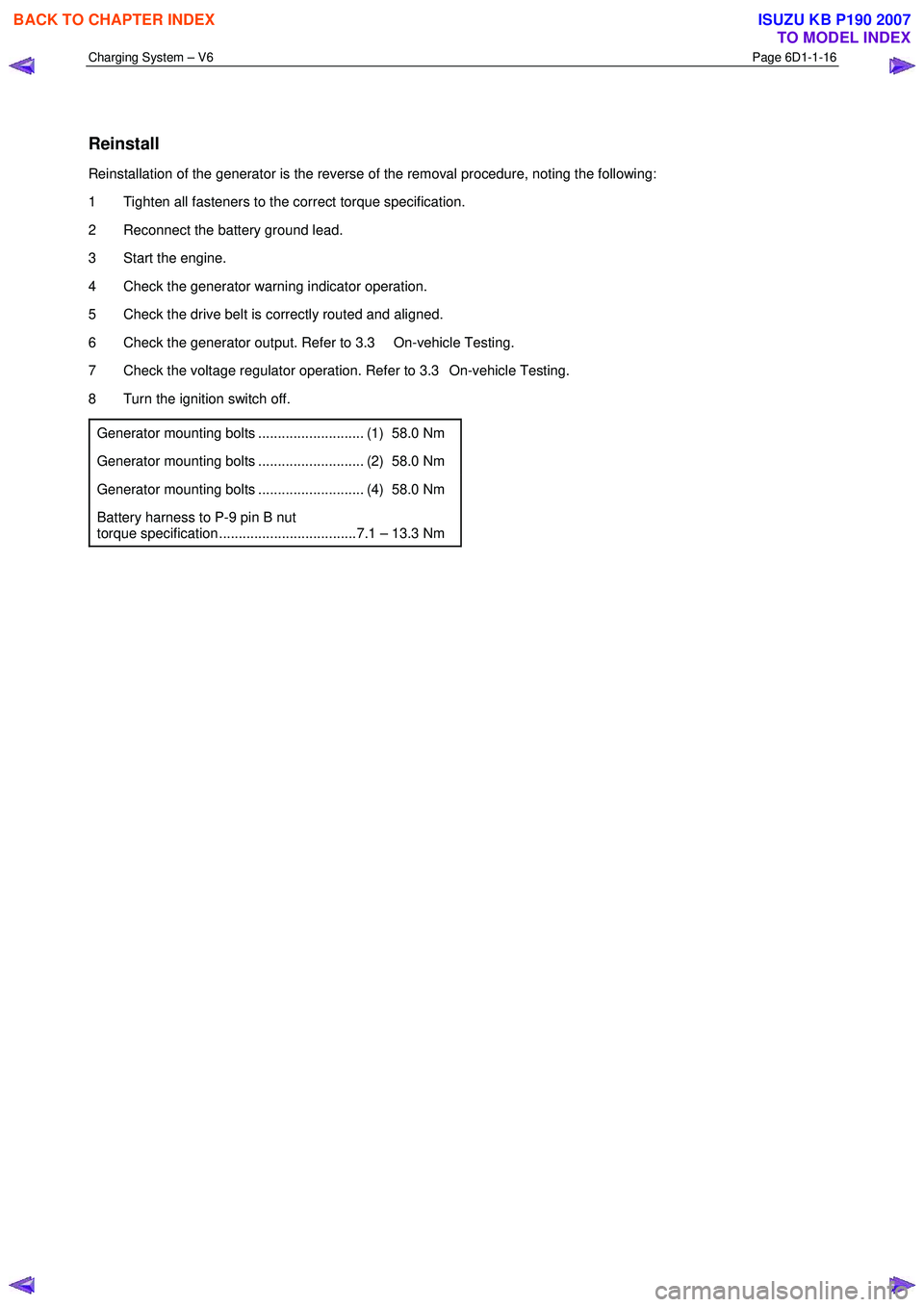
Generator mounting bolts ........................... (1) 58.0 Nm
Generator mounting bolts ........................... (2) 58.0 Nm
Generator mounting bolts ........................... (4) 58.0 Nm
Battery harness to P-9 pin B nut
torque specification ...................................7.1 – 13.3 Nm
BACK TO CHAPTER INDEX
TO MODEL INDEX
ISUZU KB P190 2007
Page 3604 of 6020
Charging System – V6 Page 6D1-1-17
4.2 Generator Mounting Bracket
Remove
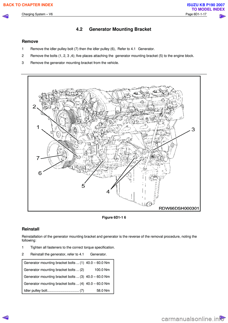
1 Remove the idler pulley bolt (7) then the idler pulley (6), Refer to 4.1 Generator.
2 Remove the bolts (1, 2, 3 ,4); five places attaching the generator mounting bracket (5) to the engine block.
3 Remove the generator mounting bracket from the vehicle.
Figure 6D1-1 6
Reinstall
Reinstallation of the generator mounting bracket and generator is the reverse of the removal procedure, noting the
following:
1 Tighten all fasteners to the correct torque specification.
2 Reinstall the generator, refer to 4.1 Generator.
Generator mounting bracket bolts ... (1) 40.0 – 60.0 Nm
Generator mounting bracket bolts ... (2) 100.0 Nm
Generator mounting bracket bolts ... (3) 40.0 – 60.0 Nm
Generator mounting bracket bolts ... (4) 40.0 – 60.0 Nm
Idler pulley bolt................................. (7) 58.0 Nm
BACK TO CHAPTER INDEX
TO MODEL INDEX
ISUZU KB P190 2007
Page 3628 of 6020
Starting System – V6 Page 6D1-2–20
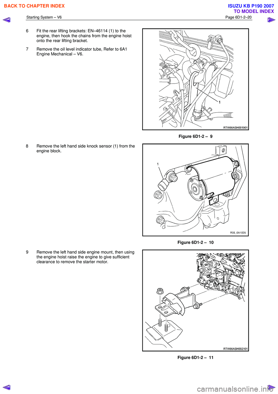
6 Fit the rear lifting brackets: EN–46114 (1) to the
engine, then hook the chains from the engine hoist
onto the rear lifting bracket.
7 Remove the oil level indicator tube, Refer to 6A1 Engine Mechanical – V6.
Figure 6D1-2 – 9
8 Remove the left hand side knock sensor (1) from the engine block.
Figure 6D1-2 – 10
9 Remove the left hand side engine mount, then using the engine hoist raise the engine to give sufficient
clearance to remove the starter motor.
Figure 6D1-2 – 11
BACK TO CHAPTER INDEX
TO MODEL INDEX
ISUZU KB P190 2007
Page 3629 of 6020
Starting System – V6 Page 6D1-2–21
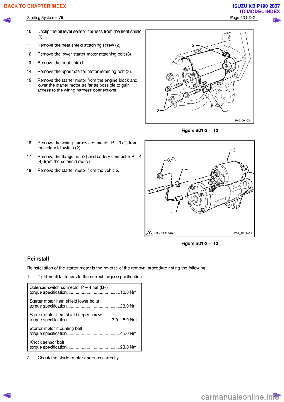
10 Unclip the oil level sensor harness from the heat shield
(1).
11 Remove the heat shield attaching screw (2).
12 Remove the lower starter motor attaching bolt (3).
13 Remove the heat shield.
14 Remove the upper starter motor retaining bolt (3).
15 Remove the starter motor from the engine block and lower the starter motor as far as possible to gain
access to the wiring harness connections.
Figure 6D1-2 – 12
16 Remove the wiring harness connector P – 3 (1) from the solenoid switch (2).
17 Remove the flange nut (3) and battery connector P – 4 (4) from the solenoid switch.
18 Remove the starter motor from the vehicle.
Figure 6D1-2 – 13
Reinstall
Reinstallation of the starter motor is the reverse of the removal procedure noting the following:
1 Tighten all fasteners to the correct torque specification.
Solenoid switch connector P – 4 nut (B+)
torque specification ............................................10.0 Nm
Starter motor heat shield lower bolts
torque specification ............................................23.0 Nm
Starter motor heat shield upper screw
torque specification .....................................3.0 – 5.0 Nm
Starter motor mounting bolt
torque specification ............................................45.0 Nm
Knock sensor bolt
torque specification ............................................23.0 Nm
2 Check the starter motor operates correctly.
BACK TO CHAPTER INDEX
TO MODEL INDEX
ISUZU KB P190 2007
Page 3674 of 6020
Powertrain Interface Module – V6 Page 6E1–13
3.2 Powertrain Interface Module Gateway
Components
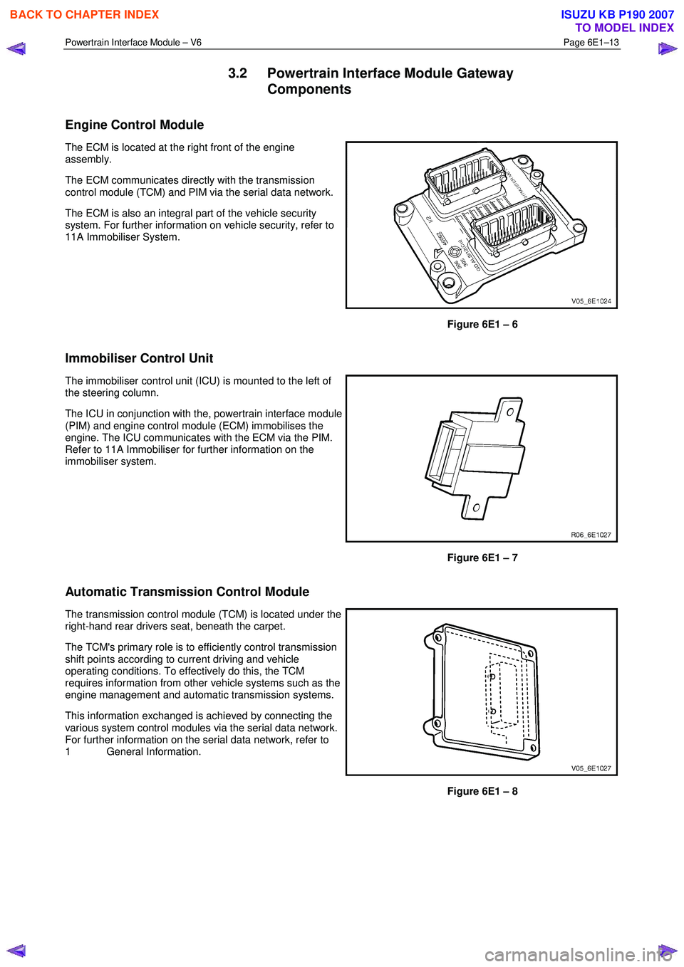
Engine Control Module
The ECM is located at the right front of the engine
assembly.
The ECM communicates directly with the transmission
control module (TCM) and PIM via the serial data network.
The ECM is also an integral part of the vehicle security
system. For further information on vehicle security, refer to
11A Immobiliser System.
Figure 6E1 – 6
Immobiliser Control Unit
The immobiliser control unit (ICU) is mounted to the left of
the steering column.
The ICU in conjunction with the, powertrain interface module
(PIM) and engine control module (ECM) immobilises the
engine. The ICU communicates with the ECM via the PIM.
Refer to 11A Immobiliser for further information on the
immobiliser system.
Figure 6E1 – 7
Automatic Transmission Control Module
The transmission control module (TCM) is located under the
right-hand rear drivers seat, beneath the carpet.
The TCM's primary role is to efficiently control transmission
shift points according to current driving and vehicle
operating conditions. To effectively do this, the TCM
requires information from other vehicle systems such as the
engine management and automatic transmission systems.
This information exchanged is achieved by connecting the
various system control modules via the serial data network.
For further information on the serial data network, refer to
1 General Information.
Figure 6E1 – 8
BACK TO CHAPTER INDEX
TO MODEL INDEX
ISUZU KB P190 2007
Page 3713 of 6020
Powertrain Interface Module – V6 Page 6E1–52
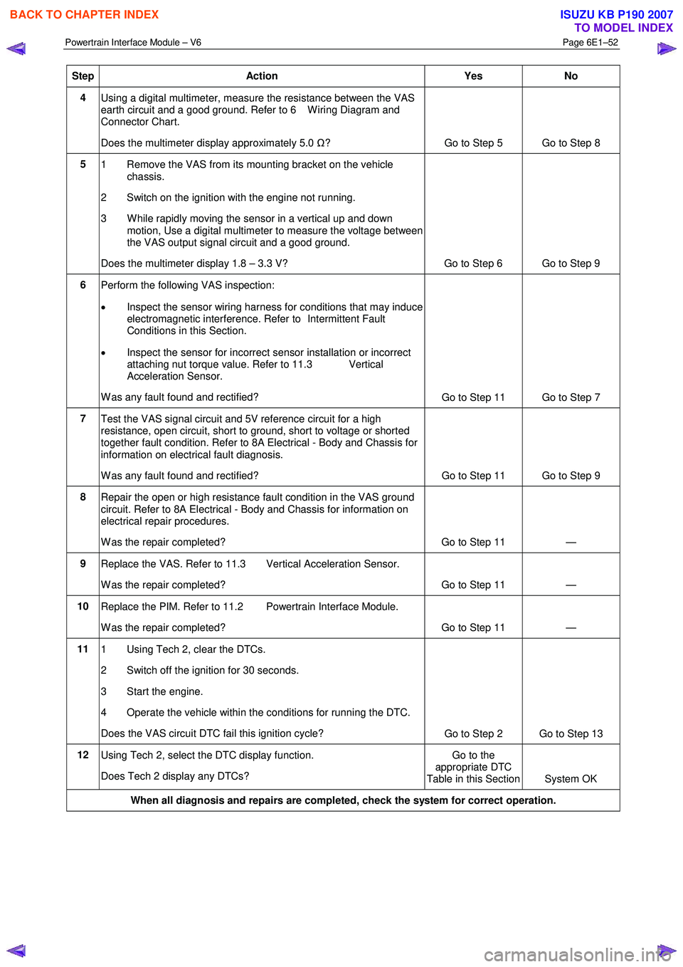
Step Action Yes No
4
Using a digital multimeter, measure the resistance between the VAS
earth circuit and a good ground. Refer to 6 W iring Diagram and
Connector Chart.
Does the multimeter display approximately 5.0 Ω?
Go to Step 5 Go to Step 8
5
1 Remove the VAS from its mounting bracket on the vehicle
chassis.
2 Switch on the ignition with the engine not running.
3 W hile rapidly moving the sensor in a vertical up and down motion, Use a digital multimeter to measure the voltage between
the VAS output signal circuit and a good ground.
Does the multimeter display 1.8 – 3.3 V? Go to Step 6 Go to Step 9
6 Perform the following VAS inspection:
• Inspect the sensor wiring harness for conditions that may induce
electromagnetic interference. Refer to Intermittent Fault
Conditions in this Section.
• Inspect the sensor for incorrect sensor installation or incorrect
attaching nut torque value. Refer to 11.3 Vertical
Acceleration Sensor.
W as any fault found and rectified? Go to Step 11 Go to Step 7
7
Test the VAS signal circuit and 5V reference circuit for a high
resistance, open circuit, short to ground, short to voltage or shorted
together fault condition. Refer to 8A Electrical - Body and Chassis for
information on electrical fault diagnosis.
W as any fault found and rectified? Go to Step 11 Go to Step 9
8
Repair the open or high resistance fault condition in the VAS ground
circuit. Refer to 8A Electrical - Body and Chassis for information on
electrical repair procedures.
W as the repair completed? Go to Step 11 —
9 Replace the VAS. Refer to 11.3 Vertical Acceleration Sensor.
W as the repair completed? Go to Step 11 —
10 Replace the PIM. Refer to 11.2 Powertrain Interface Module.
W as the repair completed? Go to Step 11 —
11 1 Using Tech 2, clear the DTCs.
2 Switch off the ignition for 30 seconds.
3 Start the engine.
4 Operate the vehicle within the conditions for running the DTC.
Does the VAS circuit DTC fail this ignition cycle? Go to Step 2 Go to Step 13
12
Using Tech 2, select the DTC display function.
Does Tech 2 display any DTCs? Go to the
appropriate DTC
Table in this Section System OK
When all diagnosis and repairs are completed, check the system for correct operation.
BACK TO CHAPTER INDEX
TO MODEL INDEX
ISUZU KB P190 2007
Page 3732 of 6020
Powertrain Interface Module – V6 Page 6E1–71
11 Service Operations
11.1 Safety and Precautionary Measures
The following safety and precautionary
measures must be followed when servicing
and diagnosing the powertrain interface
module (PIM) System. Otherwise, personal
injury and / or improper braking system
operation may occur:
• W hen using electric welding equipment, disconnect the wiring harness connector from the PIM.
• Never disconnect or reconnect the PIM wiring harness connector when the ignition is switched ON.
• Do not touch the PIM connector pins or soldered components on the PIM circuit board to prevent possible
Electrostatic Discharge damage.
• To avoid wiring connector terminal damage, always use suitable wiring harness test leads (such as those in Tool
No, J35616) when performing tests on the PIM wiring connector.
• The PIM is extremely sensitive to Electro Magnetic Interference (EMI). Ensure the PIM wiring harness is routed
correctly and securely fitted to mounting clips when performing service procedures.
• Due to the sensitive nature of the PIM circuitry, specific wiring repair procedures have been developed. These
procedures and instructions are detailed in 8A Electrical - Body and Chassis and are the only recommended and
approved wiring repair methods.
• Ensure that all wiring harness connectors are seated correctly.
• Never disconnect the battery from the vehicle electrical system while the engine is running.
• Always disconnect the battery from the vehicle electrical system before charging.
• Do not use a fast charger for starting the vehicle.
• Ensure the battery cable terminals are secure.
• Before installing a new PIM, ensure the correct type is fitted. Always refer to the latest spare parts information.
11.2 Powertrain Interface Module
Do not touch the powertrain interface module
pins as Electrostatic Discharge (ESD) damage
may result. For further information on ESD,
refer to 1.2 Warning Caution and Notes.
When replacing the PIM, the PIM must be
reset prior to removal. Failure to perform this
procedure will result in the inability to:
• Test the PIM for warranty purposes.
• Install the PIM into other vehicles.
BACK TO CHAPTER INDEX
TO MODEL INDEX
ISUZU KB P190 2007
Page 3751 of 6020
Exhaust System – V6 Page 6F – 3
The Catalytic converter can be damaged or
rendered ineffective, if:
• operated outside the limits of the closed
loop mixture control system
• the engine burns excessive amount of oil
• the exhaust temperature at the converter
is too high (exceeds 840°C).
The catalytic material is very sensitive to the effects of a rich or lean fuel mixture, which may cause the temperature of
the converter to rise rapidly. The catalytic converter normally operates at approximately 600 °C.
The catalytic converter is also sensitive to the use of leaded petrol. Using leaded fuel can cause deposits to form in the
converter, which restrict exhaust flow and prevent the catalyst from working. This will result in an increase in exhaust
backpressure and converter temperature.
NOTE
The use of unleaded petrol results in black
tailpipe deposits rather than the grey colour that
some people may normally associate with an
acceptable combustion condition. This black
colour resulting from the use of unleaded fuel
does not necessarily indicate a state of poor
engine tune. For V6 engines, Refer to: 6C1 – 1
Engine Management General Information.
Euro 3 Emissions Standards
The Euro 3 emissions standard is a European standard which aims at setting vehicle emissions targets to encourage
vehicle manufacturers to reduce harmful vehicle emissions such as Carbon Monoxide (CO), Hydrocarbons (HC) and the
various oxides of Nitrogen (NOx).
This vehicle is fitted with a supplemental
restraint system (SRS). Refer to section 9A
Restraints, in order to determine whether you
are performing service on or near the SRS
components or the SRS wiring.
Always use the correct fastener in the proper
location. When you replace a fastener, use
ONLY the exact part number for that
application. Isuzu will identify those fasteners
that require a replacement after removal and
fasteners that require thread lockers or thread
sealant. Unless otherwise specified, do not
use supplemental coatings (Paints, greases
or corrosion inhibitors) on thread fasteners or
fastener joints. Generally such coatings
adversely effect the fastener torque and the
joint clamping force, and may damage the
fastener. When you install fasteners, use the
correct tightening sequence and torque
specifications.
BACK TO CHAPTER INDEX
TO MODEL INDEX
ISUZU KB P190 2007