2007 ISUZU KB P190 engine mount
[x] Cancel search: engine mountPage 4096 of 6020
ON-VEHICLE SERVICE (AW30–40LE) 7A3-11
Measure Time Lag
1. Fully apply the parking brake.
2. Start the engine. Check idling speed (A/C OFF).
3. Operate the select lever from “N" to “D" position.
Using a stopwatch, measure the time it takes from
shifting the lever until the shock is felt.
Time lag: Less than 0.7 seconds
4. In same manner, measure the time lag for “N" →
“R".
Time lag: Less than 1.2 seconds
Evaluation
1. If “N" → “D" time lag is longer than specified:
• Line pressure too low
• Forward clutch malfunction
• No.2 one-way clutch not operating properly
2. If “N" → “R" time lag is longer than specified:
• Line pressure too low
• Direct clutch malfunction
• First and Reverse brake malfunction
3. If both time lag is longer than specified:
• Line pressure too low
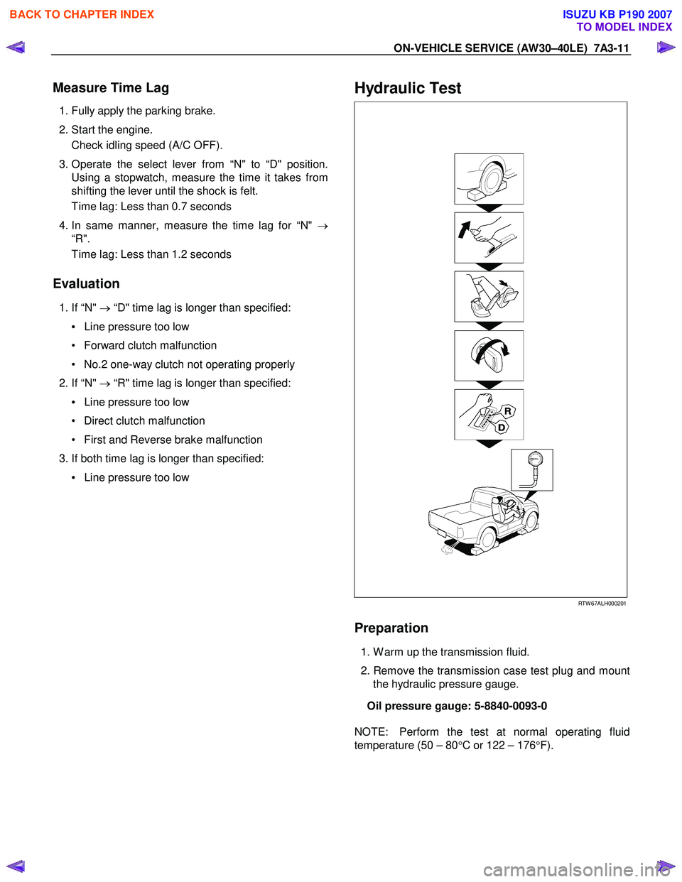
Hydraulic Test
RTW 67ALH000201
Preparation
1. W arm up the transmission fluid.
2. Remove the transmission case test plug and mount the hydraulic pressure gauge.
Oil pressure gauge: 5-8840-0093-0
NOTE: Perform the test at normal operating fluid
temperature (50 – 80 °C or 122 – 176 °F).
BACK TO CHAPTER INDEX
TO MODEL INDEX
ISUZU KB P190 2007
Page 4117 of 6020
7A3-32 ON-VEHICLE SERVICE (AW30–40LE)
Shift Solenoid and Lock-Up Solenoid
Removal
Preparation:
• Disconnect negative (–) battery cable.
• Drain the fluid.
Refer to ATF REPLACEMENT in this section.
1. Remove oil lever gage and oil filler tube.
2. Support transfer case (4
×4) or rear cover (4×2)
with a transmission jack.
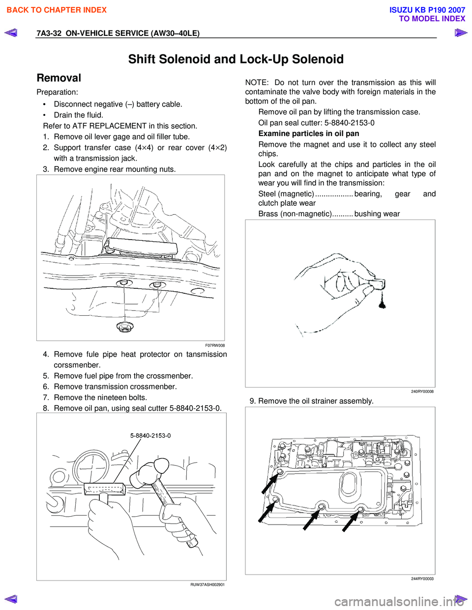
3. Remove engine rear mounting nuts.
F07RW 008
4. Remove fule pipe heat protector on tansmission
corssmenber.
5. Remove fuel pipe from the crossmenber.
6. Remove transmission crossmenber.
7. Remove the nineteen bolts.
8. Remove oil pan, using seal cutter 5-8840-2153-0.
RUW 37ASH002901
NOTE: Do not turn over the transmission as this will
contaminate the valve body with foreign materials in the
bottom of the oil pan.
Remove oil pan by lifting the transmission case.
Oil pan seal cutter: 5-8840-2153-0
Examine particles in oil pan
Remove the magnet and use it to collect any steel
chips.
Look carefully at the chips and particles in the oil
pan and on the magnet to anticipate what type o
f
wear you will find in the transmission:
Steel (magnetic) .................. bearing, gear and
clutch plate wear
Brass (non-magnetic).......... bushing wear
240RY00008
9. Remove the oil strainer assembly.
244RY00003
BACK TO CHAPTER INDEX
TO MODEL INDEX
ISUZU KB P190 2007
Page 4128 of 6020
ON-VEHICLE SERVICE (AW30–40LE) 7A3-43
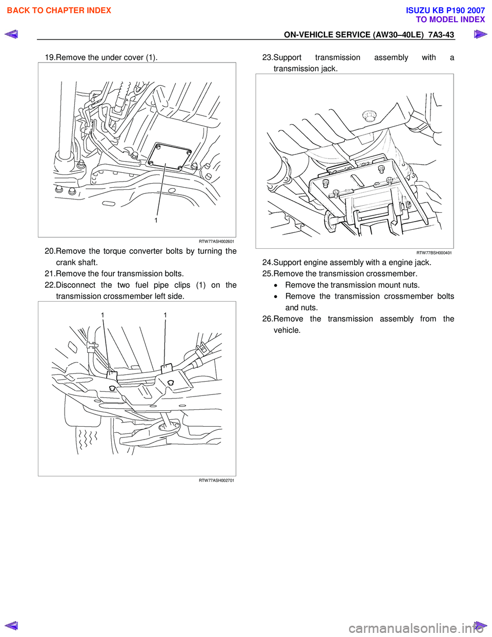
19.Remove the under cover (1).
RTW 77ASH002601
20.Remove the torque converter bolts by turning the
crank shaft.
21.Remove the four transmission bolts.
22.Disconnect the two fuel pipe clips (1) on the transmission crossmember left side.
RTW 77ASH002701
23.Support transmission assembly with a
transmission jack.
RTW 77BSH000401
24.Support engine assembly with a engine jack.
25.Remove the transmission crossmember. • Remove the transmission mount nuts.
• Remove the transmission crossmember bolts
and nuts.
26.Remove the transmission assembly from the vehicle.
BACK TO CHAPTER INDEX
TO MODEL INDEX
ISUZU KB P190 2007
Page 4129 of 6020
7A3-44 ON-VEHICLE SERVICE (AW30–40LE)
Installation
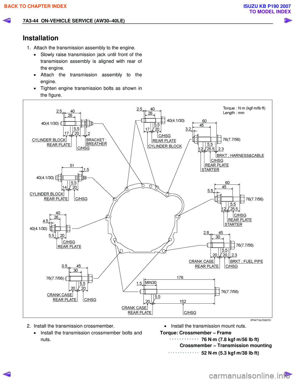
1. Attach the transmission assembly to the engine.
• Slowly raise transmission jack until front of the
transmission assembly is aligned with rear o
f
the engine.
•
Attach the transmission assembly to the
engine.
• Tighten engine transmission bolts as shown in
the figure.
RTW 77ALF000701
2. Install the transmission crossmember.
• Install the transmission crossmember bolts and
nuts.
• Install the transmission mount nuts.
Torque: Crossmember ∼
∼∼
∼
Frame
・
・・
・・
・・
・・
・・
・・
・・
・・
・・
・・
・・
・・
・・
・・
・・
・・
・・
・・
・・
・・
・・
・・
・・
・
76 N ⋅
⋅⋅
⋅
m (7.8 kgf ⋅m/56 lb ⋅ft)
Crossmember ∼
∼∼
∼
Transmission mounting
・・・・・・・・・・・・・
52 N⋅
⋅⋅
⋅
m (5.3 kgf ⋅m/38 lb ⋅ft)
BACK TO CHAPTER INDEX
TO MODEL INDEX
ISUZU KB P190 2007
Page 4354 of 6020
7A2-70 TRANSMISSION CONTROL SYSTEM (JR405E)
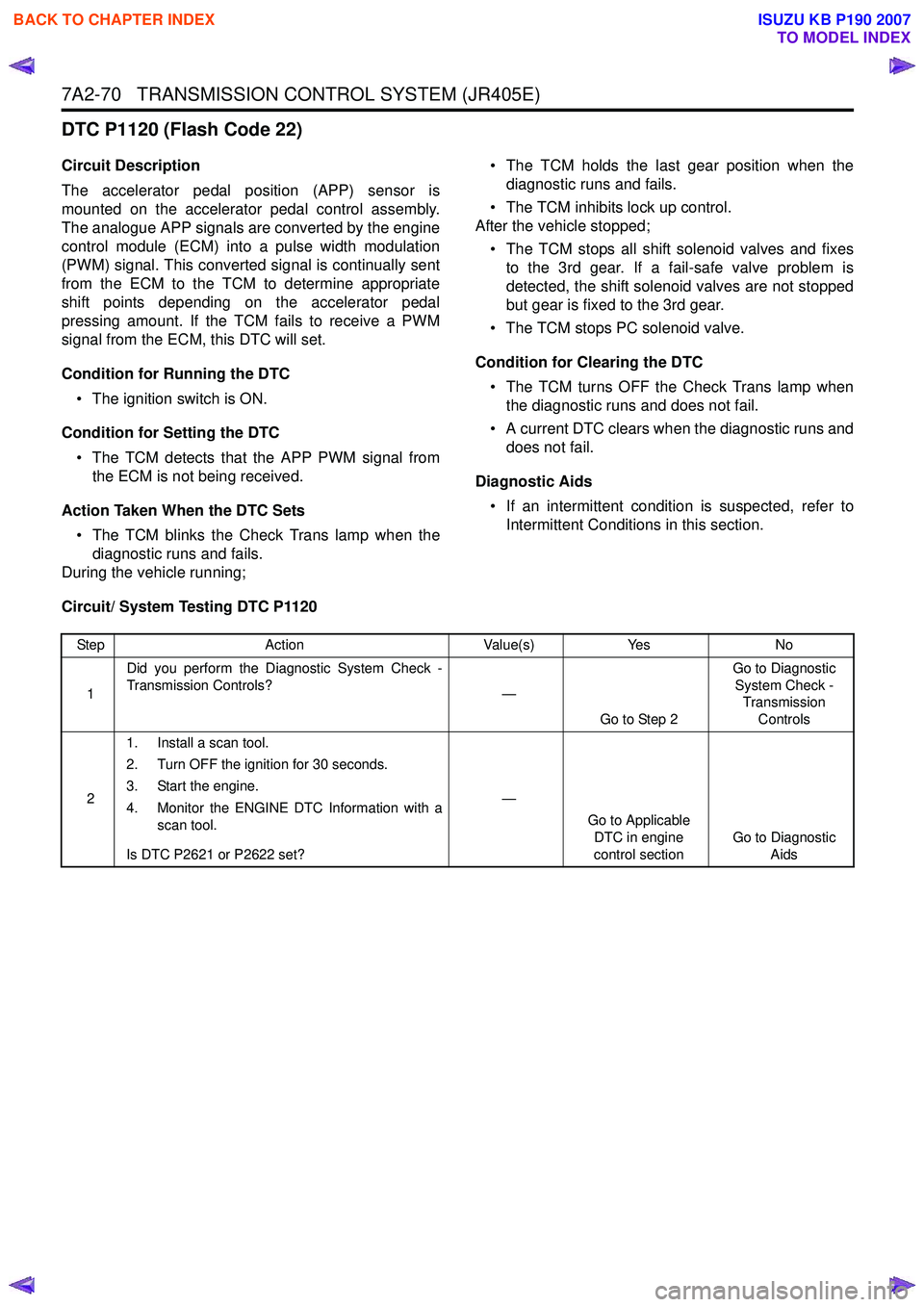
DTC P1120 (Flash Code 22)
Circuit Description
The accelerator pedal position (APP) sensor is
mounted on the accelerator pedal control assembly.
The analogue APP signals are converted by the engine
control module (ECM) into a pulse width modulation
(PWM) signal. This converted signal is continually sent
from the ECM to the TCM to determine appropriate
shift points depending on the accelerator pedal
pressing amount. If the TCM fails to receive a PWM
signal from the ECM, this DTC will set.
Condition for Running the DTC • The ignition switch is ON.
Condition for Setting the DTC • The TCM detects that the APP PWM signal from the ECM is not being received.
Action Taken When the DTC Sets • The TCM blinks the Check Trans lamp when the diagnostic runs and fails.
During the vehicle running; • The TCM holds the last gear position when the
diagnostic runs and fails.
• The TCM inhibits lock up control.
After the vehicle stopped;
• The TCM stops all shift solenoid valves and fixes to the 3rd gear. If a fail-safe valve problem is
detected, the shift solenoid valves are not stopped
but gear is fixed to the 3rd gear.
• The TCM stops PC solenoid valve.
Condition for Clearing the DTC • The TCM turns OFF the Check Trans lamp when the diagnostic runs and does not fail.
• A current DTC clears when the diagnostic runs and does not fail.
Diagnostic Aids • If an intermittent condition is suspected, refer to Intermittent Conditions in this section.
Circuit/ System Testing DTC P1120
Step Action Value(s)Yes No
1 Did you perform the Diagnostic System Check -
Transmission Controls? —
Go to Step 2 Go to Diagnostic
System Check - Transmission
Controls
2 1. Install a scan tool.
2. Turn OFF the ignition for 30 seconds.
3. Start the engine.
4. Monitor the ENGINE DTC Information with a scan tool.
Is DTC P2621 or P2622 set? —
Go to Applicable DTC in engine
control section Go to Diagnostic
Aids
BACK TO CHAPTER INDEX
TO MODEL INDEX
ISUZU KB P190 2007
Page 4389 of 6020
TRANSMISSION CONTROL SYSTEM (JR405E) 7A2-105
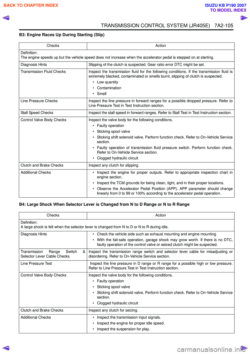
B3: Engine Races Up During Starting (Slip)
B4: Large Shock When Selector Lever is Changed from N to D Range or N to R Range
Checks Action
Definition:
The engine speeds up but the vehicle speed does not increase when the accelerator pedal is stepped on at starting.
Diagnosis Hints Slipping of the clutch is suspected. Gear ratio error DTC might be set.
Transmission Fluid Checks Inspect the transmission fluid for the following conditions. If the transmission fluid is
extremely blacked, contaminated or smells burnt, slipping of clutch is suspected.
• Low quantity
• Contamination
•Smell
Line Pressure Checks Inspect the line pressure in forward ranges for a possible dropped pressure. Refer to
Line Pressure Test in Test Instruction section.
Stall Speed Checks Inspect the stall speed in forward ranges. Refer to Stall Test in Test Instruction section.
Control Valve Body Checks Inspect the valve body for the following conditions.
• Faulty operation
• Sticking spool valve
• Sticking shift solenoid valve. Perform function check. Refer to On-Vehicle Service section.
• Faulty operation of transmission fluid pressure switch. Perform function check. Refer to On-Vehicle Service section.
• Clogged hydraulic circuit
Clutch and Brake Checks Inspect any clutch for slipping.
Additional Checks • Inspect the engine for proper outputs. Refer to appropriate inspection chart in
engine section.
• Inspect the TCM grounds for being clean, tight, and in their proper locations.
• Observe the Accelerator Pedal Position (APP). APP parameter should change linearly from 0 to 99 or 100% according to the accelerator pedal operation.
Checks Action
Definition:
A large shock is felt when the selector lever is changed from N to D or N to R during idle.
Diagnosis Hints • Check the vehicle side such as exhaust mounting and engine mounting.
• With the fail-safe operation, garage shock may grow worth. If there is no DTC, faulty operation of the control valve or seized clutch might be suspected.
Transmission Range Switch &
Selector Lever Cable Checks Inspect the transmission range switch and selector lever cable for misadjusting or
disordering. Refer to On-Vehicle Service section.
Line Pressure Test Inspect the line pressure in D range or R range for a possible high or low pressure.
Refer to Line Pressure Test in Test Instruction section.
Control Valve Body Checks Inspect the valve body for the following conditions.
• Faulty operation
• Sticking spool valve
• Sticking shift solenoid valve. Perform function check. Refer to On-Vehicle Service section.
• Clogged hydraulic circuit
Clutch and Brake Checks Inspect any clutch for seizing.
Additional Checks • Inspect the transmission input signals.
• Inspect the engine for proper idle speed.
• Inspect the suspension for play.
BACK TO CHAPTER INDEX
TO MODEL INDEX
ISUZU KB P190 2007
Page 4408 of 6020
7A2-124 TRANSMISSION CONTROL SYSTEM (JR405E)
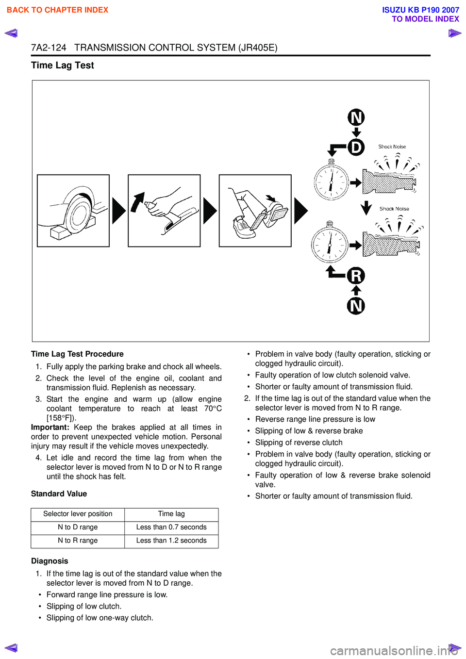
Time Lag Test
Time Lag Test Procedure1. Fully apply the parking brake and chock all wheels.
2. Check the level of the engine oil, coolant and transmission fluid. Replenish as necessary.
3. Start the engine and warm up (allow engine coolant temperature to reach at least 70 °C
[158 °F]).
Important: Keep the brakes applied at all times in
order to prevent unexpected vehicle motion. Personal
injury may result if the vehicle moves unexpectedly.
4. Let idle and record the time lag from when the selector lever is moved from N to D or N to R range
until the shock has felt.
Standard Value
Diagnosis 1. If the time lag is out of the standard value when the selector lever is moved from N to D range.
• Forward range line pressure is low.
• Slipping of low clutch.
• Slipping of low one-way clutch. • Problem in valve body (faulty operation, sticking or
clogged hydraulic circuit).
• Faulty operation of low clutch solenoid valve.
• Shorter or faulty amount of transmission fluid.
2. If the time lag is out of the standard value when the selector lever is moved from N to R range.
• Reverse range line pressure is low
• Slipping of low & reverse brake
• Slipping of reverse clutch
• Problem in valve body (faulty operation, sticking or clogged hydraulic circuit).
• Faulty operation of low & reverse brake solenoid valve.
• Shorter or faulty amount of transmission fluid.
Selector lever position Time lag
N to D range Less than 0.7 seconds
N to R range Less than 1.2 seconds
BACK TO CHAPTER INDEX
TO MODEL INDEX
ISUZU KB P190 2007
Page 4436 of 6020
7A2-152 TRANSMISSION CONTROL SYSTEM (JR405E)
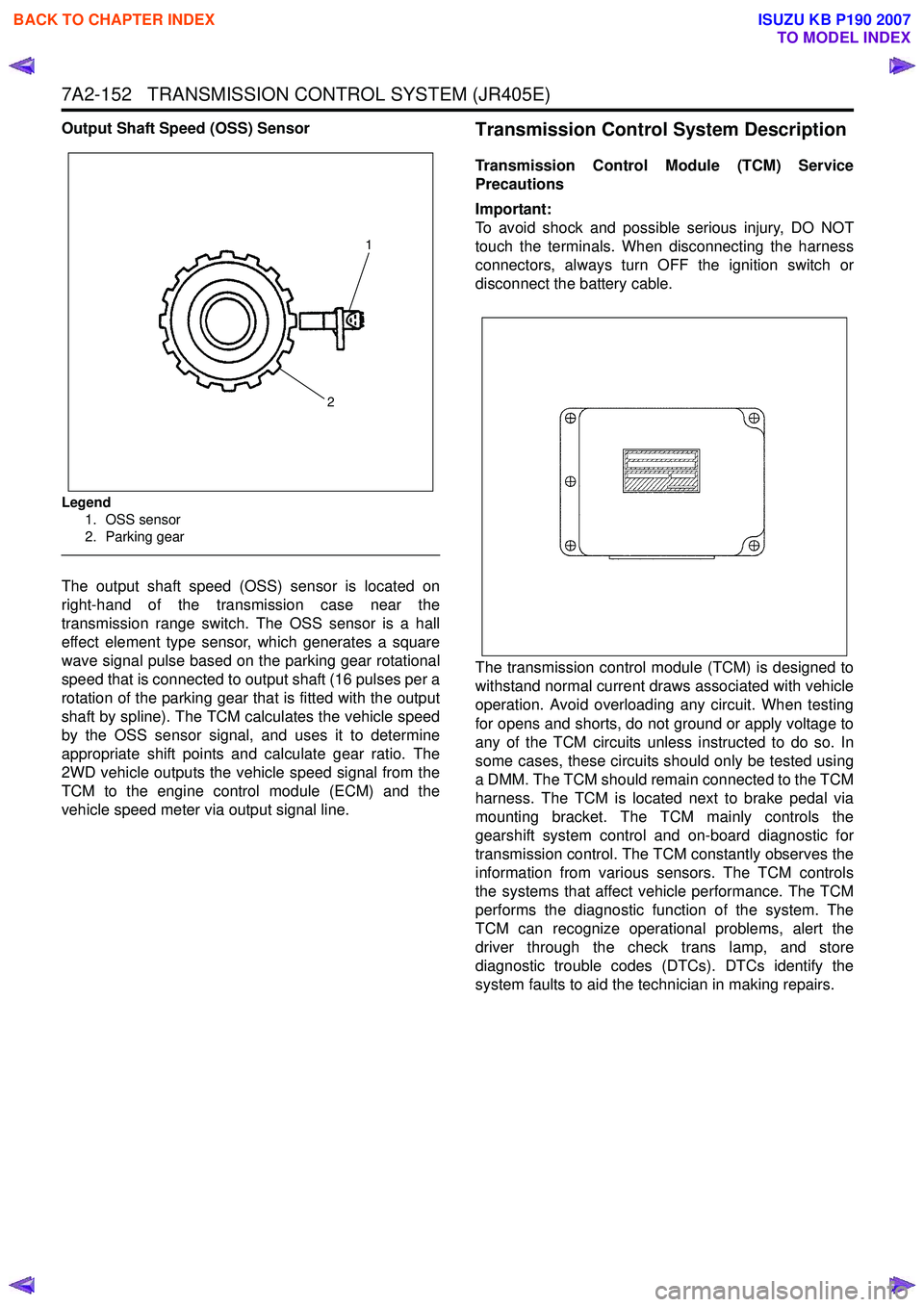
Output Shaft Speed (OSS) Sensor
Legend1. OSS sensor
2. Parking gear
The output shaft speed (OSS) sensor is located on
right-hand of the transmission case near the
transmission range switch. The OSS sensor is a hall
effect element type sensor, which generates a square
wave signal pulse based on the parking gear rotational
speed that is connected to output shaft (16 pulses per a
rotation of the parking gear that is fitted with the output
shaft by spline). The TCM calculates the vehicle speed
by the OSS sensor signal, and uses it to determine
appropriate shift points and calculate gear ratio. The
2WD vehicle outputs the vehicle speed signal from the
TCM to the engine control module (ECM) and the
vehicle speed meter via output signal line.
Transmission Control System Description
Transmission Control Module (TCM) Service
Precautions
Important:
To avoid shock and possible serious injury, DO NOT
touch the terminals. When disconnecting the harness
connectors, always turn OFF the ignition switch or
disconnect the battery cable.
The transmission control module (TCM) is designed to
withstand normal current draws associated with vehicle
operation. Avoid overloading any circuit. When testing
for opens and shorts, do not ground or apply voltage to
any of the TCM circuits unless instructed to do so. In
some cases, these circuits should only be tested using
a DMM. The TCM should remain connected to the TCM
harness. The TCM is located next to brake pedal via
mounting bracket. The TCM mainly controls the
gearshift system control and on-board diagnostic for
transmission control. The TCM constantly observes the
information from various sensors. The TCM controls
the systems that affect vehicle performance. The TCM
performs the diagnostic function of the system. The
TCM can recognize operational problems, alert the
driver through the check trans lamp, and store
diagnostic trouble codes (DTCs). DTCs identify the
system faults to aid the technician in making repairs.
1
2
BACK TO CHAPTER INDEX
TO MODEL INDEX
ISUZU KB P190 2007