Page 4667 of 6020
MANUAL TRANSMISSION 7B1-61
Transmission (4×
××
×
4)
Disassembled View
RTW 77BLF003601
Legend
(1) Gear Control Lever Knob (10) Transfer Assembly
(2) Rear Floor Console (bucket) (11) Fuel Pipe Bracket
(3) Front Floor Console (12) Slave Cylinder
(4) Grommet Assembly (13) Rear Mount Nut
(5) Gear Control Lever (14) Transmission Crossmember
(6) Rear Propeller Shaft (15) Starter (Diesel engine only)
(7) Front Propeller Shaft (16) Transmission Retaining Nut and Bolt
(8) Exhaust Pipe Nut (Diesel engine) (17) Transmission Assembly
(9) Transmission-Transfer Fixing Bolt
BACK TO CHAPTER INDEX
TO MODEL INDEX
ISUZU KB P190 2007
Page 4670 of 6020
7B1-64 MANUAL TRANSMISSION
12. Remove the fuel pipe brackets with pipes from the
transmission.
Diesel engine
220R300012
Legend
(1) Bolt
(2) Nut
(3) Fuel Pipe Assembly
C24SE
Scan-2
13. Remove the slave cylinder and put it aside.
220LV019
14. Support the transmission with a transmission jack.
220RS0001
15. Remove the engine rear mount nuts from the
transmission crossmember.
BACK TO CHAPTER INDEX
TO MODEL INDEX
ISUZU KB P190 2007
Page 4671 of 6020
MANUAL TRANSMISSION 7B1-65
16. Remove the engine rear mount bolts fixing
transmission.
220R300009
17. Remove the middle part of the transmissioncrossmember by removing the four fixing bolts and
nuts.
501R30007
18. Take out the rear support rubber. 19. Remove the starter. (Diesel engine only)
060L100070
20. Remove the transmission retaining nuts and bolts.
Remove the transmission assembly from the
vehicle.
21. Remove the transmission–transfer fixing bolts and nut, and disassemble the transfer from the
transmission.
BACK TO CHAPTER INDEX
TO MODEL INDEX
ISUZU KB P190 2007
Page 4675 of 6020

MANUAL TRANSMISSION 7B1-69
8. Install the starter. (Diesel engine)
NOTE: Tighten the lower bolt temporarily.
After installing the fuel pipe assembly, tighten the bolt to
the specified torque.
Torque: 76 N ⋅
⋅⋅
⋅
m (7.7 kgf ⋅
⋅⋅
⋅
m/56 lb ⋅
⋅⋅
⋅
ft)
9. Install the rear support rubber on the transmission and tighten the bolts to the specified torque.
Torque: 50 N ⋅
⋅⋅
⋅
m (5.1 kgf ⋅
⋅⋅
⋅
m/37 lb ⋅
⋅⋅
⋅
ft)
10. Install the middle part of transmission crossmember and bolts.
Tighten the nuts to the specified torque.
Torque: 67 N ⋅
⋅⋅
⋅
m (6.8 kgf ⋅
⋅⋅
⋅
m/49 lb ⋅
⋅⋅
⋅
ft)
11. Install the engine rear mount nuts.
Torque: 52 N ⋅
⋅⋅
⋅
m (5.3 kgf ⋅
⋅⋅
⋅
m/38 lb ⋅
⋅⋅
⋅
ft)
Remove the transmission jack from the
transmission side.
12. Apply grease to top hole portion of the shift fork. Install the slave cylinder and tighten the bolts to the
specified torque.
Torque: 76 N ⋅
⋅⋅
⋅
m (7.7 kgf ⋅
⋅⋅
⋅
m/56 lb ⋅
⋅⋅
⋅
ft)
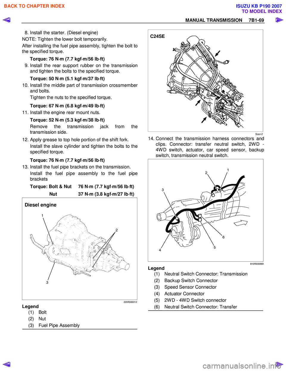
13. Install the fuel pipe brackets on the transmission.
Install the fuel pipe assembly to the fuel pipe brackets
Torque: Bolt & Nut 76 N ⋅
⋅⋅
⋅
m (7.7 kgf ⋅
⋅⋅
⋅
m/56 lb ⋅
⋅⋅
⋅
ft)
Nut 37 N ⋅
⋅⋅
⋅
m (3.8 kgf ⋅
⋅⋅
⋅
m/27 lb ⋅
⋅⋅
⋅
ft)
Diesel engine
220R300012
Legend
(1) Bolt
(2) Nut
(3) Fuel Pipe Assembly
C24SE
Scan-2
14. Connect the transmission harness connectors and
clips. Connector: transfer neutral switch, 2W D -
4W D switch, actuator, car speed sensor, backup
switch, transmission neutral switch.
810R300069
Legend
(1) Neutral Switch Connector: Transmission
(2) Backup Switch Connector
(3) Speed Sensor Connector
(4) Actuator Connector
(5) 2W D - 4W D Switch connector
(6) Neutral Switch Connector: Transfer
BACK TO CHAPTER INDEX
TO MODEL INDEX
ISUZU KB P190 2007
Page 4731 of 6020

7B1-12 Manual Transmission (MUX)
22. Remove the transmission retaining nuts and bolts.Remove the transmission assembly (4x2 model) or
the transmission & transfer assembly (4x4 model)
from the vehicle.
23. Remove the transmission-transfer fixing bolts and nut, and disassemble the transfer from the
transmission. (4x4 model)
Installation
1. Apply grease (BESCO L-2 or equivalent) on the splined portion of the output shaft.
2. Connect the transfer to the transmission. (4x4 model)
3. Install the transmission-transfer fixing bolts and nut, and tighten them to the specified torque. (4x4
model)
Torque: 41 N ⋅m (4.2 kgf ⋅m/30 lb ⋅ft)
4. Apply a thin coat of molybdenum disulfide grease on the splined portion of the input shaft spline.
5. Slowly operate the transmission jack until the front of transmission is aligned with the rear of the
engine.
6. Align the input shaft spline with the clutch driven plate spline.
7. Install the transmission assembly (4x2 model) or the transmission & transfer assembly (4x4 model)
to the engine.
• Tighten the transmission bolts to the specified torque.
Torque: 76 N ⋅m (7.7 kgf ⋅m/56 lb ⋅ft)
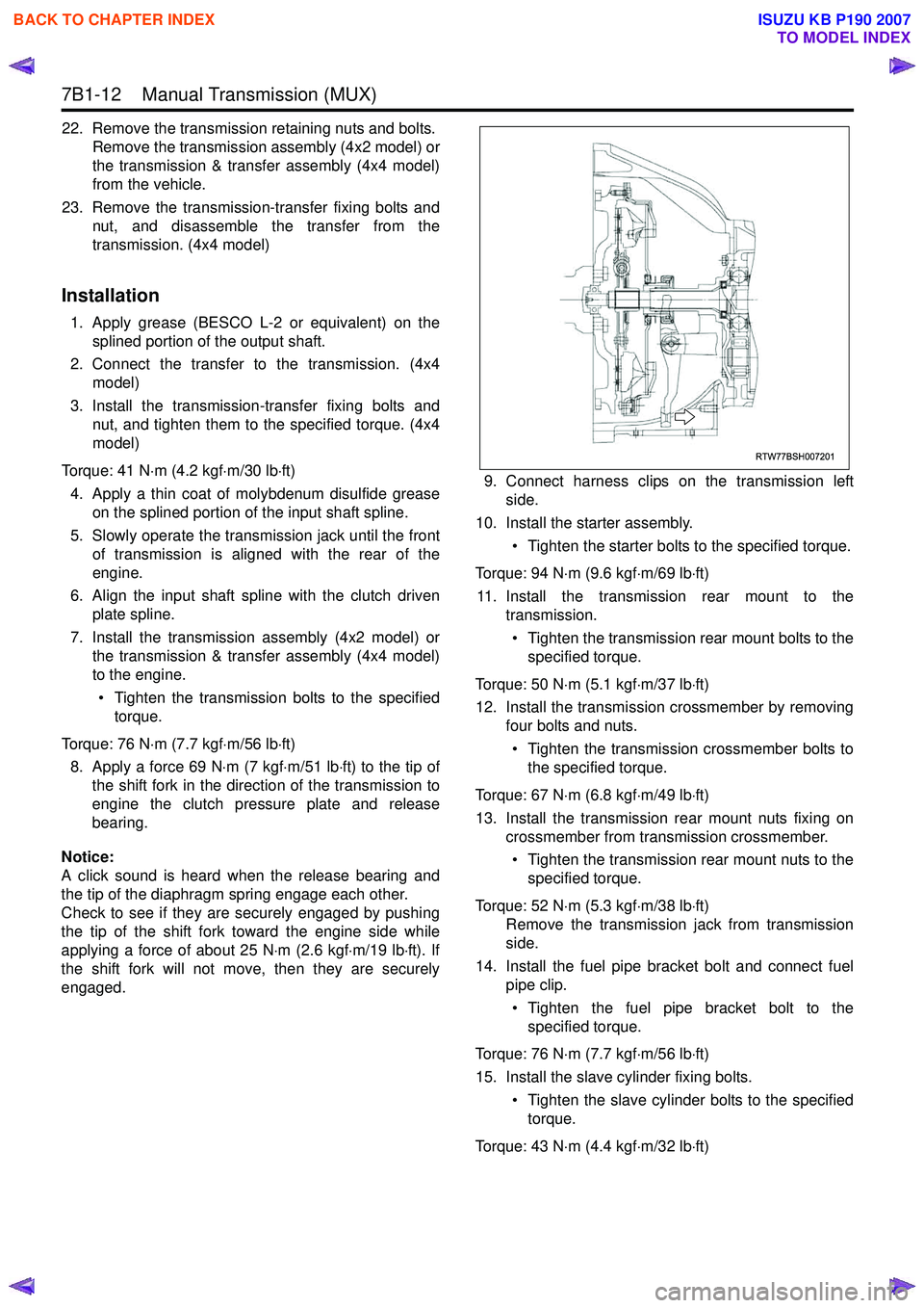
8. Apply a force 69 N ⋅m (7 kgf ⋅m/51 lb ⋅ft) to the tip of
the shift fork in the direction of the transmission to
engine the clutch pressure plate and release
bearing.
Notice:
A click sound is heard when the release bearing and
the tip of the diaphragm spring engage each other.
Check to see if they are securely engaged by pushing
the tip of the shift fork toward the engine side while
applying a force of about 25 N ⋅m (2.6 kgf ⋅m/19 lb ⋅ft). If
the shift fork will not move, then they are securely
engaged. 9. Connect harness clips on the transmission left
side.
10. Install the starter assembly.
• Tighten the starter bolts to the specified torque.
Torque: 94 N ⋅m (9.6 kgf ⋅m/69 lb ⋅ft)
11. Install the transmission rear mount to the transmission.
• Tighten the transmission rear mount bolts to the specified torque.
Torque: 50 N ⋅m (5.1 kgf ⋅m/37 lb ⋅ft)
12. Install the transmission crossmember by removing four bolts and nuts.
• Tighten the transmission crossmember bolts to the specified torque.
Torque: 67 N ⋅m (6.8 kgf ⋅m/49 lb ⋅ft)
13. Install the transmission rear mount nuts fixing on crossmember from transmission crossmember.
• Tighten the transmission rear mount nuts to the specified torque.
Torque: 52 N ⋅m (5.3 kgf ⋅m/38 lb ⋅ft)
Remove the transmission jack from transmission
side.
14. Install the fuel pipe bracket bolt and connect fuel pipe clip.
• Tighten the fuel pipe bracket bolt to the specified torque.
Torque: 76 N ⋅m (7.7 kgf ⋅m/56 lb ⋅ft)
15. Install the slave cylinder fixing bolts. • Tighten the slave cylinder bolts to the specifiedtorque.
Torque: 43 N ⋅m (4.4 kgf ⋅m/32 lb ⋅ft)
RTW77BSH007201
BACK TO CHAPTER INDEX
TO MODEL INDEX
ISUZU KB P190 2007
Page 4752 of 6020
Manual Transmission (MUX) 7B1-33
63. Install the front cover.• Tighten the front cover bolts to the specifiedtorque.
Torque: 23 N ⋅m (2.3 kgf ⋅m/17 lb ⋅ft)
64. After reassembling the transmission, refill the case with the new specified transmission oil.
a. Install the drain plug with new gasket. • Never reinstall the used gasket.
• Apply engine oil to the new gasket surface.
• Tighten the drain plug to the specified torque.
Torque: 39 N ⋅m (4.0 kgf ⋅m/29 lb ⋅ft)
b. Remove the filler plug with gasket.
c. Refill the case with the new specified transmission oil (BESCO Trans Axle Oil 5W-30
SF) amount 3.0 liters.
d. Install the filler plug with new gasket. • Never reinstall the used gasket.
• Apply engine oil to the new gasket surface.
• Tighten the filler plug to the specified torque.
Torque: 39 N ⋅m (4.0 kgf ⋅m/29 lb ⋅ft)
BACK TO CHAPTER INDEX
TO MODEL INDEX
ISUZU KB P190 2007
Page 4957 of 6020
ELECTRICAL-BODY AND CHASSIS 8A-19
Battery-1
BATTERY
Inspection
1. Check the battery terminals 1 for corrosion.
2. Check the battery cables
2 for looseness.
3. Check the battery case
3 for cracks and other damage.
4. Check the battery electrolyte level.
Battery-2
Battery Replacement
1. Disconnect the battery ground cable 1.
2. Disconnect the battery positive cable
2.
3. Remove the battery clamp
3.
4. Remove the battery
Caution:
It is important that the battery ground cable be removed
first.
Removing the battery positive cable first can result in a
short circuit.
Jump Starting the Engine with a Booster Battery
The following description assumes that you are using a booster
battery mounted on a second vehicle.
The listed steps (with some minor modifications) are also
applicable if you are using a naked booster battery or special
battery charging equipment.
BACK TO CHAPTER INDEX TO MODEL INDEXISUZU KB P190 2007
Page 4958 of 6020

8A-20 ELECTRICAL-BODY AND CHASSIS
Caution:
Never push or tow the vehicle in an attempt to start it.
Extensive damage to the emission system and other
vehicle parts will result.
(Only catalytic converter vehicle)
Treat both the discharged battery and the booster battery
with great care when using jumper cables.
Carefully follow the procedure outlined below.
Always be aware of the dangers of sparking.
Failure to follow the following procedure can result in:
a. Serious personal injury, specially to your eyes.
b. Extensive property damage from a battery explosion, battery acid discharge, or electrical file.
c. Extensive damage to the electronic components o
f
both vehicles.
Do not use a 24 volt booster battery.
Serious damage to the vehicle's electrical system and
electronic components will result.
Jump Starting Procedure
1. Set the parking brake on both vehicles.
2. If one or both vehicles is equipped with a manual transmission, place the gear shift in the "NEUTRAL"
position.
3. Turn off the ignition on both vehicles.
4. Turn off all vehicle lights and accessories.
5 Be sure that the two vehicles are not touching.
Attach the end of one jumper cable to the booster battery
positive terminal.
6
Attach the other end of the same cable to the discharged
battery positive terminal.
7. Once again, check that the booster battery has a 12 volt rating.
8.
Attach one end of the remaining booster cable to the
booster battery negative terminal.
9.
Attach the other end of the booster cable to a solid ground
(such as the air conditioner compressor mounting bracket
or the alternator mounting bracket) in the engine room o
f
the vehicle with the discharged battery.
10.Be sure that the ground connection is at least 500 mm (20 in) from the discharged battery.
BACK TO CHAPTER INDEX TO MODEL INDEXISUZU KB P190 2007