2007 ISUZU KB P190 engine mount
[x] Cancel search: engine mountPage 3812 of 6020
Automatic Transmission – 4L60E – Electrical Diagnosis Page 7C2–26
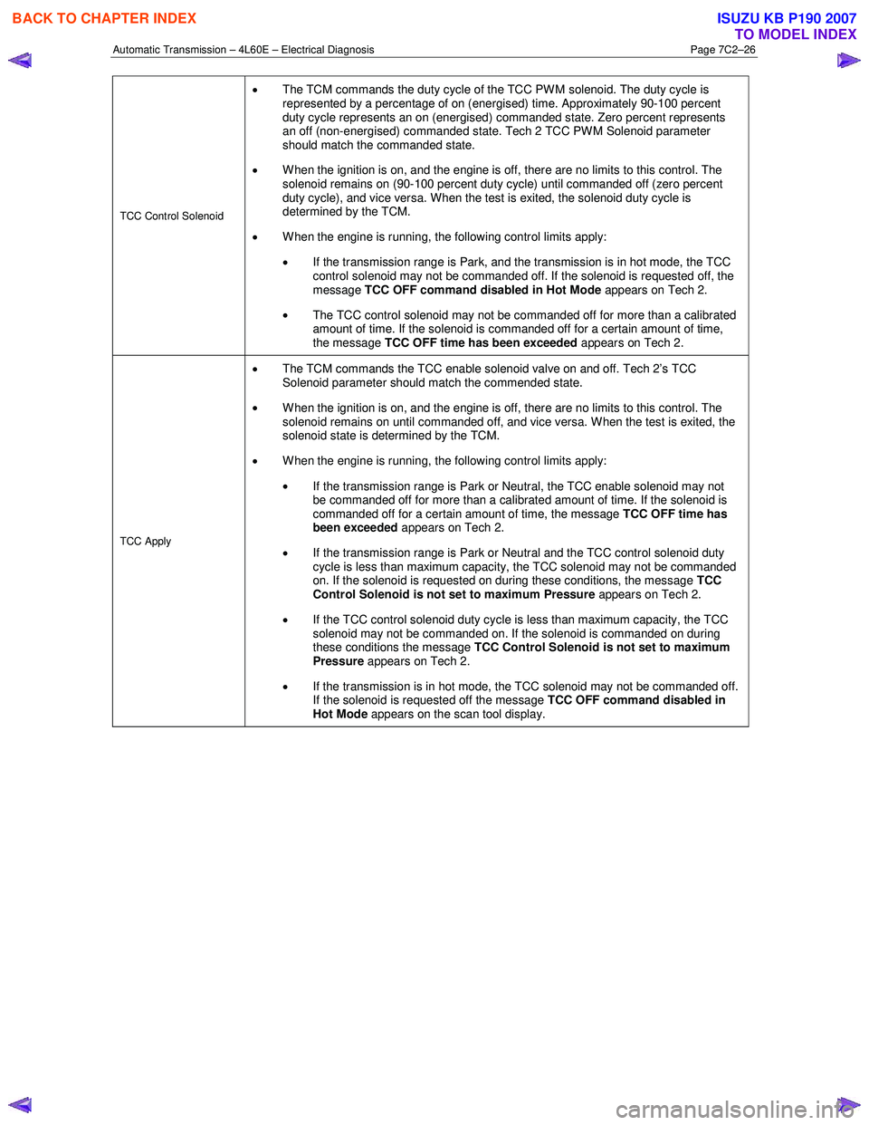
TCC Control Solenoid
• The TCM commands the duty cycle of the TCC PWM solenoid. The duty cycle is
represented by a percentage of on (energised) time. Approximately 90-100 percent
duty cycle represents an on (energised) commanded state. Zero percent represents
an off (non-energised) commanded state. Tech 2 TCC PW M Solenoid parameter
should match the commanded state.
• When the ignition is on, and the engine is off, there are no limits to this control. The
solenoid remains on (90-100 percent duty cycle) until commanded off (zero percent
duty cycle), and vice versa. When the test is exited, the solenoid duty cycle is
determined by the TCM.
• W hen the engine is running, the following control limits apply:
• If the transmission range is Park, and the transmission is in hot mode, the TCC
control solenoid may not be commanded off. If the solenoid is requested off, the
message TCC OFF command disabled in Hot Mode appears on Tech 2.
• The TCC control solenoid may not be commanded off for more than a calibrated
amount of time. If the solenoid is commanded off for a certain amount of time,
the message TCC OFF time has been exceeded appears on Tech 2.
TCC Apply
•
The TCM commands the TCC enable solenoid valve on and off. Tech 2’s TCC
Solenoid parameter should match the commended state.
• When the ignition is on, and the engine is off, there are no limits to this control. The
solenoid remains on until commanded off, and vice versa. W hen the test is exited, the
solenoid state is determined by the TCM.
• W hen the engine is running, the following control limits apply:
• If the transmission range is Park or Neutral, the TCC enable solenoid may not
be commanded off for more than a calibrated amount of time. If the solenoid is
commanded off for a certain amount of time, the message TCC OFF time has
been exceeded appears on Tech 2.
• If the transmission range is Park or Neutral and the TCC control solenoid duty
cycle is less than maximum capacity, the TCC solenoid may not be commanded
on. If the solenoid is requested on during these conditions, the message TCC
Control Solenoid is not set to maximum Pressure appears on Tech 2.
• If the TCC control solenoid duty cycle is less than maximum capacity, the TCC
solenoid may not be commanded on. If the solenoid is commanded on during
these conditions the message TCC Control Solenoid is not set to maximum
Pressure appears on Tech 2.
• If the transmission is in hot mode, the TCC solenoid may not be commanded off.
If the solenoid is requested off the message TCC OFF command disabled in
Hot Mode appears on the scan tool display.
BACK TO CHAPTER INDEX
TO MODEL INDEX
ISUZU KB P190 2007
Page 3814 of 6020
Automatic Transmission – 4L60E – Electrical Diagnosis Page 7C2–28
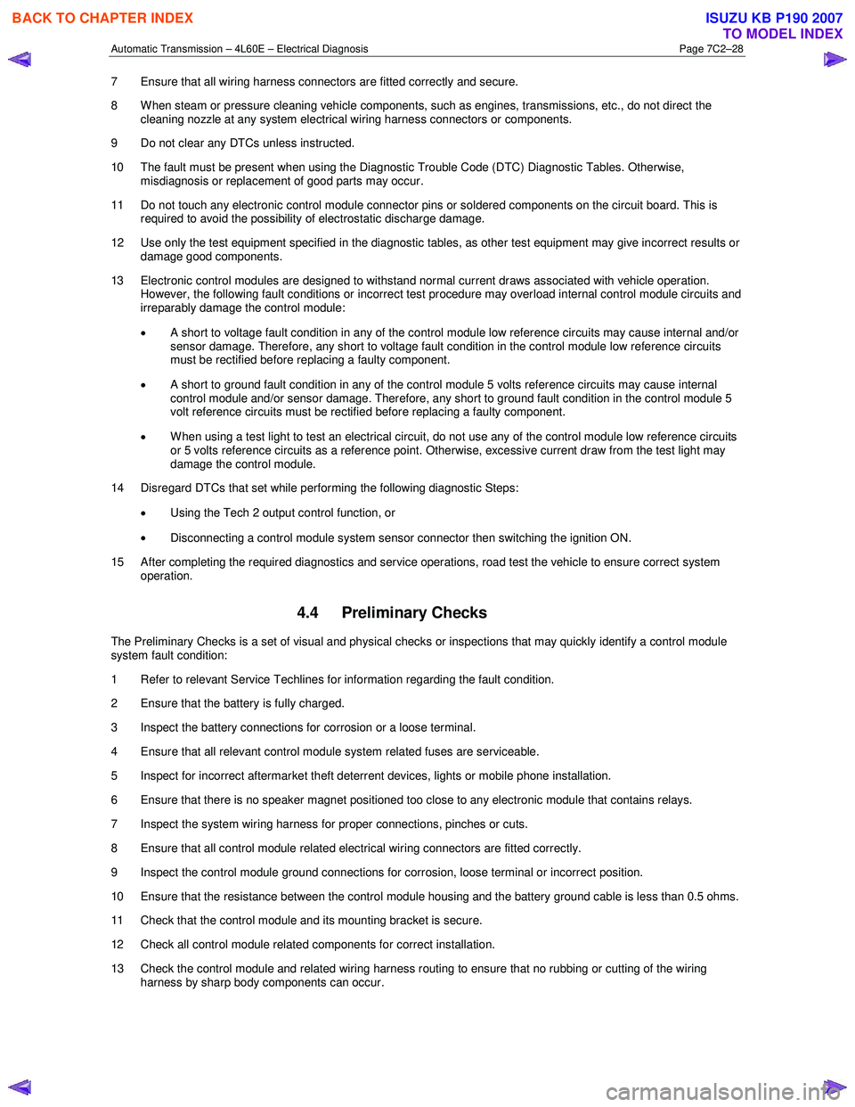
7 Ensure that all wiring harness connectors are fitted correctly and secure.
8 W hen steam or pressure cleaning vehicle components, such as engines, transmissions, etc., do not direct the cleaning nozzle at any system electrical wiring harness connectors or components.
9 Do not clear any DTCs unless instructed.
10 The fault must be present when using the Diagnostic Trouble Code (DTC) Diagnostic Tables. Otherwise, misdiagnosis or replacement of good parts may occur.
11 Do not touch any electronic control module connector pins or soldered components on the circuit board. This is required to avoid the possibility of electrostatic discharge damage.
12 Use only the test equipment specified in the diagnostic tables, as other test equipment may give incorrect results or damage good components.
13 Electronic control modules are designed to withstand normal current draws associated with vehicle operation. However, the following fault conditions or incorrect test procedure may overload internal control module circuits and
irreparably damage the control module:
• A short to voltage fault condition in any of the control module low reference circuits may cause internal and/or
sensor damage. Therefore, any short to voltage fault condition in the control module low reference circuits
must be rectified before replacing a faulty component.
• A short to ground fault condition in any of the control module 5 volts reference circuits may cause internal
control module and/or sensor damage. Therefore, any short to ground fault condition in the control module 5
volt reference circuits must be rectified before replacing a faulty component.
• W hen using a test light to test an electrical circuit, do not use any of the control module low reference circuits
or 5 volts reference circuits as a reference point. Otherwise, excessive current draw from the test light may
damage the control module.
14 Disregard DTCs that set while performing the following diagnostic Steps:
• Using the Tech 2 output control function, or
• Disconnecting a control module system sensor connector then switching the ignition ON.
15 After completing the required diagnostics and service operations, road test the vehicle to ensure correct system operation.
4.4 Preliminary Checks
The Preliminary Checks is a set of visual and physical checks or inspections that may quickly identify a control module
system fault condition:
1 Refer to relevant Service Techlines for information regarding the fault condition.
2 Ensure that the battery is fully charged.
3 Inspect the battery connections for corrosion or a loose terminal.
4 Ensure that all relevant control module system related fuses are serviceable.
5 Inspect for incorrect aftermarket theft deterrent devices, lights or mobile phone installation.
6 Ensure that there is no speaker magnet positioned too close to any electronic module that contains relays.
7 Inspect the system wiring harness for proper connections, pinches or cuts.
8 Ensure that all control module related electrical wiring connectors are fitted correctly.
9 Inspect the control module ground connections for corrosion, loose terminal or incorrect position.
10 Ensure that the resistance between the control module housing and the battery ground cable is less than 0.5 ohms.
11 Check that the control module and its mounting bracket is secure.
12 Check all control module related components for correct installation.
13 Check the control module and related wiring harness routing to ensure that no rubbing or cutting of the wiring harness by sharp body components can occur.
BACK TO CHAPTER INDEX
TO MODEL INDEX
ISUZU KB P190 2007
Page 3835 of 6020
Automatic Transmission – 4L60E – Electrical Diagnosis Page 7C2–49
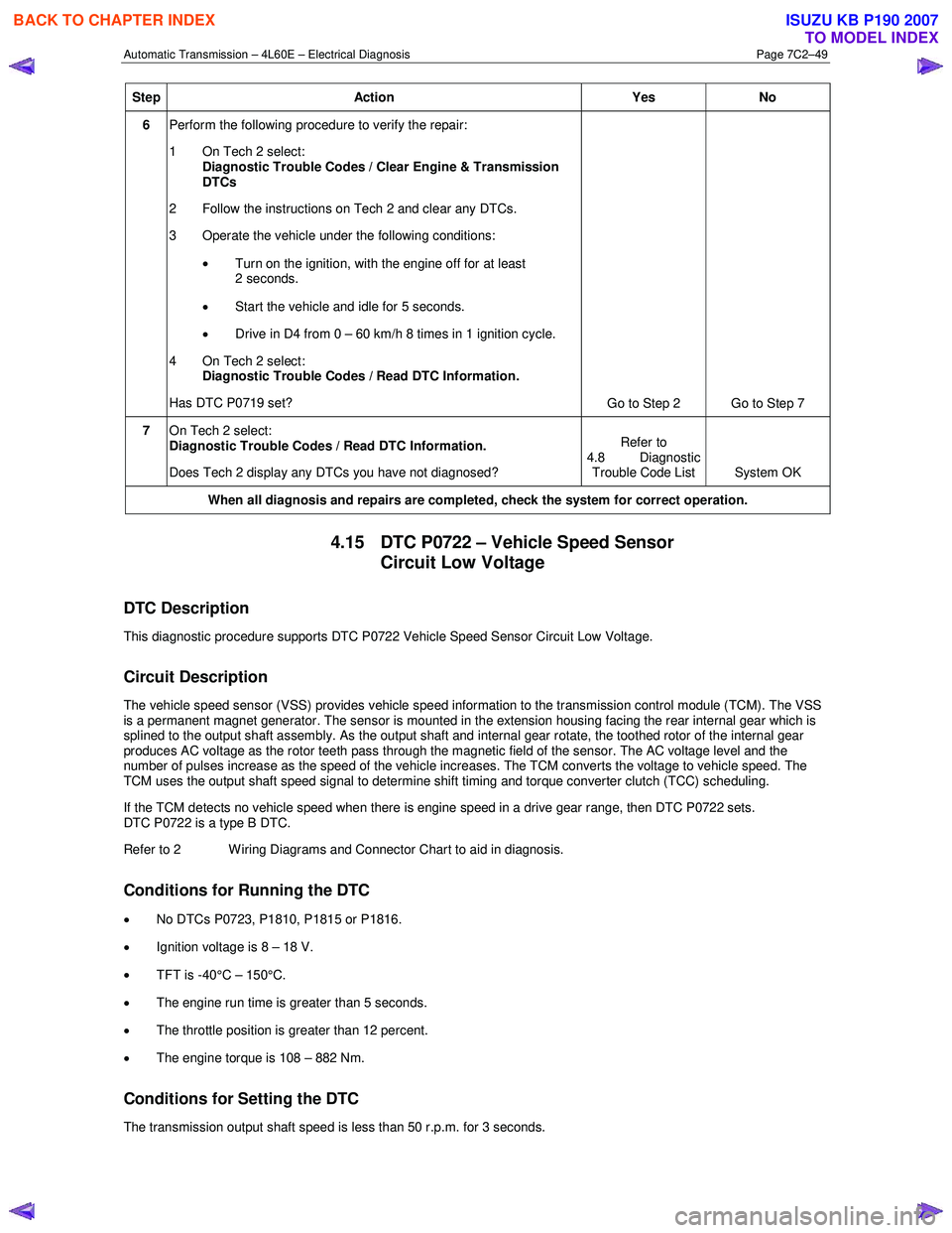
Step Action Yes No
6 Perform the following procedure to verify the repair:
1 On Tech 2 select: Diagnostic Trouble Codes / Clear Engine & Transmission
DTCs
2 Follow the instructions on Tech 2 and clear any DTCs.
3 Operate the vehicle under the following conditions:
• Turn on the ignition, with the engine off for at least
2 seconds.
• Start the vehicle and idle for 5 seconds.
• Drive in D4 from 0 – 60 km/h 8 times in 1 ignition cycle.
4 On Tech 2 select:
Diagnostic Trouble Codes / Read DTC Information.
Has DTC P0719 set? Go to Step 2 Go to Step 7
7 On Tech 2 select:
Diagnostic Trouble Codes / Read DTC Information.
Does Tech 2 display any DTCs you have not diagnosed? Refer to
4.8 Diagnostic Trouble Code List System OK
When all diagnosis and repairs are completed, check the
system for correct operation.
4.15 DTC P0722 – Vehicle Speed Sensor
Circuit Low Voltage
DTC Description
This diagnostic procedure supports DTC P0722 Vehicle Speed Sensor Circuit Low Voltage.
Circuit Description
The vehicle speed sensor (VSS) provides vehicle speed information to the transmission control module (TCM). The VSS
is a permanent magnet generator. The sensor is mounted in the extension housing facing the rear internal gear which is
splined to the output shaft assembly. As the output shaft and internal gear rotate, the toothed rotor of the internal gear
produces AC voltage as the rotor teeth pass through the magnetic field of the sensor. The AC voltage level and the
number of pulses increase as the speed of the vehicle increases. The TCM converts the voltage to vehicle speed. The
TCM uses the output shaft speed signal to determine shift timing and torque converter clutch (TCC) scheduling.
If the TCM detects no vehicle speed when there is engine speed in a drive gear range, then DTC P0722 sets.
DTC P0722 is a type B DTC.
Refer to 2 W iring Diagrams and Connector Chart to aid in diagnosis.
Conditions for Running the DTC
• No DTCs P0723, P1810, P1815 or P1816.
• Ignition voltage is 8 – 18 V.
• TFT is -40°C – 150°C.
• The engine run time is greater than 5 seconds.
• The throttle position is greater than 12 percent.
• The engine torque is 108 – 882 Nm.
Conditions for Setting the DTC
The transmission output shaft speed is less than 50 r.p.m. for 3 seconds.
BACK TO CHAPTER INDEX
TO MODEL INDEX
ISUZU KB P190 2007
Page 3838 of 6020
Automatic Transmission – 4L60E – Electrical Diagnosis Page 7C2–52
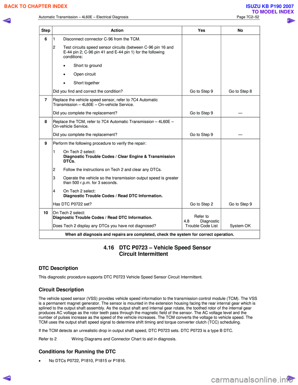
Step Action Yes No
6 1 Disconnect connector C-96 from the TCM.
2 Test circuits speed sensor circuits (between C-96 pin 16 and E-44 pin 2; C-96 pin 41 and E-44 pin 1) for the following
conditions:
• Short to ground
• Open circuit
• Short together
Did you find and correct the condition? Go to Step 9 Go to Step 8
7 Replace the vehicle speed sensor, refer to 7C4 Automatic
Transmission – 4L60E – On-vehicle Service.
Did you complete the replacement? Go to Step 9 —
8 Replace the TCM, refer to 7C4 Automatic Transmission – 4L60E –
On-vehicle Service.
Did you complete the replacement? Go to Step 9 —
9 Perform the following procedure to verify the repair:
1 On Tech 2 select: Diagnostic Trouble Codes / Clear Engine & Transmission
DTCs.
2 Follow the instructions on Tech 2 and clear any DTCs.
3 Operate the vehicle so the transmission output speed is greater than 500 r.p.m. for 3 seconds.
4 On Tech 2 select:
Diagnostic Trouble Codes / Read DTC Information.
Has DTC P0722 set? Go to Step 2 Go to Step 9
10 On Tech 2 select:
Diagnostic Trouble Codes / Read DTC Information.
Does Tech 2 display any DTCs you have not diagnosed? Refer to
4.8 Diagnostic Trouble Code List System OK
When all diagnosis and repairs are completed, check the system for correct operation.
4.16 DTC P0723 – Vehicle Speed Sensor
Circuit Intermittent
DTC Description
This diagnostic procedure supports DTC P0723 Vehicle Speed Sensor Circuit Intermittent.
Circuit Description
The vehicle speed sensor (VSS) provides vehicle speed information to the transmission control module (TCM). The VSS
is a permanent magnet generator. The sensor is mounted in the extension housing facing the rear internal gear which is
splined to the output shaft assembly. As the output shaft and internal gear rotate, the toothed rotor of the internal gear
produces AC voltage as the rotor teeth pass through the magnetic field of the sensor. The AC voltage level and the
number of pulses increase as the speed of the vehicle increases. The TCM converts the voltage to vehicle speed. The
TCM uses the output shaft speed signal to determine shift timing and torque converter clutch (TCC) scheduling.
If the TCM detects an unrealistic drop in output shaft speed, DTC P0723 sets. DTC P0723 is a type B DTC.
Refer to 2 W iring Diagrams and Connector Chart to aid in diagnosis.
Conditions for Running the DTC
• No DTCs P0722, P1810, P1815 or P1816.
BACK TO CHAPTER INDEX
TO MODEL INDEX
ISUZU KB P190 2007
Page 3872 of 6020
Automatic Transmission – 4L60E – Electrical Diagnosis Page 7C2–86
Step Action Yes No
14 Perform the following procedure to verify the repair:
1 On Tech 2 select: Diagnostic Trouble Codes / Clear Engine & Transmission
DTCs.
2 Follow the instructions on Tech 2 and clear any DTCs.
3 On Tech 2 select: Automatic Transmission / Data Display / Transmission Data.
4 Operate the vehicle under the following conditions:
• Drive the vehicle in D4, with the TCC on, and a throttle
position at 20%.
• On Tech 2 ensure the TCC Slip Speed is -20 to +50 RPM
for at least 7 seconds.
5 On Tech 2 select:
Diagnostic Trouble Codes / Read DTC Information.
Has DTC P0894 set? Go to Step 2 Go to Step 15
15 On Tech 2 select:
Diagnostic Trouble Codes / Read DTC Information.
Does Tech 2 display any DTCs you have not diagnosed? Refer to
4.8 Diagnostic Trouble Code List System OK
When all diagnosis and repairs are completed, check the system for correct operation.
4.27 DTC P0961 – Line Pressure Control
Solenoid System Performance
DTC Description
This diagnostic procedure supports DTC P0961 Line Pressure Control (PC) Solenoid System Performance.
Circuit Description
The pressure control (PC) solenoid valve is an electronic device that regulates transmission line pressure based on the
current flow through its coil winding. The magnetic field produced by the coil moves the solenoid's internal valve, which
varies pressure to the pressure regulator valve. The transmission control module (TCM) controls the PC solenoid valve
by applying a varying amount of current to the solenoid. The applied current can vary from 0.1 – 1.1 A. Low current,
0.1 A, indicates high line pressure. High current, 1.1 A, indicates low line pressure. The duty cycle of the PC solenoid
valve is expressed as a percentage of energised on time. Zero percent indicates zero on time, non-energised, or no
current flow. Approximately 60 percent at idle indicates maximum on time, energised, or high current flow. The TCM
determines the appropriate line pressure for a given load by comparing the throttle position, the engine speed and other
inputs.
W hen the TCM detects a continuous open or short to ground in the PC solenoid valve circuit, then DTC P0961 sets.
DTC P0961 is a type C DTC.
Refer to 2 W iring Diagrams and Connector Chart to aid in diagnosis.
Conditions for Running the DTC
• The system voltage is 8 – 18 V.
• The engine is running.
Conditions for Setting the DTC
The PC solenoid valve duty cycle reaches its high limit, approximately 95 percent, or low limit, approximately 2 percent.
Action Taken When the DTC Sets
• The TCM does not request the engine control module (ECM) to illuminate the MIL.
BACK TO CHAPTER INDEX
TO MODEL INDEX
ISUZU KB P190 2007
Page 3889 of 6020
Automatic Transmission – 4L60E – Electrical Diagnosis Page 7C2–103
Step Action Yes No
6 Using a multimeter, test between E-95 pin 3 and C-96 pin 30 for a
short to voltage.
Did you find and correct the condition? Go to Step 8 Go to Step 7
7 Replace the TCM, refer to 7C4 Automatic Transmission – 4L60E –
On-vehicle Servicing
Did you complete the replacement? Go to Step 8 —
8 Perform the following procedure to verify the repair:
1 On Tech 2 select: Diagnostic Trouble Codes / Clear Engine & Transmission
DTCs.
2 Follow the instructions on Tech 2 and clear any DTCs.
3 On Tech 2 select: Data Display / 2-3 Shift Data.
4 Drive the vehicle in D4 and ensure the following conditions are met::
• The TCM commands the Shift Solenoid B On and the
Shift Solenoid B Circuit status parameter displays Okay.
• The TCM commands the Shift Solenoid B Off and the
Shift Solenoid B Circuit status parameter displays Okay.
• All conditions are met for 5 seconds.
4 On Tech 2 select:
Diagnostic Trouble Codes / Read DTC Information.
Has DTC P0977 set? Go to Step 2 Go to Step 9
9 On Tech 2 select:
Diagnostic Trouble Codes / Read DTC Information.
Does Tech 2 display any DTCs you have not diagnosed? Refer to
4.8 Diagnostic Trouble Code List System OK
When all diagnosis and repairs are completed, check the
system for correct operation.
4.32 DTC P1810, P1815 and P1816 –
Transmission Fluid Pressure Position
Switch
DTC Description
This diagnostic procedure supports the following DTCs:
• DTC P1810 Transmission Fluid Pressure (TFP) Position Switch Circuit.
• DTC P1815 Transmission Fluid Pressure (TFP) Valve Position Switch – Start in W rong Range.
• DTC P1816 Transmission Fluid Pressure (TFP) Valve Position Switch Indicates Park/Neutral (P/N) with Drive Ratio.
Circuit Description
The automatic transmission fluid pressure (TFP) manual valve position switch consists of five pressure switches
(two normally-closed and three normally-open) and a transmission fluid temperature (TFT) sensor combined into one unit.
The combined unit mounts on the valve body. The transmission control module (TCM) supplies ignition voltage for each
range signal. By grounding one or more of these circuits through various combinations of the pressure switches, the
TCM detects which manual valve position you select. The TCM compares the actual voltage combination of the switches
to a TFP manual valve position switch combination chart stored in memory.
The TFP manual valve position switch cannot distinguish between park and neutral because the monitored valve body
pressures are identical. W ith the engine off and the ignition switch on, the TFP manual valve position switch indicates
BACK TO CHAPTER INDEX
TO MODEL INDEX
ISUZU KB P190 2007
Page 3953 of 6020

Automatic Transmission – 4L60E – On-vehicle Servicing Page 7C4–40
5 Remove the filler tube from the engine compartment.
6 Remove the filler tube seal from the transmission case and discard.
7 If the breather hose needs to be replaced proceed as follows: a unclip the breather hose (4) from the harness channel (5).
b Remove the transmission support and lower the rear of the transmission sufficiently to get access to the breather hose, refer to 3.7 Transmission Support and Mount.
c Disconnect the breather hose from the T-joint (6) and the top of the transmission case and remove.
d If required, remove the two bolts (7) attaching the brackets of the vent pipe (8) to the chassis, disconnect from the T-joint and remove the vent pipe.
Figure 7C4 – 57
Reinstall
Reinstallation of the transmission filler tube and/or the breather hose is the reverse of the removal procedure, noting the
following:
1 Smear a new filler tube seal with clean transmission fluid and fit it to the transmission case.
2 Ensure the transmission breather hose and the harness are secured to the filler tube lower bracket.
3 Tighten the bolt attaching the filler tube bracket to the correct torque specification.
Filler tube bracket attaching bolt
torque specification ................................. 20.0 – 35.0 Nm
4 If required, tighten the two bolts attaching the vent pipe bracket to the chassis to the correct torque specification.
Vent pipe attaching bolt
torque specification ..............................................6.0 Nm
BACK TO CHAPTER INDEX
TO MODEL INDEX
ISUZU KB P190 2007
Page 3954 of 6020
Automatic Transmission – 4L60E – On-vehicle Servicing Page 7C4–41
3.17 Transmission Cooler Line/Hose
Assemblies
Remove
1 Disconnect the transmission cooler hose/line assemblies from the radiator quick connect fittings as
follows:
a Pull back the verifier disc (1) from the quick connect fitting (2) and slide it back along the line.
b Open the release tool, Tool No J-41623-B (3), slip it over the cooler line to be disconnected
from the radiator, ahead of the verifier disc.
c Slide the release tool along the cooler line and engage it with the quick-connect fitting.
d W hile pushing inwards, rotate clockwise the release tool about one sixth of a turn to release
the spring clip holding the cooler line.
e With the release tool held in this position, pull back on the cooler line to release it.
f Plug the openings to prevent fluid loss and/or contamination.
g Repeat the procedure to remove the remaining cooler line.
NOTE
If the spring clip and/or O-ring seal in the quick-
connect fitting is damaged during the removal
process, the complete fitting must be replaced.
2 Unclip the outlet cooler line (4) from the radiator fan shroud (5).
Figure 7C4 – 58
3 Remove the screw (1) attaching the transmission cooler line bracket (2) to the right-hand side of the
engine.
Figure 7C4 – 59
4 Remove the transmission support, refer to 3.7 Transmission Support and Mount.
BACK TO CHAPTER INDEX
TO MODEL INDEX
ISUZU KB P190 2007