2007 ISUZU KB P190 brake
[x] Cancel search: brakePage 3789 of 6020
Automatic Transmission – 4L60E – Electrical Diagnosis Page 7C2–3
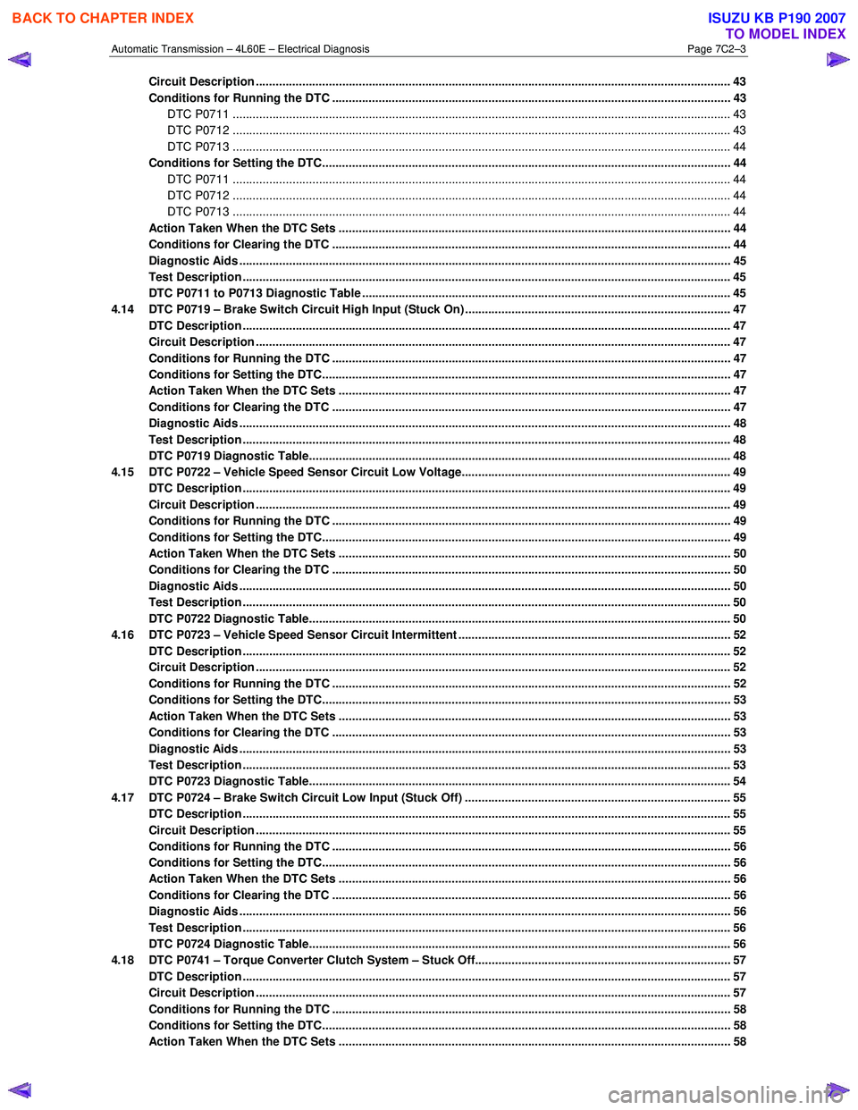
Circuit Description ............................................................................................................................................... 43
Conditions for Running the DTC ........................................................................................................................ 43
DTC P0711 ...................................................................................................................................................... 43
DTC P0712 ...................................................................................................................................................... 43
DTC P0713 ...................................................................................................................................................... 44
Conditions for Setting the DTC................................................................................................. .......................... 44
DTC P0711 ...................................................................................................................................................... 44
DTC P0712 ...................................................................................................................................................... 44
DTC P0713 ...................................................................................................................................................... 44
Action Taken When the DTC Sets ................................................................................................. ..................... 44
Conditions for Clearing the DTC ........................................................................................................................ 44
Diagnostic Aids .................................................................................................................................................... 45
Test Description ................................................................................................................................................... 45
DTC P0711 to P0713 Diagnostic Table ............................................................................................ ................... 45
4.14 DTC P0719 – Brake Switch Circuit High Input (Stuck On) ......................................................................... ....... 47
DTC Description ................................................................................................................................................... 47
Circuit Description ............................................................................................................................................... 47
Conditions for Running the DTC ................................................................................................. ....................... 47
Conditions for Setting the DTC........................................................................................................................... 47
Action Taken When the DTC Sets ................................................................................................. ..................... 47
Conditions for Clearing the DTC ........................................................................................................................ 47
Diagnostic Aids .................................................................................................................................................... 48
Test Description ................................................................................................................................................... 48
DTC P0719 Diagnostic Table..................................................................................................... .......................... 48
4.15 DTC P0722 – Vehicle Speed Sensor Circuit Low Voltage........................................................................... ...... 49
DTC Description ................................................................................................................................................... 49
Circuit Description ............................................................................................................................................... 49
Conditions for Running the DTC ................................................................................................. ....................... 49
Conditions for Setting the DTC........................................................................................................................... 49
Action Taken When the DTC Sets ................................................................................................. ..................... 50
Conditions for Clearing the DTC ........................................................................................................................ 50
Diagnostic Aids .................................................................................................................................................... 50
Test Description ................................................................................................................................................... 50
DTC P0722 Diagnostic Table..................................................................................................... .......................... 50
4.16 DTC P0723 – Vehicle Speed Sensor Circuit Intermittent .......................................................................... ........ 52
DTC Description ................................................................................................................................................... 52
Circuit Description ............................................................................................................................................... 52
Conditions for Running the DTC ................................................................................................. ....................... 52
Conditions for Setting the DTC........................................................................................................................... 53
Action Taken When the DTC Sets ................................................................................................. ..................... 53
Conditions for Clearing the DTC ........................................................................................................................ 53
Diagnostic Aids .................................................................................................................................................... 53
Test Description ................................................................................................................................................... 53
DTC P0723 Diagnostic Table..................................................................................................... .......................... 54
4.17 DTC P0724 – Brake Switch Circuit Low Input (Stuck Off) ................................................................................ 55
DTC Description ................................................................................................................................................... 55
Circuit Description ............................................................................................................................................... 55
Conditions for Running the DTC ................................................................................................. ....................... 56
Conditions for Setting the DTC........................................................................................................................... 56
Action Taken When the DTC Sets ................................................................................................. ..................... 56
Conditions for Clearing the DTC ........................................................................................................................ 56
Diagnostic Aids .................................................................................................................................................... 56
Test Description ................................................................................................................................................... 56
DTC P0724 Diagnostic Table..................................................................................................... .......................... 56
4.18 DTC P0741 – Torque Converter Clutch System – Stuck Off......................................................................... .... 57
DTC Description ................................................................................................................................................... 57
Circuit Description ............................................................................................................................................... 57
Conditions for Running the DTC ................................................................................................. ....................... 58
Conditions for Setting the DTC........................................................................................................................... 58
Action Taken When the DTC Sets ................................................................................................. ..................... 58
BACK TO CHAPTER INDEX
TO MODEL INDEX
ISUZU KB P190 2007
Page 3796 of 6020
Automatic Transmission – 4L60E – Electrical Diagnosis Page 7C2–10
Limp Home Mode Description
If a major electrical system failure occurs which could affect vehicle safety or damage the transmission during normal
operation, the TCM enters a limp home mode. In the limp home mode, the transmission operates in the following
manner:
• The pressure control solenoid is off and the line pressure is at maximum to minimise clutch slippage.
• The TCC solenoid is off, therefore the torque converter clutch is disabled.
• The two shift solenoids are turned off. The transmission will operate in fourth gear if the vehicle has successfully
completed a 1-2 upshift in the current ignition cycle. If the vehicle has not completed a 1-2 upshift in the current
ignition cycle, the transmission will operate in third gear. If the transmission is operating in fourth gear, third gear
may be obtained if the engine is stopped briefly and re-started.
In limp home mode, the gear selector lever is ineffective at selecting forward gear ranges. In third or fourth gear, heat
builds up in the transmission quickly, particularly in stop and go traffic. Excessive heat build-up may cause transmission
failure if the vehicle is driven for extended distances in limp home mode.
1.3 Transmission Indicators and Messages
For information pertaining to the instrument cluster and the transmission information it displays, refer to the RA Rodeo
Owner Handbook.
1.4 Electronic Component Description
For all other electrical components not covered in this section, refer to General Motors Powertrain Group Electronically
Controlled Automatic Transmission Technician's Guide.
Transmission Control Module (TCM)
The Transmission Control Module (TCM) is located under the instrument panel, next to the brake pedal assembly and
connects directly to the transmission wiring harness. A single 49-way connector is used to make the connection between
the vehicle wiring harness and the TCM.
To access the connector for diagnosis:
1 Ensure the ignition switch is in the OFF position.
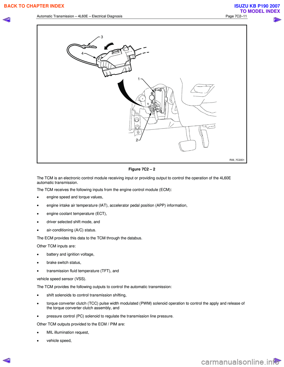
2 Disconnect the connector (1) from the transmission control module (TCM) (2) as follows, refer to Figure 7C2 – 2: a remove the securing pin (3),
b press the locking tab and swing the lever (4) to free the connector,
c remove the connector.
BACK TO CHAPTER INDEX
TO MODEL INDEX
ISUZU KB P190 2007
Page 3797 of 6020
Automatic Transmission – 4L60E – Electrical Diagnosis Page 7C2–11
Figure 7C2 – 2
The TCM is an electronic control module receiving input or providing output to control the operation of the 4L60E
automatic transmission.
The TCM receives the following inputs from the engine control module (ECM):
• engine speed and torque values,
• engine intake air temperature (IAT), accelerator pedal position (APP) information,
• engine coolant temperature (ECT),
• driver selected shift mode, and
• air-conditioning (A/C) status.
The ECM provides this data to the TCM through the databus.
Other TCM inputs are:
• battery and ignition voltage,
• brake switch status,
• transmission fluid temperature (TFT), and
vehicle speed sensor (VSS).
The TCM provides the following outputs to control the automatic transmission:
• shift solenoids to control transmission shifting,
• torque converter clutch (TCC) pulse width modulated (PW M) solenoid operation to control the apply and release of
the torque converter clutch assembly, and
• pressure control (PC) solenoid to regulate the transmission line pressure.
Other TCM outputs provided to the ECM / PIM are:
• MIL illumination request,
• vehicle speed,
BACK TO CHAPTER INDEX
TO MODEL INDEX
ISUZU KB P190 2007
Page 3818 of 6020
Automatic Transmission – 4L60E – Electrical Diagnosis Page 7C2–32
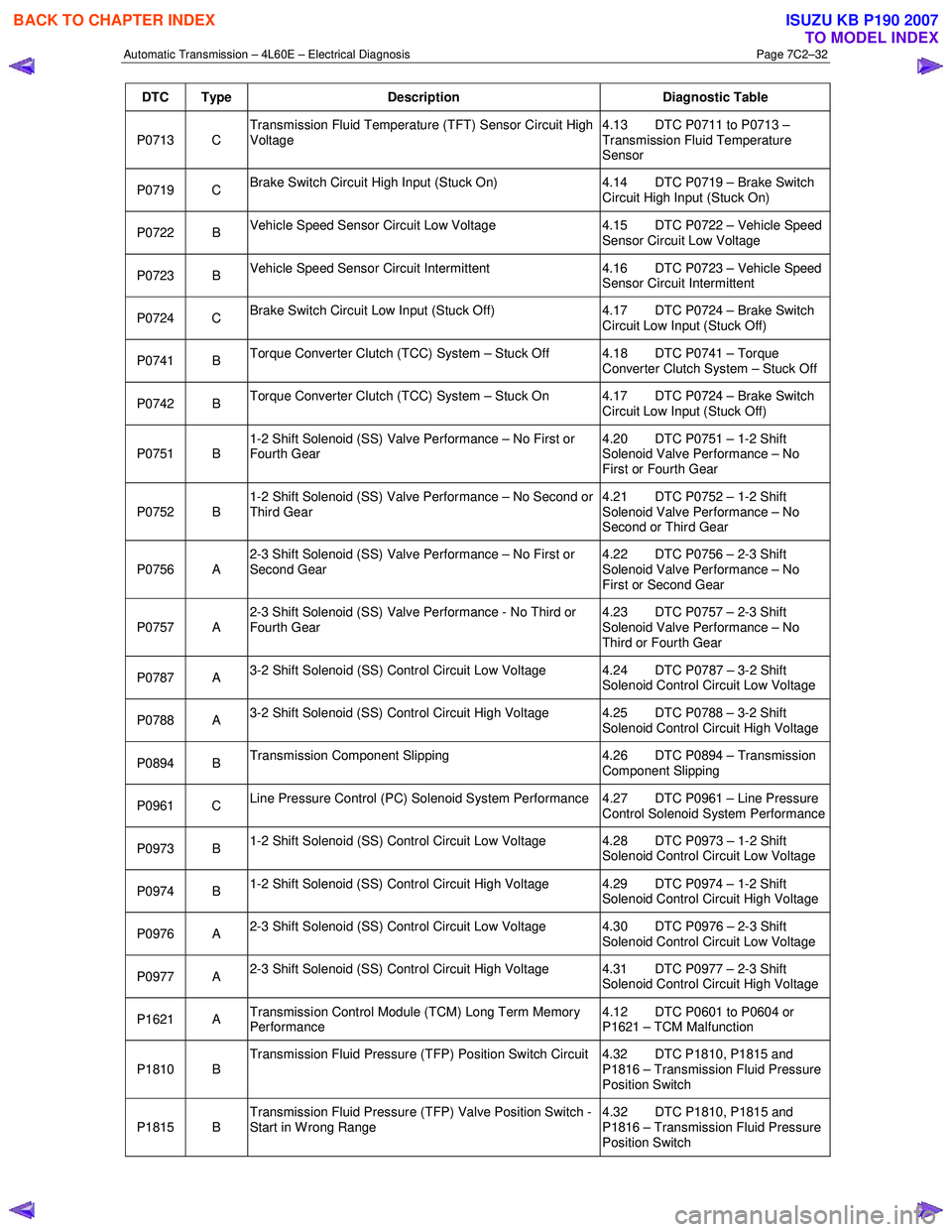
DTC Type Description Diagnostic Table
P0713 C Transmission Fluid Temperature (TFT) Sensor Circuit High
Voltage 4.13 DTC P0711 to P0713 –
Transmission Fluid Temperature
Sensor
P0719 C Brake Switch Circuit High Input (Stuck On) 4.14 DTC P0719 – Brake Switch
Circuit High Input (Stuck On)
P0722 B Vehicle Speed Sensor Circuit Low Voltage 4.15 DTC P0722 – Vehicle Speed
Sensor Circuit Low Voltage
P0723 B Vehicle Speed Sensor Circuit Intermittent 4.16 DTC P0723 – Vehicle Speed
Sensor Circuit Intermittent
P0724 C Brake Switch Circuit Low Input (Stuck Off) 4.17 DTC P0724 – Brake Switch
Circuit Low Input (Stuck Off)
P0741 B Torque Converter Clutch (TCC) System – Stuck Off 4.18 DTC P0741 – Torque
Converter Clutch System – Stuck Off
P0742 B Torque Converter Clutch (TCC) System – Stuck On 4.17 DTC P0724 – Brake Switch
Circuit Low Input (Stuck Off)
P0751 B 1-2 Shift Solenoid (SS) Valve Performance – No First or
Fourth Gear 4.20 DTC P0751 – 1-2 Shift
Solenoid Valve Performance – No
First or Fourth Gear
P0752 B 1-2 Shift Solenoid (SS) Valve Performance – No Second or
Third Gear 4.21 DTC P0752 – 1-2 Shift
Solenoid Valve Performance – No
Second or Third Gear
P0756 A 2-3 Shift Solenoid (SS) Valve Performance – No First or
Second Gear 4.22 DTC P0756 – 2-3 Shift
Solenoid Valve Performance – No
First or Second Gear
P0757 A 2-3 Shift Solenoid (SS) Valve Performance - No Third or
Fourth Gear 4.23 DTC P0757 – 2-3 Shift
Solenoid Valve Performance – No
Third or Fourth Gear
P0787 A 3-2 Shift Solenoid (SS) Control Circuit Low Voltage 4.24 DTC P0787 – 3-2 Shift
Solenoid Control Circuit Low Voltage
P0788 A 3-2 Shift Solenoid (SS) Control Circuit High Voltage 4.25 DTC P0788 – 3-2 Shift
Solenoid Control Circuit High Voltage
P0894 B Transmission Component Slipping 4.26 DTC P0894 – Transmission
Component Slipping
P0961 C Line Pressure Control (PC) Solenoid System Performance 4.27 DTC P0961 – Line Pressure
Control Solenoid System Performance
P0973 B 1-2 Shift Solenoid (SS) Control Circuit Low Voltage 4.28 DTC P0973 – 1-2 Shift
Solenoid Control Circuit Low Voltage
P0974 B 1-2 Shift Solenoid (SS) Control Circuit High Voltage 4.29 DTC P0974 – 1-2 Shift
Solenoid Control Circuit High Voltage
P0976 A 2-3 Shift Solenoid (SS) Control Circuit Low Voltage 4.30 DTC P0976 – 2-3 Shift
Solenoid Control Circuit Low Voltage
P0977 A 2-3 Shift Solenoid (SS) Control Circuit High Voltage 4.31 DTC P0977 – 2-3 Shift
Solenoid Control Circuit High Voltage
P1621 A Transmission Control Module (TCM) Long Term Memory
Performance 4.12 DTC P0601 to P0604 or
P1621 – TCM Malfunction
P1810 B Transmission Fluid Pressure (TFP) Position Switch Circuit 4.32 DTC P1810, P1815 and
P1816 – Transmission Fluid Pressure
Position Switch
P1815 B Transmission Fluid Pressure (TFP) Valve Position Switch -
Start in W rong Range 4.32 DTC P1810, P1815 and
P1816 – Transmission Fluid Pressure
Position Switch
BACK TO CHAPTER INDEX
TO MODEL INDEX
ISUZU KB P190 2007
Page 3833 of 6020
Automatic Transmission – 4L60E – Electrical Diagnosis Page 7C2–47
Step Action Yes No
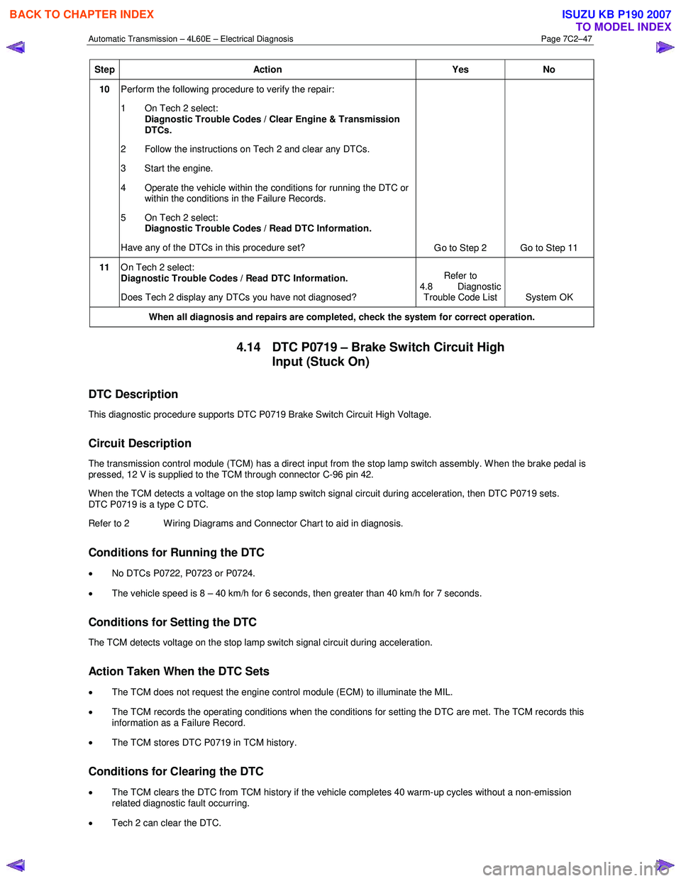
10 Perform the following procedure to verify the repair:
1 On Tech 2 select: Diagnostic Trouble Codes / Clear Engine & Transmission
DTCs.
2 Follow the instructions on Tech 2 and clear any DTCs.
3 Start the engine.
4 Operate the vehicle within the conditions for running the DTC or within the conditions in the Failure Records.
5 On Tech 2 select:
Diagnostic Trouble Codes / Read DTC Information.
Have any of the DTCs in this procedure set? Go to Step 2 Go to Step 11
11 On Tech 2 select:
Diagnostic Trouble Codes / Read DTC Information.
Does Tech 2 display any DTCs you have not diagnosed? Refer to
4.8 Diagnostic Trouble Code List System OK
When all diagnosis and repairs are completed, check the
system for correct operation.
4.14 DTC P0719 – Brake Switch Circuit High
Input (Stuck On)
DTC Description
This diagnostic procedure supports DTC P0719 Brake Switch Circuit High Voltage.
Circuit Description
The transmission control module (TCM) has a direct input from the stop lamp switch assembly. W hen the brake pedal is
pressed, 12 V is supplied to the TCM through connector C-96 pin 42.
W hen the TCM detects a voltage on the stop lamp switch signal circuit during acceleration, then DTC P0719 sets.
DTC P0719 is a type C DTC.
Refer to 2 W iring Diagrams and Connector Chart to aid in diagnosis.
Conditions for Running the DTC
• No DTCs P0722, P0723 or P0724.
• The vehicle speed is 8 – 40 km/h for 6 seconds, then greater than 40 km/h for 7 seconds.
Conditions for Setting the DTC
The TCM detects voltage on the stop lamp switch signal circuit during acceleration.
Action Taken When the DTC Sets
•
The TCM does not request the engine control module (ECM) to illuminate the MIL.
• The TCM records the operating conditions when the conditions for setting the DTC are met. The TCM records this
information as a Failure Record.
• The TCM stores DTC P0719 in TCM history.
Conditions for Clearing the DTC
• The TCM clears the DTC from TCM history if the vehicle completes 40 warm-up cycles without a non-emission
related diagnostic fault occurring.
• Tech 2 can clear the DTC.
BACK TO CHAPTER INDEX
TO MODEL INDEX
ISUZU KB P190 2007
Page 3834 of 6020
Automatic Transmission – 4L60E – Electrical Diagnosis Page 7C2–48
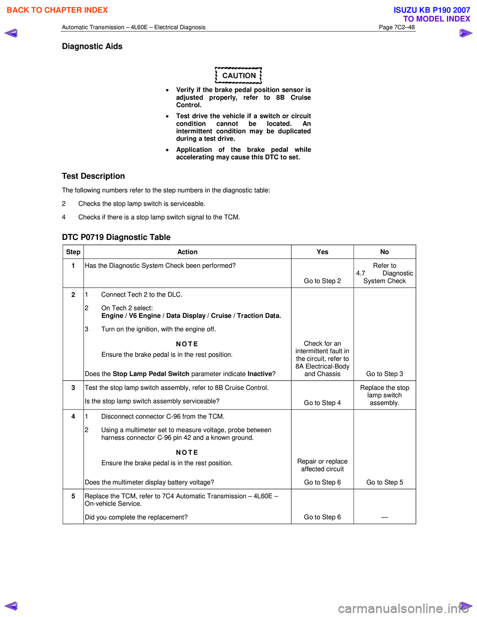
Diagnostic Aids
• Verify if the brake pedal position sensor is
adjusted properly, refer to 8B Cruise
Control.
• Test drive the vehicle if a switch or circuit
condition cannot be located. An
intermittent condition may be duplicated
during a test drive.
• Application of the brake pedal while
accelerating may cause this DTC to set.
Test Description
The following numbers refer to the step numbers in the diagnostic table:
2 Checks the stop lamp switch is serviceable.
4 Checks if there is a stop lamp switch signal to the TCM.
DTC P0719 Diagnostic Table
Step Action Yes No
1 Has the Diagnostic System Check been performed?
Go to Step 2 Refer to
4.7 Diagnostic System Check
2 1 Connect Tech 2 to the DLC.
2 On Tech 2 select: Engine / V6 Engine / Data Display / Cruise / Traction Data.
3 Turn on the ignition, with the engine off.
NOTE
Ensure the brake pedal is in the rest position.
Does the Stop Lamp Pedal Switch parameter indicate Inactive? Check for an
intermittent fault in
the circuit, refer to
8A Electrical-Body and Chassis Go to Step 3
3 Test the stop lamp switch assembly, refer to 8B Cruise Control.
Is the stop lamp switch assembly serviceable? Go to Step 4 Replace the stop
lamp switch
assembly.
4 1 Disconnect connector C-96 from the TCM.
2 Using a multimeter set to measure voltage, probe between harness connector C-96 pin 42 and a known ground.
NOTE
Ensure the brake pedal is in the rest position.
Does the multimeter display battery voltage? Repair or replace
affected circuit
Go to Step 6 Go to Step 5
5
Replace the TCM, refer to 7C4 Automatic Transmission – 4L60E –
On-vehicle Service.
Did you complete the replacement? Go to Step 6
—
BACK TO CHAPTER INDEX
TO MODEL INDEX
ISUZU KB P190 2007
Page 3841 of 6020
Automatic Transmission – 4L60E – Electrical Diagnosis Page 7C2–55
Step Action Yes No
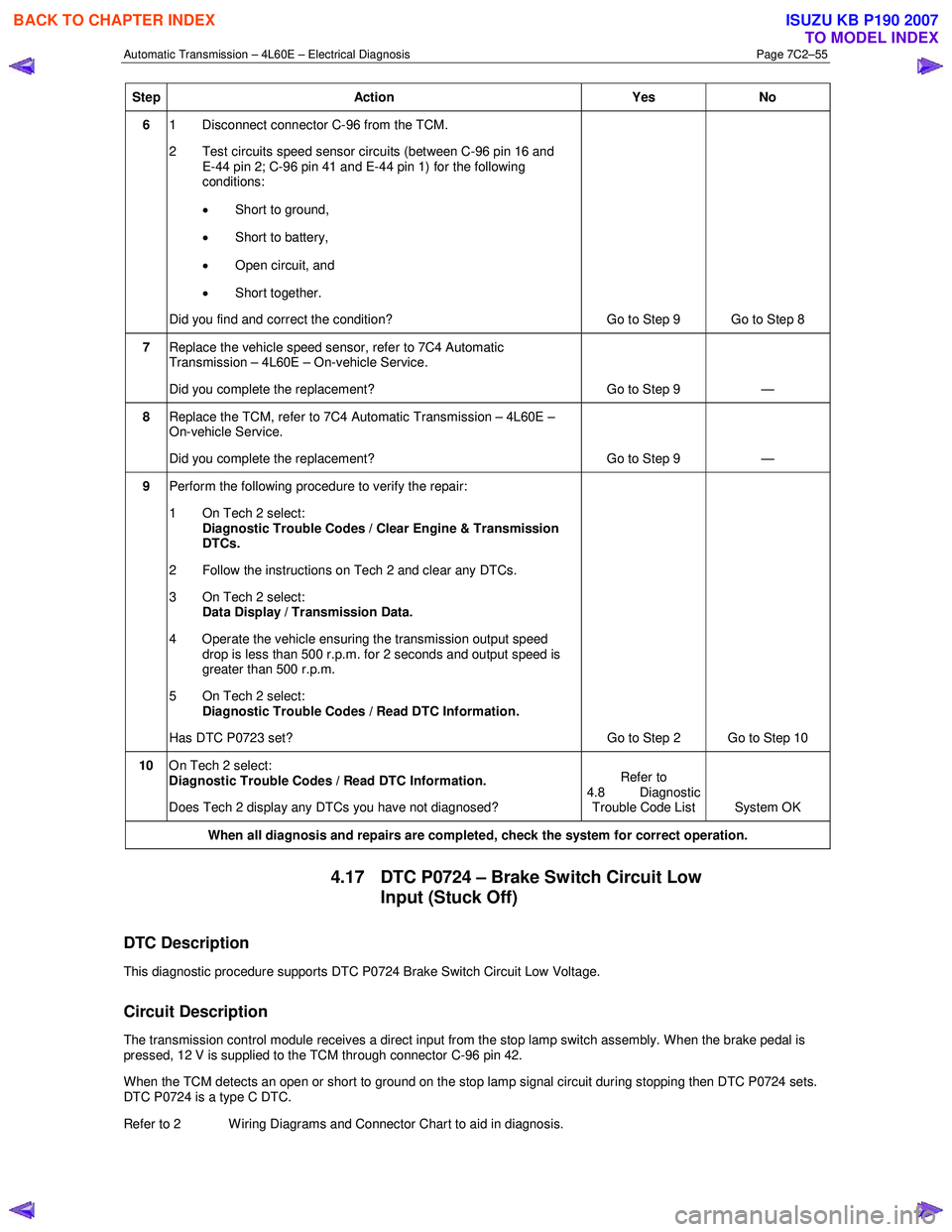
6 1 Disconnect connector C-96 from the TCM.
2 Test circuits speed sensor circuits (between C-96 pin 16 and E-44 pin 2; C-96 pin 41 and E-44 pin 1) for the following
conditions:
• Short to ground,
• Short to battery,
• Open circuit, and
• Short together.
Did you find and correct the condition? Go to Step 9 Go to Step 8
7 Replace the vehicle speed sensor, refer to 7C4 Automatic
Transmission – 4L60E – On-vehicle Service.
Did you complete the replacement? Go to Step 9 —
8 Replace the TCM, refer to 7C4 Automatic Transmission – 4L60E –
On-vehicle Service.
Did you complete the replacement? Go to Step 9 —
9 Perform the following procedure to verify the repair:
1 On Tech 2 select: Diagnostic Trouble Codes / Clear Engine & Transmission
DTCs.
2 Follow the instructions on Tech 2 and clear any DTCs.
3 On Tech 2 select: Data Display / Transmission Data.
4 Operate the vehicle ensuring the transmission output speed drop is less than 500 r.p.m. for 2 seconds and output speed is
greater than 500 r.p.m.
5 On Tech 2 select:
Diagnostic Trouble Codes / Read DTC Information.
Has DTC P0723 set? Go to Step 2 Go to Step 10
10 On Tech 2 select:
Diagnostic Trouble Codes / Read DTC Information.
Does Tech 2 display any DTCs you have not diagnosed? Refer to
4.8 Diagnostic Trouble Code List System OK
When all diagnosis and repairs are completed, check the system for correct operation.
4.17 DTC P0724 – Brake Switch Circuit Low
Input (Stuck Off)
DTC Description
This diagnostic procedure supports DTC P0724 Brake Switch Circuit Low Voltage.
Circuit Description
The transmission control module receives a direct input from the stop lamp switch assembly. When the brake pedal is
pressed, 12 V is supplied to the TCM through connector C-96 pin 42.
When the TCM detects an open or short to ground on the stop lamp signal circuit during stopping then DTC P0724 sets.
DTC P0724 is a type C DTC.
Refer to 2 W iring Diagrams and Connector Chart to aid in diagnosis.
BACK TO CHAPTER INDEX
TO MODEL INDEX
ISUZU KB P190 2007
Page 3842 of 6020
Automatic Transmission – 4L60E – Electrical Diagnosis Page 7C2–56
Conditions for Running the DTC
• No DTCs P0719, P0722 or P0723.
• The vehicle speed is greater than 40 km/h for 7 seconds, then 8 – 40 km/h for 5 seconds, then less than 8 km/h.
• Continuously eight times once the previous criteria have been met.
Conditions for Setting the DTC
The TCM detects an open or short to ground on the stop lamp switch signal circuit when the circuit should be high,
battery voltage.
Action Taken When the DTC Sets
• The TCM does not request the engine control module (ECM) to illuminate the MIL.
• The TCM records the operating conditions when the conditions for setting the DTC are met. The TCM records this
information as a Failure Record.
• The TCM stores DTC P0724 in TCM history.
Conditions for Clearing the DTC
•
The TCM clears the DTC from TCM history if the vehicle completes 40 warm-up cycles without a non-emission
related diagnostic fault occurring.
• Tech 2 can clear the DTC.
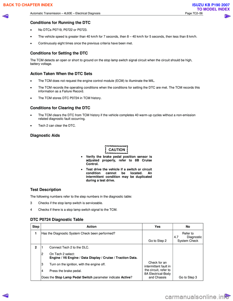
Diagnostic Aids
• Verify the brake pedal position sensor is
adjusted properly, refer to 8B Cruise
Control.
• Test drive the vehicle if a switch or circuit
condition cannot be located. An
intermittent condition may be duplicated
during a test drive.
Test Description
The following numbers refer to the step numbers in the diagnostic table:
3 Checks if the stop lamp switch is serviceable.
4 Checks if there is a stop lamp switch signal to the TCM.
DTC P0724 Diagnostic Table
Step Action Yes No
1 Has the Diagnostic System Check been performed?
Go to Step 2 Refer to
4.7 Diagnostic System Check
2 1 Connect Tech 2 to the DLC.
2 On Tech 2 select: Engine / V6 Engine / Data Display / Cruise / Traction Data.
3 Turn on the ignition, with the engine off.
4 Press the brake pedal.
Does the Stop Lamp Pedal Switch parameter indicate
Active? Check for an
intermittent fault in the circuit, refer to
8A Electrical-Body and Chassis Go to Step 3
BACK TO CHAPTER INDEX
TO MODEL INDEX
ISUZU KB P190 2007