2007 ISUZU KB P190 brake
[x] Cancel search: brakePage 4097 of 6020
7A3-12 ON-VEHICLE SERVICE (AW30–40LE)
Measure Line Pressure
1. Fully apply the parking brake and chock the four
wheels.
2. Start the engine and check idling rpm.
3. Select into “D" position, step down strongly on the brake pedal with your left foot and while
manipulating the accelerator pedal with the right
foot, measure the line pressures at the engine
speeds specified in the table.
4. In the same manner, perform the test in “R" position.
Line pressure kPa (kg/cm
2/psi) Engine
speed “D" position “R" position
Idling 349 – 408
(3.6 – 4.2 /51 – 59) 577 – 675
(5.9 – 6.9/84 – 98)
Stall 1,206 – 1,353
(12.3–13.8/175–196) 1,646 – 1,979
(16.8–20.2/239–287)
Evaluation
1. If the measured values at all positions are higher
than specified:
• Pressure control solenoid defective
• Primary regulator valve defective
2. If the measured values at all positions are lowe
r
than specified:
• Primary regulator valve defective
• Oil pump defective
• Pressure control solenoid defective
3. If pressure is low in “D" position only:
• “D" position circuit fluid leakage
4. If pressure is low in “R" position only:
• “R" position circuit fluid leakage
Road Test
NOTE: Perform the test at normal operating fluid
temperature (50 – 80 °C or 122 – 176 °F).
“D" Position Test in “NORMAL", and
“POWER" Pattern
Select into the “D" position and hold the accelerator
pedal constant at the 50% and 100% throttle valve
opening positions.
Push in one of the pattern selector buttons and check
the following:
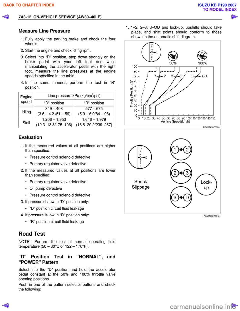
1. 1–2, 2–3, 3–OD and lock-up, upshifts should take
place, and shift points should conform to those
shown in the automatic shift diagram.
RTW 77ASH003001
RUA37ASH000101
BACK TO CHAPTER INDEX
TO MODEL INDEX
ISUZU KB P190 2007
Page 4099 of 6020
7A3-14 ON-VEHICLE SERVICE (AW30–40LE)
Evaluation
i. If there is no engine braking effect in the “2"
position:
• Second coast (No.1) brake is defective.
ii. If there is no engine braking effect in the “L" position:
• First and reverse (No.3) brake is defective.
RUW 37ASH000301
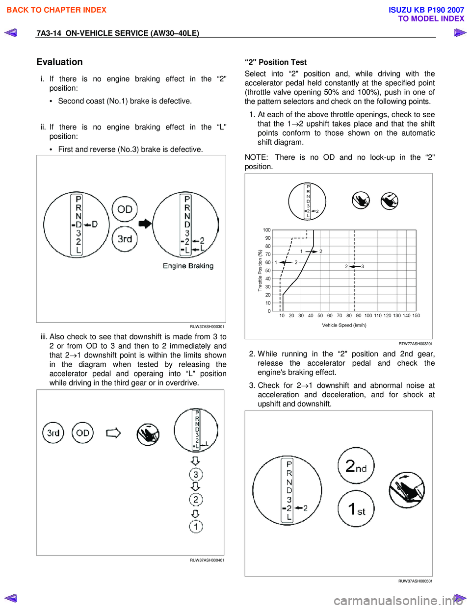
iii. Also check to see that downshift is made from 3 to
2 or from OD to 3 and then to 2 immediately and
that 2 →1 downshift point is within the limits shown
in the diagram when tested by releasing the
accelerator pedal and operaing into “L" position
while driving in the third gear or in overdrive.
RUW 37ASH000401
“2" Position Test
Select into “2" position and, while driving with the
accelerator pedal held constantly at the specified point
(throttle valve opening 50% and 100%), push in one o
f
the pattern selectors and check on the following points.
1.
At each of the above throttle openings, check to see
that the 1 →2 upshift takes place and that the shift
points conform to those shown on the automatic
shift diagram.
NOTE: There is no OD and no lock-up in the “2"
position.
RTW 77ASH003201
2. W hile running in the “2" position and 2nd gear,
release the accelerator pedal and check the
engine's braking effect.
3. Check for 2 →1 downshift and abnormal noise at
acceleration and deceleration, and for shock at
upshift and downshift.
RUW 37ASH000501
BACK TO CHAPTER INDEX
TO MODEL INDEX
ISUZU KB P190 2007
Page 4100 of 6020
ON-VEHICLE SERVICE (AW30–40LE) 7A3-15
“L" Position Test
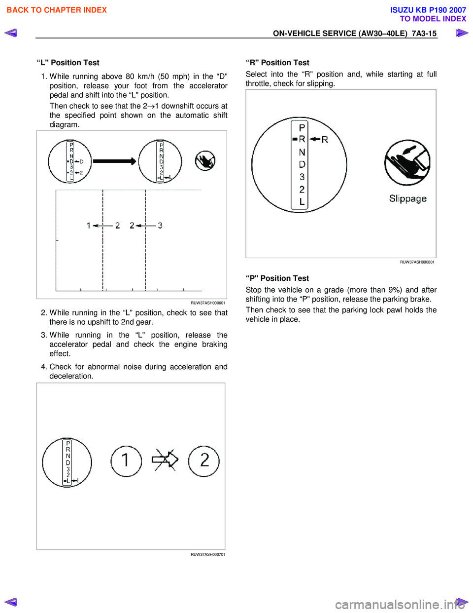
1. W hile running above 80 km/h (50 mph) in the “D"
position, release your foot from the accelerato
r
pedal and shift into the “L" position.
Then check to see that the 2 →1 downshift occurs at
the specified point shown on the automatic shift
diagram.
RUW 37ASH000601
2. W hile running in the “L" position, check to see that
there is no upshift to 2nd gear.
3. W hile running in the “L" position, release the accelerator pedal and check the engine braking
effect.
4. Check for abnormal noise during acceleration and deceleration.
RUW 37ASH000701
“R" Position Test
Select into the “R" position and, while starting at full
throttle, check for slipping.
RUW 37ASH000801
“P" Position Test
Stop the vehicle on a grade (more than 9%) and afte
r
shifting into the “P" position, release the parking brake.
Then check to see that the parking lock pawl holds the
vehicle in place.
BACK TO CHAPTER INDEX
TO MODEL INDEX
ISUZU KB P190 2007
Page 4103 of 6020
7A3-18 ON-VEHICLE SERVICE (AW30–40LE)
Transmission Fluid Level and Condition
Inspection
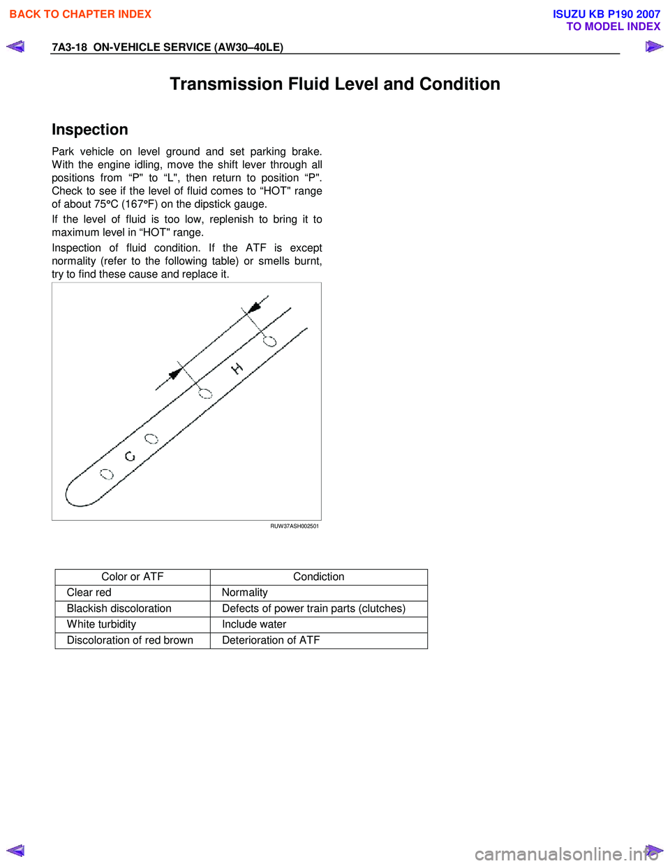
Park vehicle on level ground and set parking brake.
W ith the engine idling, move the shift lever through all
positions from “P" to “L", then return to position “P".
Check to see if the level of fluid comes to “HOT" range
of about 75 °
°°
°
C (167 °
°°
°
F) on the dipstick gauge.
If the level of fluid is too low, replenish to bring it to
maximum level in “HOT" range.
Inspection of fluid condition. If the ATF is except
normality (refer to the following table) or smells burnt,
try to find these cause and replace it.
RUW 37ASH002501
Color or ATF Condiction
Clear red Normality
Blackish discoloration Defects of power train parts (clutches)
W hite turbidity Include water
Discoloration of red brown Deterioration of ATF
BACK TO CHAPTER INDEX
TO MODEL INDEX
ISUZU KB P190 2007
Page 4106 of 6020
ON-VEHICLE SERVICE (AW30–40LE) 7A3-21
Brake Signal
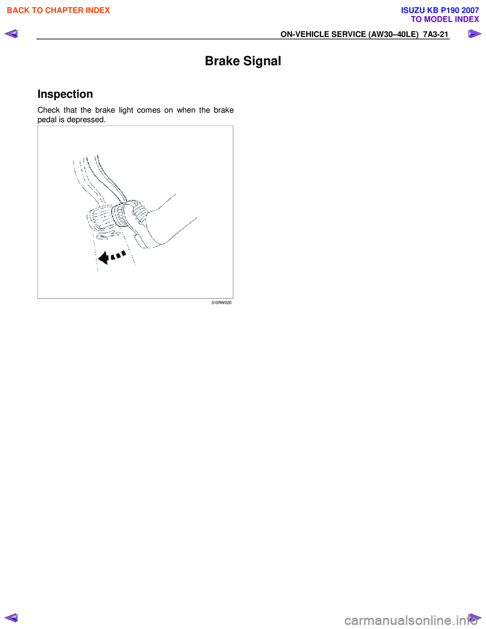
Inspection
Check that the brake light comes on when the brake
pedal is depressed.
310RW 020
BACK TO CHAPTER INDEX
TO MODEL INDEX
ISUZU KB P190 2007
Page 4134 of 6020
ON-VEHICLE SERVICE (AW30–40LE) 7A3-49
Major Components
Disassembly, inspection and reassembly of each
component group is indicated in the following chapter.
Before reassembly, make sure, again, that all
component groups are assembled correctly.
If something wrong is found in a certain component
group during assembly, inspect and repair this group
immediately.
General Assembly Notes:
1. The automatic transmission is composed of highly
precision-finished parts, necessitating careful
inspection before assembly because even a small
nick could cause fluid leakage or affect
performance.
2. Before assembling new clutch discs and brake
bands, soak them in automatic transmission fluid fo
r
at least thirty minutes.
3. Apply automatic transmission fluid on the sliding o
r
rotating surfaces of parts before assembly.
4. Use petroleum jelly to keep small parts in thei
r
palces.
5. Do not use adhesive cements on gaskets and similar parts.
6. W hen assembling the transmission, be sure to use new gaskets and O-rings.
7. Dry all parts with compressed air - never use shop rags.
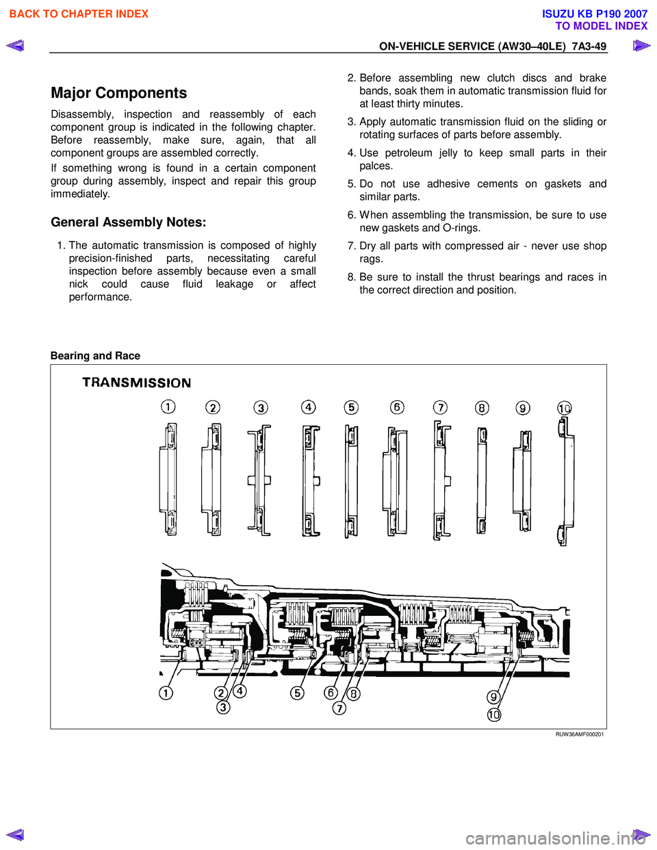
8. Be sure to install the thrust bearings and races in the correct direction and position.
Bearing and Race
RUW 36AMF000201
BACK TO CHAPTER INDEX
TO MODEL INDEX
ISUZU KB P190 2007
Page 4136 of 6020
UNIT REPAIR (AW30–40LE) 7A4–1
SECTION 7A4
TABLE OF CONTENTS
UNIT REPAIR (AW30–40LE)
Major Components (1) ................................... 7A4–2Major Components (1) and Associatedparts ........................................................... 7A4–2
Disassembly steps ...................................... 7A4–2
Components (1) ............................................. 7A4–4 Reassembly ................................................ 7A4–4
Major Components (2) ................................... 7A4–6 Major Componets (2) and Associated Parts ........................................................... 7A4–6
Disassembly ............................................... 7A4–7
Reassembly ................................................ 7A4–10
Major Components (3) ................................... 7A4–15 Major Components (3) and AssociatedParts ........................................................... 7A4–15
Disassembly ............................................... 7A4–16
Reassembly ................................................ 7A4–24
Diaassembly, Inspection and Reassembly of minor Components ................................. 7A4–36
Oil Pump ........................................................ 7A4–37 Disassembly View ...................................... 7A4–37
Disassembly ............................................... 7A4–37
Inspection and Repair ................................. 7A4–38
Reassembly ................................................ 7A4–40
OD Planetary Gear and OD Direct Clutch Assembly (C–0).......................................... 7A4–42
Disassembled View .................................... 7A4–42
Disassembly ............................................... 7A4–43
Inspection and Repair ................................. 7A4–46
Reassembly ................................................ 7A4–47
OD Support Assembly ................................... 7A4–52 Disassembled View .................................... 7A4–52
Disassembly ............................................... 7A4–52
Inspection and Repair ................................. 7A4–53
Reassembly ................................................ 7A4–54
Direct Clutch Assembly (C-2) ........................ 7A4–57 Disassembled View .................................... 7A4–57
Disassembly ............................................... 7A4–58
Inspection and Repair ................................. 7A4–59
Reassembly ................................................ 7A4–60
Forward Clutch Asseembly (C-1)................... 7A4–63 Disassembled View .................................... 7A4–63
Disassembly ............................................... 7A4–64
Inspection and Repair ................................. 7A4–65 Reassembly ................................................ 7A4–66
Front Planetary Gear ..................................... 7A4–70 Disassembled View .................................... 7A4–70
Disassembly ............................................... 7A4–70
Inspection and Repair ................................. 7A4–70
Reassembly ................................................ 7A4–71
Planetary Sun Gear and No.1 One-Way Clutch ......................................................... 7A4–72
Disassembled View .................................... 7A4–72
Disassembly ............................................... 7A4–73
Inspection and Repair ................................. 7A4–73
Reassembly ................................................ 7A4–74
Second Brake Assembly (B–2) ...................... 7A4–76 Disassembled View .................................... 7A4–76
Disassembly ............................................... 7A4–76
Inspection and Repair ................................. 7A4–77
Reassembly ................................................ 7A4–77
Rear Planetary Gear Assembly and Output Shaft ........................................................... 7A4–80
Disassembled View .................................... 7A4–80
Disassembly ............................................... 7A4–81
Reassembly ................................................ 7A4–83
First and Reverse Brake (B–3) ...................... 7A4–86 Disassembled View .................................... 7A4–86
Disassembly ............................................... 7A4–87
Reassembly ................................................ 7A4–88
Transmission Case ........................................ 7A4–91 Disassembled View .................................... 7A4–91
Disassembly ............................................... 7A4–91
Reassembly ................................................ 7A4–92
Torque Converter........................................... 7A4–94 Inspection and Repair ................................. 7A4–94
Adapter Housing (4 × 4)................................. 7A4–95
Disassembled View .................................... 7A4–95
Disassembly ............................................... 7A4–95
Reassembly ................................................ 7A4–95
Extension Housing (4 × 2) ............................. 7A4–96
Disassembled View .................................... 7A4–96
Disassembly ............................................... 7A4–96
Reassembly ................................................ 7A4–97
Main Data and Specifications ........................ 7A4–98
Special Tools ................................................. 7A4–102
BACK TO CHAPTER INDEX
TO MODEL INDEX
ISUZU KB P190 2007
Page 4144 of 6020
UNIT REPAIR (AW30–40LE) 7A4–9
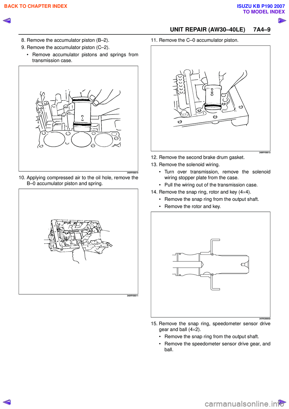
8. Remove the accumulator piston (B–2).
9. Remove the accumulator piston (C –2).
Remove accumulator pistons and springs from
transmission case.
240RY00010
10. Applying compressed air to the oil hole, remove the B–0 accumulator piston and spring.
240RY00011
11. Remove the C –0 accumulator piston.
240RY00012
12. Remove the second brake drum gasket.
13. Remove the solenoid wiring.
Turn over transmission, remove the solenoid
wiring stopper plate from the case.
Pull the wiring out of the transmission case.
14. Remove the snap ring, rotor and key (4 ×4).
Remove the snap ring from the output shaft.
Remove the rotor and key.
247R200002
15. Remove the snap ring, speedometer sensor drive
gear and ball (4 ×2).
Remove the snap ring from the output shaft.
Remove the speedometer sensor drive gear, and
ball.
BACK TO CHAPTER INDEX
TO MODEL INDEX
ISUZU KB P190 2007